2008 SUZUKI SWIFT Axle seal
[x] Cancel search: Axle sealPage 837 of 1496
Downloaded from www.Manualslib.com manuals search engine Manual Transmission/Transaxle: 5B-23
Transaxle Right Case Disassembly and
Assembly
S7RS0B5206016
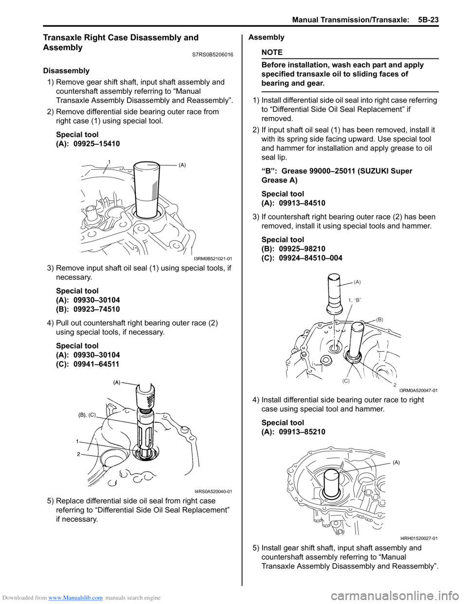
Disassembly1) Remove gear shift shaft, input shaft assembly and countershaft assembly referring to “Manual
Transaxle Assembly Disassembly and Reassembly”.
2) Remove differential side bearing outer race from right case (1) using special tool.
Special tool
(A): 09925–15410
3) Remove input shaft oil seal (1) using special tools, if necessary.
Special tool
(A): 09930–30104
(B): 09923–74510
4) Pull out countershaft right bearing outer race (2) using special tools, if necessary.
Special tool
(A): 09930–30104
(C): 09941–64511
5) Replace differential side oil seal from right case referring to “Differential Side Oil Seal Replacement”
if necessary. Assembly
NOTE
Before installation, wash each part and apply
specified transaxle oil to sliding faces of
bearing and gear.
1) Install differential side oil seal into right case referring
to “Differential Side O il Seal Replacement” if
removed.
2) If input shaft oil seal (1) has been removed, install it with its spring side facing upward. Use special tool
and hammer for installation and apply grease to oil
seal lip.
“B”: Grease 99000–25011 (SUZUKI Super
Grease A)
Special tool
(A): 09913–84510
3) If countershaft right bearing outer race (2) has been removed, install it using special tools and hammer.
Special tool
(B): 09925–98210
(C): 09924–84510–004
4) Install differential side bearing outer race to right case using special tool and hammer.
Special tool
(A): 09913–85210
5) Install gear shift shaft, input shaft assembly and countershaft assembly referring to “Manual
Transaxle Assembly Disassembly and Reassembly”.
(A)1
I3RM0B521021-01
I4RS0A520040-01
I3RM0A520047-01
(A)
I4RH01520027-01
Page 838 of 1496

Downloaded from www.Manualslib.com manuals search engine 5B-24 Manual Transmission/Transaxle:
Transaxle Left Case Disassembly and AssemblyS7RS0B5206017
Disassembly1) Replace differential side oil seal from left case referri ng to “Differential Side Oil Seal Replacement”, if necessary.
2) Remove input oil gutter (1) from left case, if necessary.
Assembly 1) If input oil gutter (1) has been removed, install it with bolt to which thread lock cement has been applied.
“A”: Thread lock cement 99000–32110 (Thread Lock Cement Super 1322)
Tightening torque
Oil gutter bolt (a): 10 N·m (1.0 kgf-m, 7.5 lb-ft)
2) If differential side oil seal is remov ed, install it to left case referring to “Differential Side Oil Seal Replacement”.
I4RH01520028-01
I3RM0A520048-01
Page 839 of 1496
Downloaded from www.Manualslib.com manuals search engine Manual Transmission/Transaxle: 5B-25
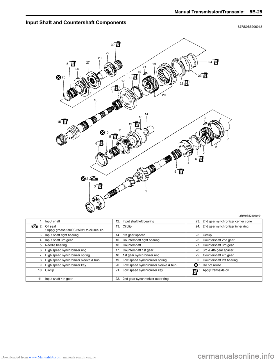
Input Shaft and Countershaft ComponentsS7RS0B5206018
I3RM0B521010-01
1. Input shaft12. Input shaft left bearing 23. 2nd gear synchronizer center cone
2. Oil seal : Apply grease 99000-25011 to oil seal lip. 13. Circlip
24. 2nd gear synchronizer inner ring
3. Input shaft right bearing 14. 5th gear spacer 25. Circlip
4. Input shaft 3rd gear 15. Countershaft right bearing 26. Countershaft 2nd gear
5. Needle bearing 16. Countershaft 27. Countershaft 3rd gear
6. High speed synchronizer ring 17. Countershaft 1st gear 28. 3rd & 4th gear spacer
7. High speed synchronizer spring 18. 1st gear synchronizer ring 29. Countershaft 4th gear
8. High speed synchronizer sleeve & hub 19. Low speed synchronizer spring 30. Countershaft left bearing
9. High speed synchronizer key 20. Low speed synchronizer sleeve & hub : Do not reuse.
10. Circlip 21. Low speed synchronizer key : Apply transaxle oil.
11. Input shaft 4th gear 22. 2nd gear synchronizer outer ring
Page 845 of 1496
Downloaded from www.Manualslib.com manuals search engine Manual Transmission/Transaxle: 5B-31
Synchronizer Parts InspectionS7RS0B5206021
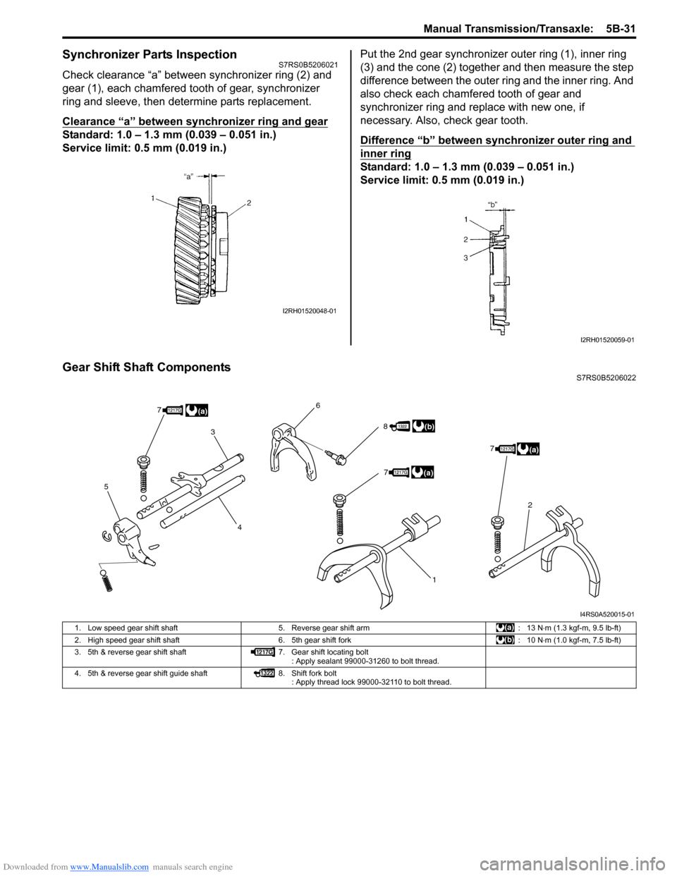
Check clearance “a” between synchronizer ring (2) and
gear (1), each chamfered tooth of gear, synchronizer
ring and sleeve, then determine parts replacement.
Clearance “a” between synchronizer ring and gear
Standard: 1.0 – 1.3 mm (0.039 – 0.051 in.)
Service limit: 0.5 mm (0.019 in.)Put the 2nd gear synchronizer outer ring (1), inner ring
(3) and the cone (2) together and then measure the step
difference between the outer ring and the inner ring. And
also check each chamfered tooth of gear and
synchronizer ring and replace with new one, if
necessary. Also, check gear tooth.
Difference “b” between synchronizer outer ring and
inner ring
Standard: 1.0 – 1.3 mm (0.039 – 0.051 in.)
Service limit: 0.5 mm (0.019 in.)
Gear Shift Shaft ComponentsS7RS0B5206022
I2RH01520048-01
I2RH01520059-01
5
3
4 6
1
2
8
7
77
(a)
(b)
(a)
(a)
I4RS0A520015-01
1. Low speed gear shift shaft
5. Reverse gear shift arm : 13 N⋅m (1.3 kgf-m, 9.5 lb-ft)
2. High speed gear shift shaft 6. 5th gear shift fork : 10 N⋅m (1.0 kgf-m, 7.5 lb-ft)
3. 5th & reverse gear shift shaft 7. Gear shift locating bolt
: Apply sealant 99000-31260 to bolt thread.
4. 5th & reverse gear shift guide shaft 8. Shift fork bolt
: Apply thread lock 99000-32110 to bolt thread.
Page 850 of 1496
Downloaded from www.Manualslib.com manuals search engine 5B-36 Manual Transmission/Transaxle:
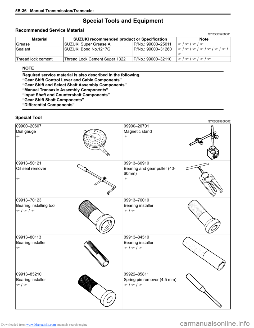
Special Tools and Equipment
Recommended Service MaterialS7RS0B5208001
NOTE
Required service material is also described in the following.
“Gear Shift Control Leve r and Cable Components”
“Gear Shift and Select Shaft Assembly Components”
“Manual Transaxle Assembly Components”
“Input Shaft and Countershaft Components”
“Gear Shift Shaft Components”
“Differential Components”
Special ToolS7RS0B5208002
Material SUZUKI recommended product or Specification Note
Grease SUZUKI Super Grease A P/No.: 99000–25011�) / �) / �) / �)
Sealant SUZUKI Bond No.1217G P/No.: 99000–31260�) / �) / �) / �) / �) / �) / �) /
�)
Thread lock cement Thread Lock Cement Super 1322 P/No.: 99000–32110 �) / �) / �) / �) / �)
09900–20607 09900–20701
Dial gauge Magnetic stand
�)�)
09913–50121 09913–60910
Oil seal remover Bearing and gear puller (40-
60mm)
�)�)
09913–70123 09913–76010
Bearing installing t ool Bearing installer
�) / �) / �)�) / �)
09913–80113 09913–84510
Bearing installer Bearing installer
�)�) / �) / �)
09913–85210 09922–85811
Bearing installer Spring pin remover (4.5 mm)
�) / �)�) / �) / �)
Page 851 of 1496

Downloaded from www.Manualslib.com manuals search engine Manual Transmission/Transaxle: 5B-37
09923–7451009923–78210
Bearing puller (20-35 mm) Bearing installer
�)�) / �) / �) / �)
09924–07710 09924–07730
Synchronizer hub installer Bearing installer
�)�)
09924–74510 09924–84510–004
Bearing and oil seal handle Bearing installer attachment
�)�)
09925–15410 09925–78210
Oil seal installer Spring pin remover (6 mm)
�)�)
09925–88210 09925–98210
Bearing puller attachment Input shaft bearing installer
�)�)
09926–27610 09927–76060
Oil seal installer Gear holder
�) / �)�) / �)
09930–30104 09940–51710
Sliding shaft Bearing installer
�) / �)�)
09941–64511 09951–16060
Bearing and oil seal remover
(30 mm Min.) Control arm bush remover
�)�)
Page 854 of 1496

Downloaded from www.Manualslib.com manuals search engine 5C-2 Clutch:
Diagnostic Information and Procedures
Clutch System Symptom DiagnosisS7RS0B5304001
Repair Instructions
Clutch Pedal InspectionS7RS0B5306001
Cylinder Push Rod Play “A”1) Press clutch pedal (1) gradually with finger, stop when slight increase of resistance is felt and
measure how much pedal has moved (push rod
play) as represented by “A” as shown.
Push rod play
“A”: Max. 3 mm (0.12 in.)
2) If “A” is not within specification, replace master cylinder (3) or pedal arm (2). Clutch Pedal Free Travel “B”
1) Depress clutch pedal (1), stop the moment clutch resistance is felt, and measure how much pedal has
moved (clutch pedal free travel) as represented by
“B” in figure.
Clutch pedal free travel
“B”
: 2 – 8 mm (0.08 – 0.31 in.)
2) If “B” is not within specification, check pedal arm (2) and master cylinder (3) and replace defective part.
Condition Possible cause Correction / Reference Item
Slipping Improper clutch pedal free travel Replace master cylinder or clutch pedal arm.
Worn or oily clutch disc facing Replace disc.
Warped disc, pressure plate or flywheel
surface Replace disc, clutch cover or flywheel.
Weakened diaphragm spring Replace clutch cover.
Master cylinder piston or seal cup not
returning Replace master cylinder.
Dragging clutch Improper clutch pedal free travel Replace master cylinder or clutch pedal arm.
Weakened diaphragm spring, or worn
spring tip Replace clutch cover.
Rusted input shaft splines Lubricate.
Damaged or worn splines of transaxle
input shaft Replace input shaft.
Excessively wobbly clutch disc Replace disc.
Clutch facings broken or dirty with oil Replace disc.
Fluid leakage Repair or replace.
Clutch vibration Glazed (glass-like) clutch facings Repair or replace disc.
Clutch facings dirty with oil Replace disc.
Release bearing slides unsmoothly on
input shaft bearing retainer Lubricate or replace input shaft bearing
retainer.
Wobbly clutch disc, or poor facing
contact Replace disc.
Weakened torsion springs in clutch disc Replace disc.
Clutch disc rivets loose Replace disc.
Distorted pressure plate or flywheel
surface Replace clutch cover or flywheel.
Weakened engine mounting Replace engine mounting.
Loosened engine mounting bolt or nut Retighten engine mounting bolt or nut.
Noisy clutch Worn or broken release bearing Replace release bearing.
Input shaft front bearing worn down Replace input shaft bearing.
Excessive rattle of clutch disc hub Replace disc.
Cracked clutch disc Replace disc.
Pressure plate and diaphragm spring
rattling Replace clutch cover.
Grabbing clutch Clutch disc facings soaked with oil Replace disc.
Clutch disc facings excessively worn Replace disc.
Rivet heads showing out of facing Replace disc.
Weakened torsion springs Replace disc.
Page 860 of 1496
Downloaded from www.Manualslib.com manuals search engine 5C-8 Clutch:
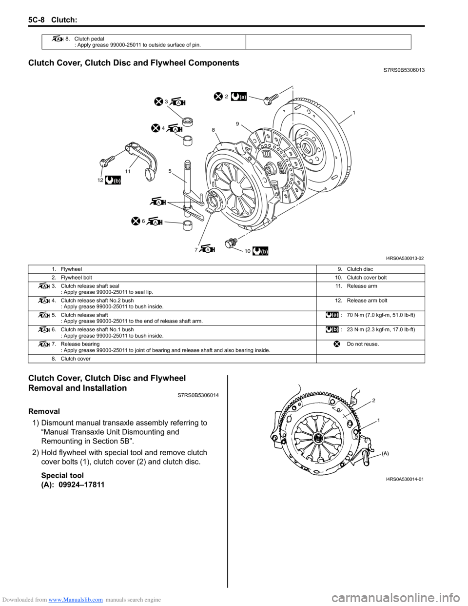
Clutch Cover, Clutch Disc and Flywheel ComponentsS7RS0B5306013
Clutch Cover, Clutch Disc and Flywheel
Removal and Installation
S7RS0B5306014
Removal1) Dismount manual transaxle assembly referring to “Manual Transaxle Unit Dismounting and
Remounting in Section 5B”.
2) Hold flywheel with specia l tool and remove clutch
cover bolts (1), clutch cover (2) and clutch disc.
Special tool
(A): 09924–17811
8. Clutch pedal : Apply grease 99000-25011 to outside surface of pin.
(a)
(b)
(b)
A
A
A
12
115
6
A3
A4
710
2
98
1
I4RS0A530013-02
1. Flywheel 9. Clutch disc
2. Flywheel bolt 10. Clutch cover bolt
3. Clutch release shaft seal : Apply grease 99000-25011 to seal lip. 11. Release arm
4. Clutch release shaft No.2 bush : Apply grease 99000-25011 to bush inside. 12. Release arm bolt
5. Clutch release shaft : Apply grease 99000-25011 to the end of release shaft arm. :70 N
⋅m (7.0 kgf-m, 51.0 lb-ft)
6. Clutch release shaft No.1 bush : Apply grease 99000-25011 to bush inside. :23 N
⋅m (2.3 kgf-m, 17.0 lb-ft)
7. Release bearing : Apply grease 99000-25011 to joint of bearing and release shaft and also bearing inside. Do not reuse.
8. Clutch cover
I4RS0A530014-01