2008 SUZUKI SWIFT lubri
[x] Cancel search: lubriPage 1157 of 1496
Downloaded from www.Manualslib.com manuals search engine Air Bag System: 8B-119
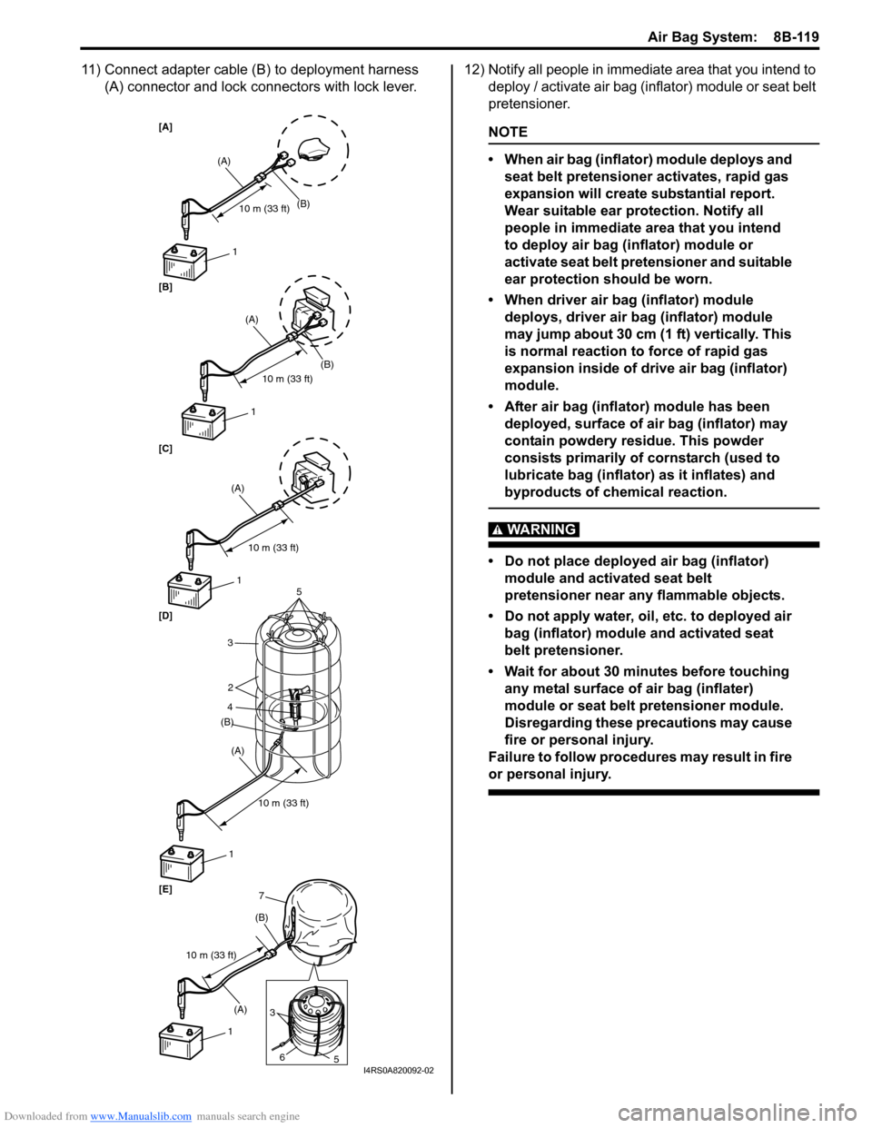
11) Connect adapter cable (B) to deployment harness (A) connector and lock connectors with lock lever. 12) Notify all people in immediate area that you intend to
deploy / activate air bag (inflator) module or seat belt
pretensioner.
NOTE
• When air bag (inflator) module deploys and seat belt pretensioner activates, rapid gas
expansion will create substantial report.
Wear suitable ear protection. Notify all
people in immediate area that you intend
to deploy air bag (inflator) module or
activate seat belt pretensioner and suitable
ear protection should be worn.
• When driver air bag (inflator) module deploys, driver air bag (inflator) module
may jump about 30 cm (1 ft) vertically. This
is normal reaction to force of rapid gas
expansion inside of drive air bag (inflator)
module.
• After air bag (inflator) module has been deployed, surface of air bag (inflator) may
contain powdery residue. This powder
consists primarily of cornstarch (used to
lubricate bag (inflator) as it inflates) and
byproducts of chemical reaction.
WARNING!
• Do not place deployed air bag (inflator) module and activated seat belt
pretensioner near any flammable objects.
• Do not apply water, oil, etc. to deployed air bag (inflator) module and activated seat
belt pretensioner.
• Wait for about 30 minutes before touching any metal surface of air bag (inflater)
module or seat belt pretensioner module.
Disregarding these precautions may cause
fire or personal injury.
Failure to follow procedures may result in fire
or personal injury.
[A]
10 m (33 ft)
(A)
(B)
1
10 m (33 ft)
(A)
(B) 1
5
3 2
4
(A)
[B]
[C]
[D]
[E]
7
3
6 5
(A) (B)
1
10 m (33 ft)
10 m (33 ft)
(A)
(B)
1
1
10 m (33 ft)
I4RS0A820092-02
Page 1161 of 1496
Downloaded from www.Manualslib.com manuals search engine Air Bag System: 8B-123
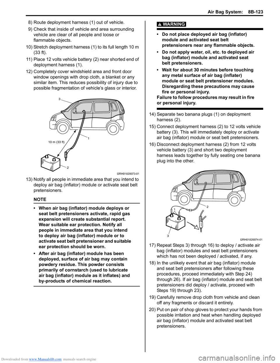
8) Route deployment harness (1) out of vehicle.
9) Check that inside of vehicle and area surrounding vehicle are clear of all people and loose or
flammable objects.
10) Stretch deployment harness (1) to its full length 10 m (33 ft).
11) Place 12 volts vehicle battery (2) near shorted end of deployment harness (1).
12) Completely cover windshield area and front door window openings with drop cloth, a blanket or any
similar item. This reduces possibility of injury due to
possible fragmentation of vehicle’s glass or interior.
13) Notify all people in immediate area that you intend to deploy air bag (inflator) module or activate seat belt
pretensioners.
NOTE
• When air bag (inflator) module deploys or seat belt pretensioners activate, rapid gas
expansion will create substantial report.
Wear suitable ear protection. Notify all
people in immediate area that you intend
to deploy air bag (inflator) module or to
activate seat belt pretensioner and suitable
ear protection should be worn.
• After air bag (inflator) module has been deployed, surface of air bag may contain
powdery residue. This powder consists
primarily of cornstarch (used to lubricate
air bag (inflator) module as it inflates) and
by-products of chemical reaction.
WARNING!
• Do not place deployed air bag (inflator) module and activated seat belt
pretensioners near any flammable objects.
• Do not apply water, oil, etc. to deployed air bag (inflator) module and activated seat
belt pretensioners.
• Wait for about 30 minutes before touching any metal surface of air bag (inflater)
module or seat belt pretensioner modules.
Disregarding these precautions may cause
fire or personal injury.
Failure to follow procedures may result in fire
or personal injury.
14) Separate two banana plugs (1) on deployment harness (2).
15) Connect deployment harness (2) to 12 volts vehicle battery (3). This will immedi ately deploy or activate
air bag (inflator) module or seat belt pretensioners.
16) Disconnect deployment harness (2) from 12 volts vehicle battery (3) and short two deployment
harness leads together by fully seating one banana
plug into the other.
17) Repeat Steps 3) through 16) to deploy / activate air bag (inflator) modules and seat belt pretensioners
which has not been deployed / activated, if any.
18) In the unlikely event that air bag (inflator) module and seat belt pretensioners after following these
procedures, proceed immediately with Step 24)
through 26). If air bag (inflator) module and seat belt
pretensioners did deploy / activate, proceed with
Steps 19) through 23).
19) Carefully remove drop cloth from vehicle and clean off any fragments or discard it entirely.
20) Put on pair of shop gloves to protect your hands from
possible irritation and heat when handling deployed
air bag (inflator) module and activated seat belt
pretensioners.
10 m (33 ft) 1
2
3
I2RH01820073-01
1
3 2
I2RH01820074-01
Page 1162 of 1496
Downloaded from www.Manualslib.com manuals search engine 8B-124 Air Bag System:
21) Disconnect adapter cable (special tool) from air bag (inflator) module or seat belt pretensioner as soon as
possible. This will preven t adapter cable (special
tool) from damage due to possible contact with hot
air bag (inflator) module or hot seat belt
pretensioner.
22) Check adapter cable connector as follows. Adapter cable connector (special tool) is designed to
be reused. However it should be inspected for
damage after deployment and replaced if necessary.
23) With air bag (inflator) modules deployed and seat belt pretensioners acti vated, vehicle may be
scrapped in the same manner as non-air bag system
/ seat belt pretensioner equipped vehicle.
NOTE
Remaining steps are to be followed in the
unlikely event that air bag (inflator) module
did not deploy or seat belt pretensioner did
not activate.
24) Remove undeployed air bag (inflator) module(s) and/ or inactivated seat belt pretensioner(s) from vehicle.
For driver air bag (inflator) module, refer to “Driver
Air Bag (Inflator) Module Removal and Installation”.
For passenger air bag (inflator) module, refer to
“Passenger Air Bag (Inflator) Module Removal and
Installation”. For seat belt pretensioner, refer to
“Front Seat Belt Removal an d Installation in Section
8A”.
25) Temporarily store undeployed air bag (inflator) module referring to “Precautions on Service and
Diagnosis of Air Bag System” for details.
26) Contact your local distribu tor for further assistance.
Deployed Air Bag (Inflator) Module and
Activated Seat Belt Pretensioner Disposal
S7RS0B8206019
WARNING!
Failure to follow proper air bag (inflator)
module and seat belt pretensioner disposal
procedures can result in air bag deployment
and pretensioner activation which may cause
personal injury. The undeployed air bag
(inflator) module and the inactivated seat belt
pretensioner must not be disposed of
through normal refuse channels.
The undeployed air bag (inflator) module and
the inactivated seat belt pretensioner
contains substances that can cause severe
illness or personal injury if the sealed
container is damaged during disposal.
Deployed air bag (inflator) module and the activated seat
belt pretensioner can be disposed of through normal
refuse channels just like any other parts. For their
disposal, however, the following points should be noted.
• The air bag (inflator) module and the seat belt
pretensioner immediately after deployment / activation
is very hot. Wait for 30 minu tes to cool it off before
handling it.
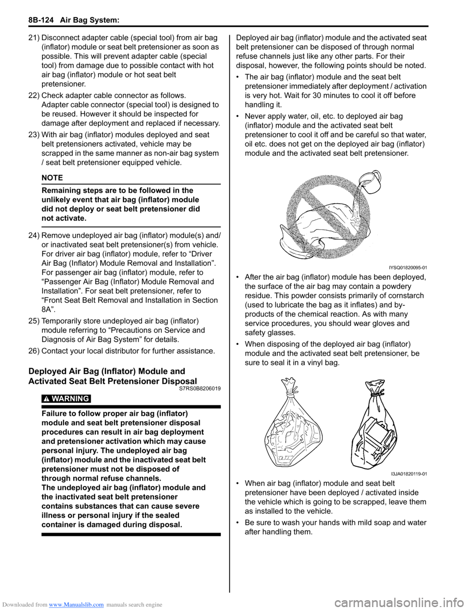
• Never apply water, oil, etc. to deployed air bag (inflator) module and the activated seat belt
pretensioner to cool it off and be careful so that water,
oil etc. does not get on the deployed air bag (inflator)
module and the activated seat belt pretensioner.
• After the air bag (inflator) module has been deployed, the surface of the air bag may contain a powdery
residue. This powder consists primarily of cornstarch
(used to lubricate the bag as it inflates) and by-
products of the chemical reaction. As with many
service procedures, you should wear gloves and
safety glasses.
• When disposing of the deployed air bag (inflator) module and the activated seat belt pretensioner, be
sure to seal it in a vinyl bag.
• When air bag (inflator) module and seat belt pretensioner have been deployed / activated inside
the vehicle which is going to be scrapped, leave them
as installed to the vehicle.
• Be sure to wash your hand s with mild soap and water
after handling them.
IYSQ01820095-01
I3JA01820119-01
Page 1337 of 1496
Downloaded from www.Manualslib.com manuals search engine Glass / Windows / Mirrors: 9E-10
Installation
Reverse removal procedure noting the following
instruction.
• Apply grease to sliding portions of window regulator.: Grease 99000–25011 (SUZUKI Super Grease A)
• Tighten front door window regulator attaching screws. Front door window regulator screw tightening
order
(a) → (b)
Front Door Window Regulator InspectionS7RS0B9506005
Check the following parts for wear, dama ge, smooth
operation and lubrication:
• Check regulator sliding and rotating parts.
• Check rollers.
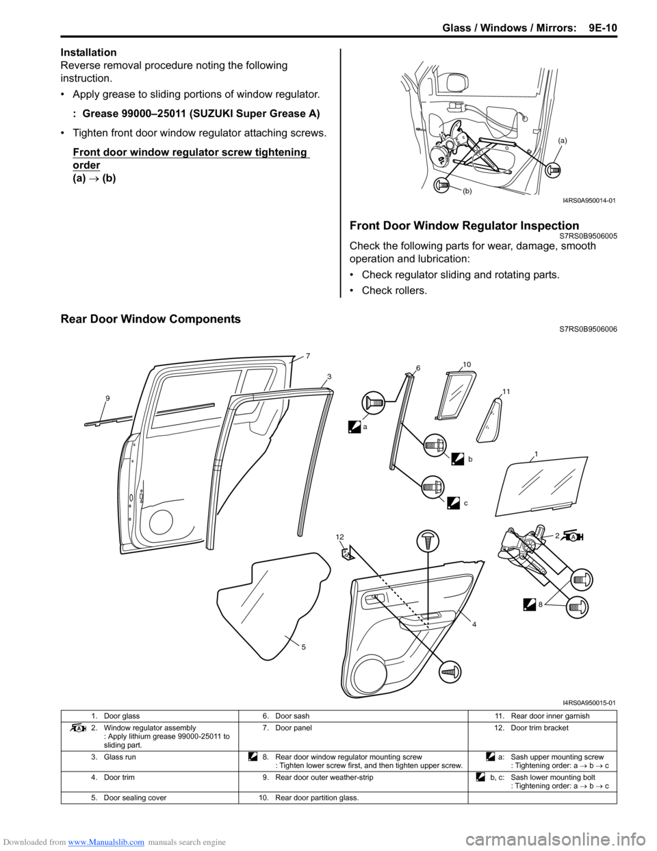
Rear Door Window ComponentsS7RS0B9506006
(a)
(b)
I4RS0A950014-01
9
7
3610
11
b
c
12
5 2
8
4
a
1
I4RS0A950015-01
1. Door glass
6. Door sash 11. Rear door inner garnish
2. Window regulator assembly : Apply lithium grease 99000-25011 to
sliding part. 7. Door panel
12. Door trim bracket
3. Glass run 8. Rear door window regulator mounting screw
: Tighten lower screw first, and then tighten upper screw. a: Sash upper mounting screw
: Tightening order: a → b → c
4. Door trim 9. Rear door outer weather-strip b, c: Sash lower mounting bolt
: Tightening order: a → b → c
5. Door sealing cover 10. Rear door partition glass.
Page 1370 of 1496
Downloaded from www.Manualslib.com manuals search engine 9J-1 Hood / Fenders / Doors:
Body, Cab and Accessories
Hood / Fenders / Doors
Repair Instructions
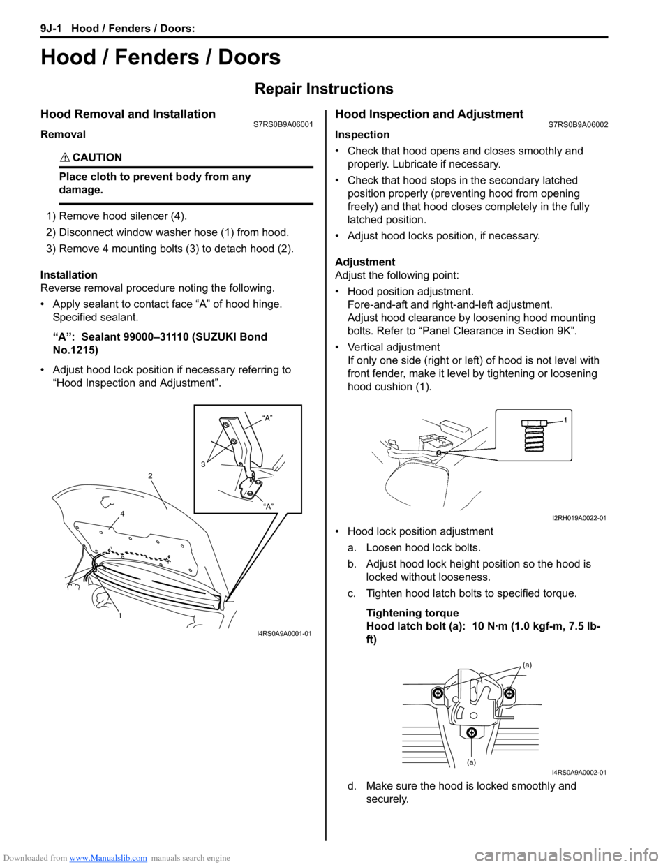
Hood Removal and InstallationS7RS0B9A06001
Removal
CAUTION!
Place cloth to prevent body from any
damage.
1) Remove hood silencer (4).
2) Disconnect window washer hose (1) from hood.
3) Remove 4 mounting bolts (3) to detach hood (2).
Installation
Reverse removal procedure noting the following.
• Apply sealant to contact face “A” of hood hinge. Specified sealant.
“A”: Sealant 99000–31110 (SUZUKI Bond
No.1215)
• Adjust hood lock position if necessary referring to “Hood Inspection and Adjustment”.
Hood Inspection and AdjustmentS7RS0B9A06002
Inspection
• Check that hood opens and closes smoothly and properly. Lubricate if necessary.
• Check that hood stops in the secondary latched position properly (preventing hood from opening
freely) and that hood closes completely in the fully
latched position.
• Adjust hood locks position, if necessary.
Adjustment
Adjust the following point:
• Hood position adjustment. Fore-and-aft and right-and-left adjustment.
Adjust hood clearance by loosening hood mounting
bolts. Refer to “Panel Clearance in Section 9K”.
• Vertical adjustment If only one side (right or left) of hood is not level with
front fender, make it level by tightening or loosening
hood cushion (1).
• Hood lock position adjustment a. Loosen hood lock bolts.
b. Adjust hood lock height position so the hood is locked without looseness.
c. Tighten hood latch bolts to specified torque.
Tightening torque
Hood latch bolt (a): 10 N·m (1.0 kgf-m, 7.5 lb-
ft)
d. Make sure the hood is locked smoothly and securely.
“A”
“A”
3
2
4
1
I4RS0A9A0001-01
I2RH019A0022-01
(a)
(a)I4RS0A9A0002-01