2008 SUZUKI SWIFT hand rem
[x] Cancel search: hand remPage 862 of 1496

Downloaded from www.Manualslib.com manuals search engine 5C-10 Clutch:
3) Aligning clutch disc to flywheel center using special
tool, install clutch cover (1) and bolts (2). Then
tighten bolts (2) to specification.
NOTE
• While tightening clutch cover bolts, compress clutch disc with special tool
(clutch center guide) by hand so that disc
is centered.
• Tighten cover bolts little by little evenly in diagonal order.
Special tool
(A): 09924–17811
(B): 09923–36320
Tightening torque
Clutch cover bolt (a): 23 N·m (2.3 kgf-m, 17.0 lb-
ft)
4) Slightly apply grease to input shaft (1), then join manual transaxle assembly with engine referring to
“Manual Transaxle Unit Dismounting and
Remounting in Section 5B”.
“A”: Grease 99000–25210 (SUZUKI Super
Grease I)
NOTE
When inserting transaxle input shaft to clutch
disc, turn crankshaft li ttle by little to match
the splines.
Clutch Cover, Clutch Disc and Flywheel
Inspection
S7RS0B5306015
Input Shaft Bearing
Check bearing (1) for smooth ro tation and replace it if
abnormality is found.
Clutch Disc
Measure depth of rivet head depression, i.e. distance
between rivet head and facing surface.
If depression is found to hav e reached service limit at
any of rivet holes (2), repl ace clutch disc assembly (1).
Rivet head depth
Standard: 1.65 – 2.25 mm (0.06 – 0.09 in.)
Limit: 0.5 mm (0.02 in.)
I4RS0A530017-01
I4RS0A530018-01
I3RM0A530014-01
I4RS0A530019-01
Page 872 of 1496
Downloaded from www.Manualslib.com manuals search engine 6B-1 Steering Wheel and Column:
Steeri ng
Steering Wheel and Column
Precautions
Service Precautions of Steering Wheel and
Column
S7RS0B6200001
For service precautions, refer to “Precautions on Service
and Diagnosis of Air Bag System in Section 8B”.
Service and Diagnosis
For diagnosis and servicing, refer to “Precautions on
Service and Diagnosis of Air Bag System in Section 8B”.
Disabling Air Bag System
For disabling air bag system, refer to “Disabling Air Bag
System in Section 8B”. Enabling Air Bag System
For enabling air bag system, refer to “Enabling Air Bag
System in Section 8B”.
Handling and Storage
For handling and storage, refer to “Precautions on
Handling and Storage of Air Bag System Components in
Section 8B”.
Disposal
For disposal, refer to “Prec
autions on Disposal of Air
Bag and Seat Belt Pretensioner in Section 8B”.
General Description
Steering Wheel and Column ConstructionS7RS0B6201001
This double tube type steering column has the following three important features in addition to the steering function:
• The column is energy absorbing, desig ned to compress in a front-end collision.
• The ignition switch and lock are mounted conveniently on this column.
• With the column mounted lock, the ignition and steering op erations can be locked to inhibit theft of the vehicle.
To insure the energy absorbing action, it is important th at only the specified screws, bolts and nuts be used as
designated, and that they are tightened to the specified torque. When the column assembly is removed from the
vehicle, special care must be taken in handling it. Use of a steering wheel puller or a sharp blow on the end of the
steering shaft, leaning on the assembly, or dropping the a ssembly could shear the plastic shear pins which maintain
column length and position.
The driver air bag (inflator) module is one of the supplemental restraint (air bag) system components and is mounted
to the center of the steering wheel. During certain frontal crashes, the air bag system supplements the restraint of the
driver’s and passenger’s seat belts by deploying the air b ags. The air bag (inflator) module should be handled with
care to prevent accidental deployment. When servicing, be sure to observe “Precautions on Service and Diagnosis of
Air Bag System in Section 8B”.
Page 949 of 1496
Downloaded from www.Manualslib.com manuals search engine Air Conditioning System: Manual Type 7B-1
HVAC
Air Conditioning System
Manual Type
Precautions
A/C System CautionS7RS0B7210001
CAUTION!
• The air conditioning system of this vehicle uses refrigerant HFC-134a (R-134a).
None of refrigerant, compressor oil and component parts is interchangeable between two types of
A/C: one using refrigerant HFC-134a (R-134a) and the other using refrigerant CFC-12 (R-12).
Be sure to check which refrigerant is used be fore any service work including inspection and
maintenance. For identification between these two types, refer to “Refrigerant Type Identification”.
When replenishing or changing refrigerant and comp ressor oil and when replacing parts, make sure
that the material or the part to be used is appropriate to the A/C installed in the vehicle being
serviced.
Use of incorrect one will result in leakage of refrigerant, damage in parts or other faulty condition.
• When servicing the compressor, keep dirt or foreign material away from getting on or into the compressor parts and system. Clean tools and a clean work area are important for proper service.
The compressor connection and the outside of the compressor should be cleaned before any “On
vehicle” repair or before removal of the compressor. The parts must be kept clean at all times and
any parts to be reassembled should be cleaned with trichloromethane, naphtha, kerosene or
equivalent solvent and dried with dry air. Use only lint free cloths to wipe parts.
• When compressor is removed from the vehicle for servicing, the oil remaining in the compressor
should be discarded and new refrigerant oil added to the compressor.
Minor repair procedures may be done on the vehicle without discharging the system. Major repair
procedures require that the system be discharged of refrigerant.
Precautions on Servicing A/C SystemS7RS0B7210002
WARNING!
Should refrigerant HFC-134a (R-134a) is exposed to your eye(s), consult a doctor immediately.
• Do not use your hand to rub affected eye(s). Instead, use fresh cold water to splash it over affected area to thus gradually raise its temperature above the freezing point.
• Obtain proper treatment as soon as possible from a doctor or eye specialist. Should liquid refrigerant HFC-134a (R-134a) is exposed to your skin, such affected part should be treated in the
same manner as when skin is frostbitten or frozen.
Handling Refrigerant HFC-134a (R-134a)
• Always wear goggles to protect your eyes.
• Avoid direct contact to liquid refrigerant.
• Do not heat refrigerant container higher than 40 °C (104 ° F).
• Do not discharge refrigerant into atmosphere.
• Do not expose bright metals to liquid refrigerant. Refrig erant combined with moisture is corrosive and tarnishes
surfaces of bright metals including chrome.
Page 965 of 1496
Downloaded from www.Manualslib.com manuals search engine Air Conditioning System: Manual Type 7B-17
NOTE
• After recovering refrigerant from system, the amount of removed compressor oil must be measured
for replenishing compressor oil.
• When handling recovery and recycling equipment, be sure to follow the instruction manual for the equipment.
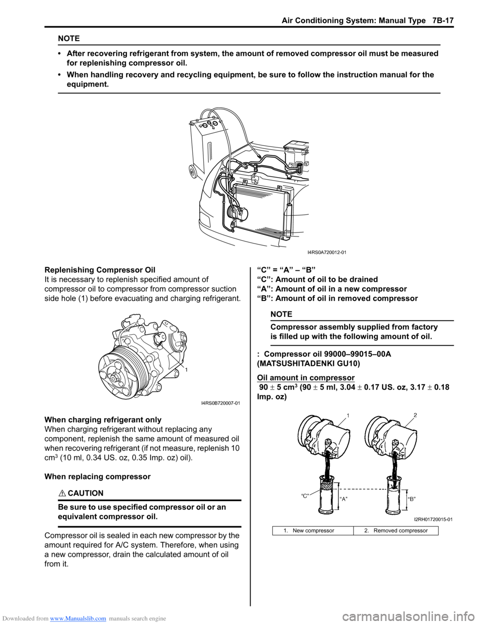
Replenishing Compressor Oil
It is necessary to replenish specified amount of
compressor oil to compressor from compressor suction
side hole (1) before evacuating and charging refrigerant.
When charging refrigerant only
When charging refrigerant without replacing any
component, replenish the same amount of measured oil
when recovering refrigerant (if not measure, replenish 10
cm
3 (10 ml, 0.34 US. oz, 0.35 Imp. oz) oil).
When replacing compressor
CAUTION!
Be sure to use specified compressor oil or an
equivalent compressor oil.
Compressor oil is sealed in each new compressor by the
amount required for A/C system. Therefore, when using
a new compressor, drain the calculated amount of oil
from it. “C” = “A” – “B”
“C”: Amount of oil to be drained
“A”: Amount of oil in a new compressor
“B”: Amount of oil in removed compressor
NOTE
Compressor assembly su
pplied from factory
is filled up with the following amount of oil.
: Compressor oil 99000–99015–00A
(MATSUSHITADENKI GU10)
Oil amount in compressor
90 ± 5 cm3 (90 ± 5 ml, 3.04 ± 0.17 US. oz, 3.17 ± 0.18
Imp. oz)
I4RS0A720012-01
1
I4RS0B720007-01
1. New compressor 2. Removed compressor
I2RH01720015-01
Page 968 of 1496
Downloaded from www.Manualslib.com manuals search engine 7B-20 Air Conditioning System: Manual Type
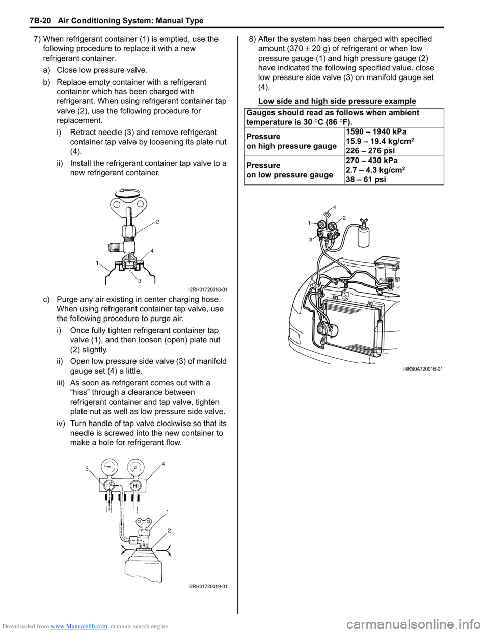
7) When refrigerant container (1) is emptied, use the following procedure to replace it with a new
refrigerant container.
a) Close low pressure valve.
b) Replace empty container with a refrigerant container which has been charged with
refrigerant. When using refrigerant container tap
valve (2), use the following procedure for
replacement.
i) Retract needle (3) and remove refrigerant container tap valve by loosening its plate nut
(4).
ii) Install the refrigerant container tap valve to a new refrigerant container.
c) Purge any air existing in center charging hose. When using refrigerant container tap valve, use
the following procedure to purge air.
i) Once fully tighten refrigerant container tap valve (1), and then loosen (open) plate nut
(2) slightly.
ii) Open low pressure side valve (3) of manifold
gauge set (4) a little.
iii) As soon as refrigerant comes out with a “hiss” through a clearance between
refrigerant container and tap valve, tighten
plate nut as well as low pressure side valve.
iv) Turn handle of tap valve clockwise so that its needle is screwed into the new container to
make a hole for refrigerant flow. 8) After the system has been charged with specified
amount (370 ± 20 g) of refrigerant or when low
pressure gauge (1) and high pressure gauge (2)
have indicated the following specified value, close
low pressure side valve (3) on manifold gauge set
(4).
Low side and high side pressure example
I2RH01720018-01
I2RH01720019-01
Gauges should read as follows when ambient
temperature is 30 °C (86 °F).
Pressure
on high pressure gauge 1590 – 1940 kPa
15.9 – 19.4 kg/cm
2
226 – 276 psi
Pressure
on low pressure gauge 270 – 430 kPa
2.7 – 4.3 kg/cm
2
38 – 61 psi
1
3 42
I4RS0A720016-01
Page 978 of 1496
Downloaded from www.Manualslib.com manuals search engine 7B-30 Air Conditioning System: Manual Type
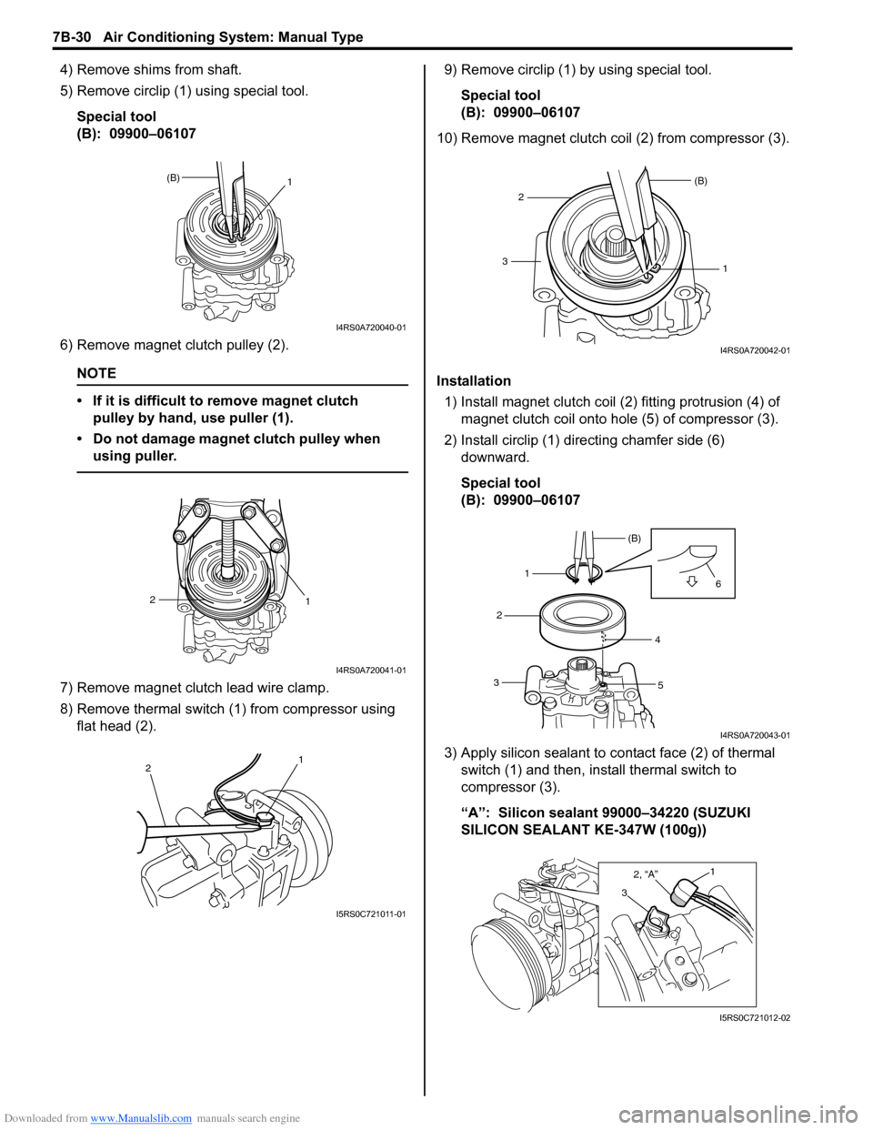
4) Remove shims from shaft.
5) Remove circlip (1) using special tool.Special tool
(B): 09900–06107
6) Remove magnet clutch pulley (2).
NOTE
• If it is difficult to remove magnet clutch pulley by hand, use puller (1).
• Do not damage magnet clutch pulley when using puller.
7) Remove magnet clutch lead wire clamp.
8) Remove thermal switch (1) from compressor using flat head (2). 9) Remove circlip (1) by using special tool.
Special tool
(B): 09900–06107
10) Remove magnet clutch coil (2) from compressor (3).
Installation 1) Install magnet clutch coil (2) fitting protrusion (4) of magnet clutch coil onto hole (5) of compressor (3).
2) Install circlip (1) dire cting chamfer side (6)
downward.
Special tool
(B): 09900–06107
3) Apply silicon sealant to co ntact face (2) of thermal
switch (1) and then, inst all thermal switch to
compressor (3).
“A”: Silicon sealant 99000–34220 (SUZUKI
SILICON SEALANT KE-347W (100g))
(B) 1
I4RS0A720040-01
1
2
I4RS0A720041-01
2 1
I5RS0C721011-01
1
(B)
23
I4RS0A720042-01
1 (B)
2
3 4
5 6
I4RS0A720043-01
3
2, “A”1
I5RS0C721012-02
Page 1029 of 1496
Downloaded from www.Manualslib.com manuals search engine Table of Contents 8- i
8
Section 8
CONTENTS
Restraint
Precautions ................................................. 8-1
Precautions............................................................. 8-1
Precautions on Restraint ....................................... 8-1
Seat Belts .......... ............................... ........ 8A-1
Precautions........................................................... 8A-1
Precautions on Service a nd Diagnosis of Seat
Belt .................................................................... 8A-1
General Description ............................................. 8A-1 Seat Belt Construction ........................................ 8A-1
Diagnostic Information and Procedures ............ 8A-2 Repair and Inspection Required after Accident ............................................................ 8A-2
Repair Instructions .............................................. 8A-3 Front Seat Belt Components ............................... 8A-3
Front Seat Belt Removal and Installation ............ 8A-4
Front Seat Belt Inspection ................................... 8A-4
Rear Seat Belt Components ............................... 8A-6
Rear Seat Belt Removal and Installation ............ 8A-7
Rear Seat Belt Inspection ................................... 8A-7
Specifications ....................................................... 8A-7
Tightening Torque Specifications ........................ 8A-7
Air Bag System ............... ......................... 8B-1
Precautions........................................................... 8B-1
Precautions on Service and Diagnosis of Air Bag System....................................................... 8B-1
Precautions on Handling and Storage of Air Bag System Components . ................................ 8B-2
Precautions on Disposal of Air Bag and Seat
Belt Pretensioner .............................................. 8B-5
General Description ............................................. 8B-5 Air Bag System Construction .............................. 8B-5
Air Bag System Input / Output Table .................. 8B-6
Schematic and Routing Diagram ........................ 8B-7 Air Bag System Wiring Circuit Diagram .............. 8B-7
Component Locatio n ........................................... 8B-9
Air Bag System Components, Wiring and Connectors Location ......................................... 8B-9
Diagnostic Information and Procedures .......... 8B-10 Air Bag Diagnostic System Check .................... 8B-10
Air Bag Diagnostic System Check Flow ............ 8B-10
DTC Table ......................................................... 8B-11
DTC Check ....................................................... 8B-12 DTC Clearance ................................................. 8B-12
Scan Tool Data ................................................. 8B-13
“AIR BAG” Warning Right Comes ON Steady .. 8B-13
“AIR BAG” Warning Right Does Not Come
ON ................................................................... 8B-15
“AIR BAG” Warning Right Flashes .................... 8B-16
DTC B1013: SDM fault...................................... 8B-17
DTC B1014: “AIR BAG” Warning Right Circuit Failure ............................................................. 8B-17
DTC B1016: Power Source Voltage High ......... 8B-18
DTC B1017: Power Source Voltage Low .......... 8B-20
DTC B1021: Front Air Bag Module Deployed ... 8B-22
DTC B1024 / B1025: Side-Air Bag (Driver / Passenger) Deployed...................................... 8B-22
DTC B1026: Pretensioner Activated ................. 8B-23
DTC B1027: Reusable Number Exceeded ....... 8B-24
DTC B1031: Driver Air Bag Initiator Circuit
Resistance High .............................................. 8B-24
DTC B1032: Driver Air Bag Initiator Circuit
Resistance Low ............................................... 8B-29
DTC B1033: Driver Air Bag Initiator Circuit
Short to Ground............................................... 8B-34
DTC B1034: Driver Air Bag Initiator Circuit
Short to Power Circuit .... ................................. 8B-39
DTC B1041: Passenger Air Bag Initiator Circuit Resistance High ................................... 8B-44
DTC B1042: Passenger Air Bag Initiator Circuit Resistance Low.................................... 8B-47
DTC B1043: Passenger Air Bag Initiator Circuit Short to Ground ................................... 8B-50
DTC B1044: Passenger Air Bag Initiator Circuit Short to Power Circ uit .......................... 8B-53
DTC B1051 / B1055: Driver / Passenger Pretensioner Initiator Circuit Resistance
High ................................................................. 8B-56
DTC B1052 / B1056: Driver / Passenger Pretensioner Initiator Circu it Resistance Low .. 8B-58
DTC B1053 / B1057: Driver / Passenger Pretensioner Initiator Circuit Short to Ground .. 8B-60
DTC B1054 / B1058: Driver / Passenger Pretensioner Initiator Circuit Short to Power
Circuit .............................................................. 8B-62
DTC B1061 / B1065: Driver / Passenger Side- Air Bag Initiator Circuit Resistance High ......... 8B-64
Page 1039 of 1496
Downloaded from www.Manualslib.com manuals search engine Air Bag System: 8B-1
Restraint
Air Bag System
Precautions
Precautions on Service and Diagnosis of Air
Bag System
S7RS0B8200001
WARNING!
• If the air bag system and another vehicle system both need repair, SUZUKI
recommends that the air bag system be
repaired first, to help avoid unintended air
bag system activation.
• Do not modify the steering wheel, dashboard, both front seat or any other on
or around air bag system components.
Modifications can adversely affect air bag
system performance and lead to injury.
• Be sure to follow the procedures described in this section. Failure to follow
procedures could result in possible air bag
system activation, personal injury or
unneeded air bag system repairs.
• WARNING / CAUTION labels are attached on each
part of air bag system components (SDM, air bag
(inflator) modules and seat belt pretensioners). Be
sure to follow the instructions.
• Many of service procedures require disconnection of
“A/BAG” fuse and air bag (inflator) module(s) (driver,
passenger, side of both si des and curtain of both
sides) from initiator circuit to avoid an accidental
deployment.
• Do not apply power to the air bag system unless all components are connected or a diagnostic flow
requests it, as this will set a DTC.
• The “Air Bag Diagnostic S ystem Check” must be the
starting point of any air bag diagnostics. The “Air Bag
Diagnostic System Check” will verify proper “AIR
BAG” warning right operatio n and will lead you to the
correct flow to diagnose any air bag malfunctions.
Bypassing these procedures may result in extended
diagnostic time, incorrect diagnosis, and incorrect
parts replacements. • Never use air bag component parts from another
vehicle.
• If the vehicle will be exposed to temperatures over 93
° C (200 °F) (for example, during a paint baking
process), remove the air bag system components
beforehand to avoid component damage or
unintended system activation.
• When handling the air bag (inflator) modules (driver, passenger, side of both si des and curtain of both
sides), seat belt pretensio ners (driver and passenger),
SDM, forward-sensor or side-sensor, be careful not to
drop it or apply an impact to it. If an excessive impact
was applied (e.g., SDM, forward-sensor and side-
sensor are dropped, air bag (inflator) module is
dropped from a height of 90 cm (3 ft) or more, seat
belt pretensioner (retractor assembly) is dropped from
a height of 30 cm (1 ft) or more), never attempt
disassembly or repair but replace it with a new one.
• When using electric welding, be sure to disconnect air bag (inflator) module connectors (driver, passenger,
side of both sides and curtain of both sides) and seat
belt pretensioner connectors (driver and passenger)
respectively.
• When applying paint around the air bag system related parts, use care so that the harness or
connector will not be expo sed to the paint mist.
• Never expose air bag system component parts directly to hot air (drying or baking the vehicle after
painting) or flames.
WARNING!
When performing service on or around air
bag system components or air bag wiring,
follow the procedures listed in “Disabling Air
Bag System” to temporarily disable the air
bag system.
Failure to follow procedures could result in
possible air bag system activation, personal
injury or unneeded air bag system repairs.