2008 SUZUKI SWIFT clutch
[x] Cancel search: clutchPage 685 of 1496

Downloaded from www.Manualslib.com manuals search engine Automatic Transmission/Transaxle: 5A-41
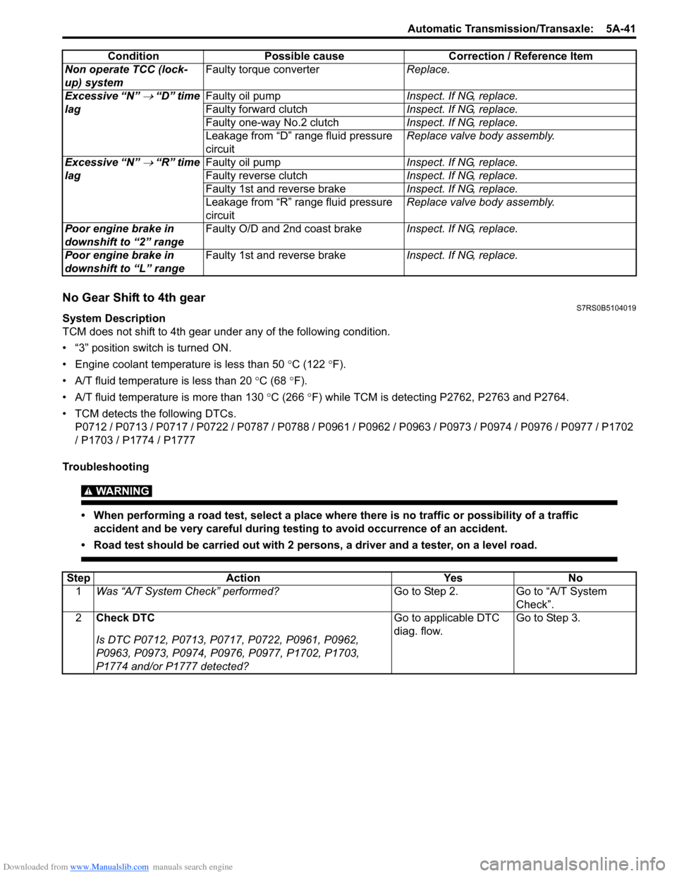
No Gear Shift to 4th gearS7RS0B5104019
System Description
TCM does not shift to 4th gear under any of the following condition.
• “3” position switch is turned ON.
• Engine coolant temperature is less than 50 °C (122 °F).
• A/T fluid temperature is less than 20 °C (68 °F).
• A/T fluid temperature is more than 130 °C (266 °F) while TCM is detecting P2762, P2763 and P2764.
• TCM detects the following DTCs. P0712 / P0713 / P0717 / P0722 / P0787 / P0788 / P0961 / P0962 / P0963 / P0973 / P0974 / P0976 / P0977 / P1702
/ P1703 / P1774 / P1777
Troubleshooting
WARNING!
• When performing a road test, select a place where there is no traffic or possibility of a traffic accident and be very careful during testing to avoid occurrence of an accident.
• Road test should be carried out with 2 persons, a driver and a tester, on a level road.
Non operate TCC (lock-
up) system Faulty torque converter
Replace.
Excessive “N”
→ “D” time
lag Faulty oil pump
Inspect. If NG, replace.
Faulty forward clutch Inspect. If NG, replace.
Faulty one-way No.2 clutch Inspect. If NG, replace.
Leakage from “D” range fluid pressure
circuit Replace valve body assembly.
Excessive “N”
→ “R” time
lag Faulty oil pump
Inspect. If NG, replace.
Faulty reverse clutch Inspect. If NG, replace.
Faulty 1st and reverse brake Inspect. If NG, replace.
Leakage from “R” range fluid pressure
circuit Replace valve body assembly.
Poor engine brake in
downshift to “2” range Faulty O/D and 2nd coast brake
Inspect. If NG, replace.
Poor engine brake in
downshift to “L” range Faulty 1st and reverse brake
Inspect. If NG, replace.
Condition Possible cause Correction / Reference Item
Step
Action YesNo
1 Was “A/T System Check” performed? Go to Step 2.Go to “A/T System
Check”.
2 Check DTC
Is DTC P0712, P0713, P0717, P0722, P0961, P0962,
P0963, P0973, P0974, P0976, P0977, P1702, P1703,
P1774 and/or P1777 detected? Go to applicable DTC
diag. flow.
Go to Step 3.
Page 695 of 1496

Downloaded from www.Manualslib.com manuals search engine Automatic Transmission/Transaxle: 5A-51
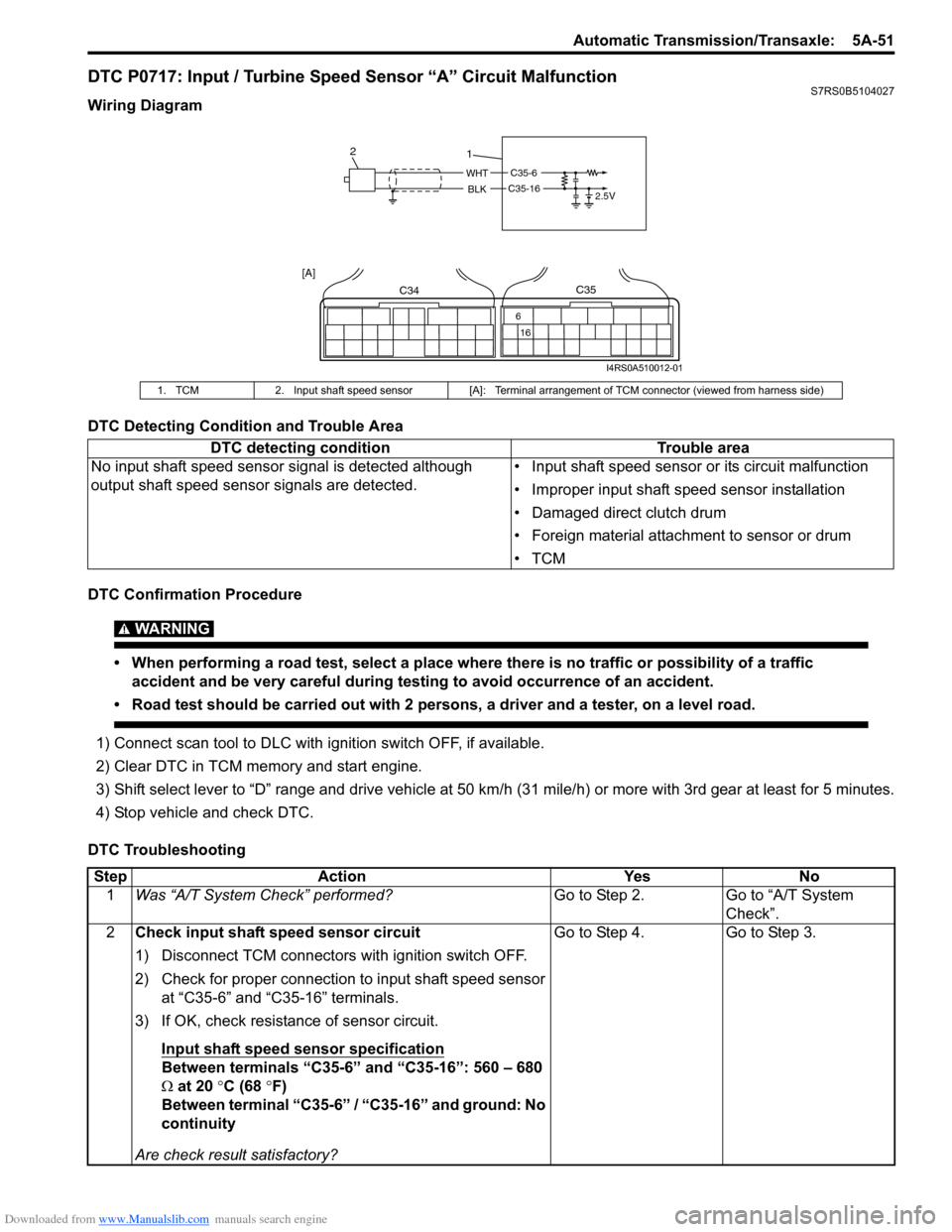
DTC P0717: Input / Turbine Speed Sensor “A” Circuit MalfunctionS7RS0B5104027
Wiring Diagram
DTC Detecting Condition and Trouble Area
DTC Confirmation Procedure
WARNING!
• When performing a road test, select a place where there is no traffic or possibility of a traffic accident and be very careful during testing to avoid occurrence of an accident.
• Road test should be carried out with 2 persons, a driver and a tester, on a level road.
1) Connect scan tool to DLC with ig nition switch OFF, if available.
2) Clear DTC in TCM memory and start engine.
3) Shift select lever to “D” range and drive vehicle at 50 km /h (31 mile/h) or more with 3rd gear at least for 5 minutes.
4) Stop vehicle and check DTC.
DTC Troubleshooting
1. TCM 2. Input shaft speed sensor [A]: Terminal arrangement of TCM connector (viewed from harness side)
DTC detecting condition Trouble area
No input shaft speed sensor signal is detected although
output shaft speed sens or signals are detected. • Input shaft speed sensor or its circuit malfunction
• Improper input shaft speed sensor installation
• Damaged direct clutch drum
• Foreign material attachment to sensor or drum
•TCM
C35-6
2.5VWHT
BLKC35-16
1
2
C34
16
6
C35
[A]
I4RS0A510012-01
Step
Action YesNo
1 Was “A/T System Check” performed? Go to Step 2.Go to “A/T System
Check”.
2 Check input shaft speed sensor circuit
1) Disconnect TCM connectors with ignition switch OFF.
2) Check for proper connection to input shaft speed sensor
at “C35-6” and “C35-16” terminals.
3) If OK, check resistance of sensor circuit.
Input shaft speed sensor specification
Between terminals “C35-6” and “C35-16”: 560 – 680
Ω at 20 °C (68 °F)
Between terminal “C35-6” / “C35-16” and ground: No
continuity
Are check result satisfactory? Go to Step 4. Go to Step 3.
Page 696 of 1496

Downloaded from www.Manualslib.com manuals search engine 5A-52 Automatic Transmission/Transaxle:
DTC P0722: Output Speed Sensor Circuit No SignalS7RS0B5104028
Wiring Diagram
DTC Detecting Condition and Trouble Area
DTC Confirmation Procedure
WARNING!
• When performing a road test, select a place where there is no traffic or possibility of a traffic
accident and be very careful during testing to avoid occurrence of an accident.
• Road test should be carried out with 2 persons, a driver and a tester, on a level road.
3 Inspect input shaft speed sensor
1) Inspect input shaft speed sensor referring to “Input Shaft
Speed Sensor Inspection”.
Is result satisfactory? “WHT” or “BLK” circuit
open or short.
Replace input shaft
speed sensor.
4 Check visually input shaft speed sensor and direct
clutch drum for the following
• No damage
• No foreign material attached
• Correct installation
Are they in good condition? Intermittent trouble or
faulty TCM.
Check for intermittent
referring to “Intermittent
and Poor Connection
Inspection in Section
00”.
If OK, substitute a
known-good TCM and
recheck.
Clean, repair or replace.
Step Action Yes No
I2RH0B510020-01
1. TCM
3. To ECM
2. Output shaft speed sensor [A]: Terminal arrangement of TCM connector (viewed from harness side)
DTC detecting condition Trouble area
No output shaft speed sensor signal is detected although
input shaft speed sensor signal s are detected while vehicle is
running at 5 km/h (3 mile/h) or more in vehicle speed with
“D”, “2” or “L” range. • Output shaft speed sensor or its circuit malfunction
• Damaged sensor gear (driven gear)
• Damaged output shaft speed sensor drive gear
•TCM
IG112V
PPLC35-25
2
C34
25
C35
[A]
1
BLK/RED
BLK/ORN
3
I4RS0B510005-01
Page 719 of 1496

Downloaded from www.Manualslib.com manuals search engine Automatic Transmission/Transaxle: 5A-75
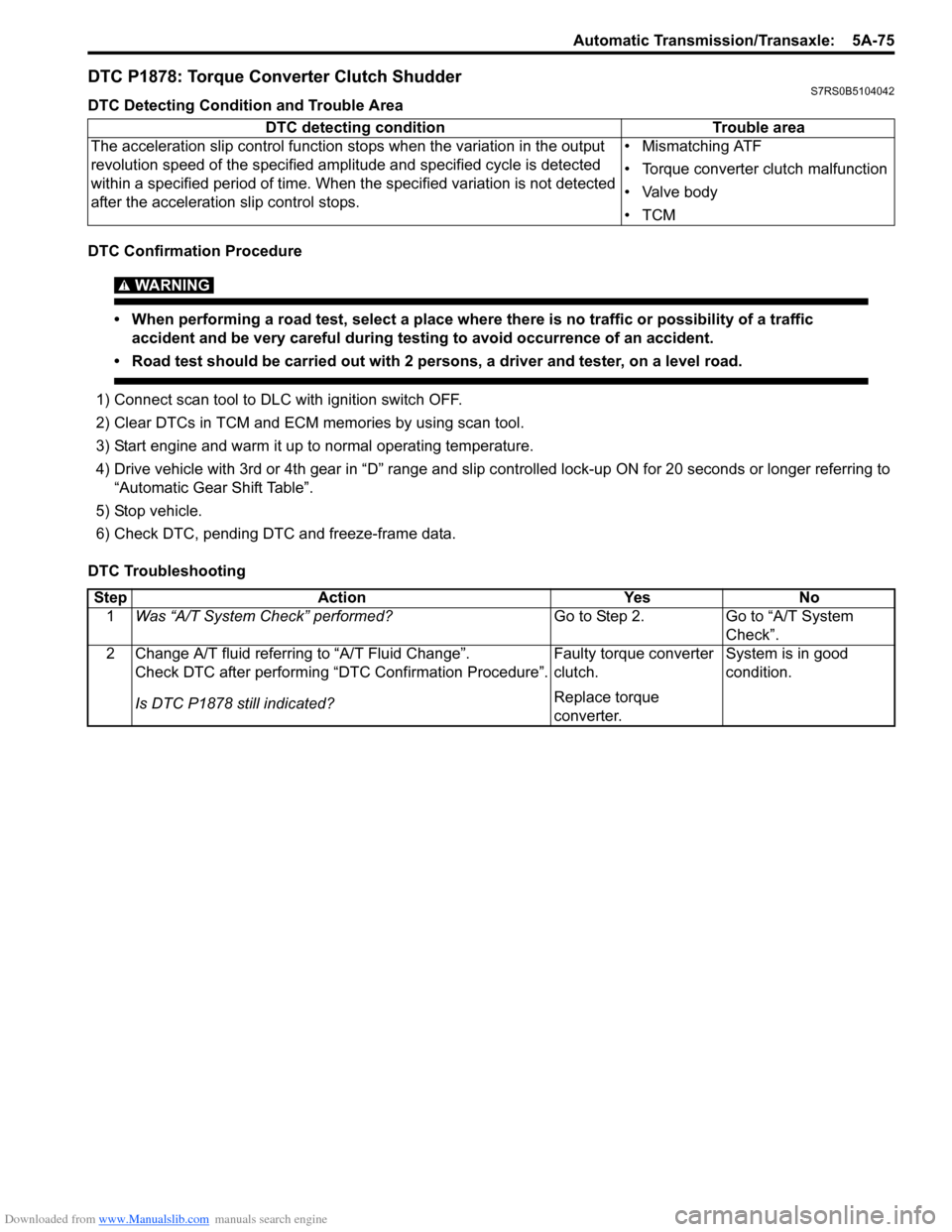
DTC P1878: Torque Converter Clutch ShudderS7RS0B5104042
DTC Detecting Condition and Trouble Area
DTC Confirmation Procedure
WARNING!
• When performing a road test, select a place where there is no traffic or possibility of a traffic accident and be very careful during testing to avoid occurrence of an accident.
• Road test should be carried out with 2 persons, a driver and tester, on a level road.
1) Connect scan tool to DLC with ignition switch OFF.
2) Clear DTCs in TCM and ECM memories by using scan tool.
3) Start engine and warm it up to normal operating temperature.
4) Drive vehicle with 3rd or 4th gear in “D” range and slip c ontrolled lock-up ON for 20 seconds or longer referring to
“Automatic Gear Shift Table”.
5) Stop vehicle.
6) Check DTC, pending DTC and freeze-frame data.
DTC Troubleshooting DTC detecting condition
Trouble area
The acceleration slip control function stops when the variation in the output
revolution speed of the specified amp litude and specified cycle is detected
within a specified period of time. When t he specified variation is not detected
after the acceleration slip control stops. • Mismatching ATF
• Torque converter clutch malfunction
• Valve body
•TCM
Step
Action YesNo
1 Was “A/T System Check” performed? Go to Step 2.Go to “A/T System
Check”.
2 Change A/T fluid referring to “A/T Fluid Change”. Check DTC after performing “DTC Confirmation Procedure”.
Is DTC P1878 still indicated? Faulty torque converter
clutch.
Replace torque
converter.System is in good
condition.
Page 720 of 1496

Downloaded from www.Manualslib.com manuals search engine 5A-76 Automatic Transmission/Transaxle:
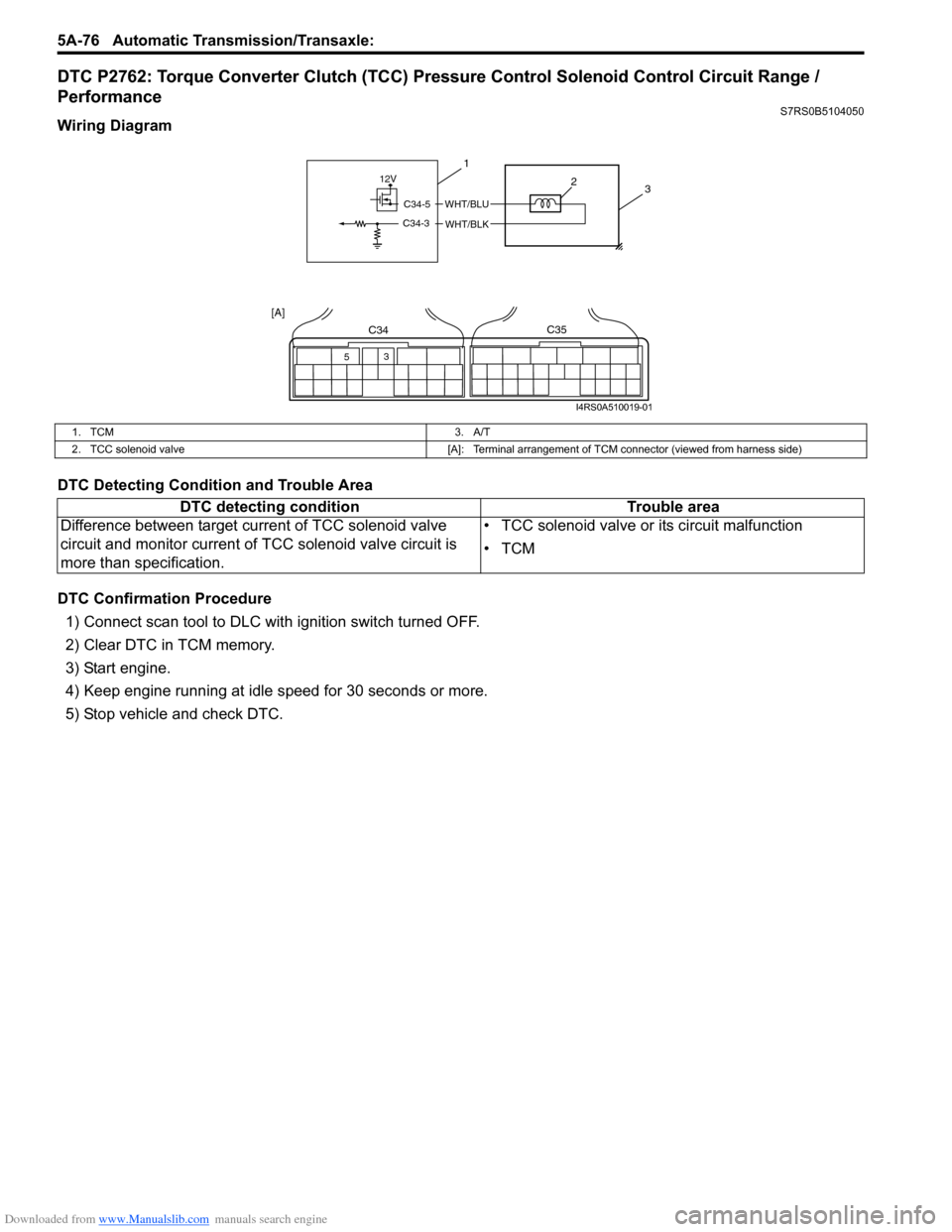
DTC P2762: Torque Converter Clutch (TCC) Pressure Control Solenoid Control Circuit Range /
Performance
S7RS0B5104050
Wiring Diagram
DTC Detecting Condition and Trouble Area
DTC Confirmation Procedure
1) Connect scan tool to DLC with ignition switch turned OFF.
2) Clear DTC in TCM memory.
3) Start engine.
4) Keep engine running at idle speed for 30 seconds or more.
5) Stop vehicle and check DTC.
12V
C34-5
C34-3
WHT/BLU
WHT/BLK
3
1
2
53
C34C35
[A]
I4RS0A510019-01
1. TCM
3. A/T
2. TCC solenoid valve [A]: Terminal arrangement of TCM connector (viewed from harness side)
DTC detecting conditionTrouble area
Difference between target current of TCC solenoid valve
circuit and monitor current of TCC solenoid valve circuit is
more than specification. • TCC solenoid valve or its circuit malfunction
•TCM
Page 722 of 1496

Downloaded from www.Manualslib.com manuals search engine 5A-78 Automatic Transmission/Transaxle:
DTC P2763: Torque Converter Clutch Pressure Control Solenoid Control Circuit HighS7RS0B5104043
Wiring Diagram
DTC Detecting Condition and Trouble Area
DTC Confirmation Procedure
WARNING!
• When performing a road test, select a place where there is no traffic or possibility of a traffic
accident and be very careful during testing to avoid occurrence of an accident.
• Road test should be carried out with 2 persons, a driver and a tester, on a level road.
1) Connect scan tool to DLC with ig nition switch OFF, if available.
2) Clear DTC in TCM memory.
3) Start engine.
4) Keep engine running at idle speed in “P” range for 10 seconds or more.
5) Check DTC.
DTC Troubleshooting
1. TCM 3. A/T
2. TCC lock-up pressure control solenoid valve [A]: Terminal arrangement of TCM connector (viewed from harness side)
DTC detecting conditionTrouble area
Voltage of TCC lock-up pressure control solenoid valve TCM
terminal is high although TCM is commanding TCC lock-up
pressure control sole noid to turn OFF. • TCC lock-up pressure contro
l solenoid valve circuit
shorted to ground
• Malfunction of TCC lock-up pressure control solenoid valve
•TCM
12V
C34-5
C34-3
WHT/BLU
WHT/BLK
3
1
2
53
C34C35
[A]
I4RS0A510019-01
Step
Action YesNo
1 Was “A/T System Check” performed? Go to Step 2.Go to “A/T System
Check”.
Page 724 of 1496

Downloaded from www.Manualslib.com manuals search engine 5A-80 Automatic Transmission/Transaxle:
DTC P2764: Torque Converter Clutch Circuit Pressure Control Solenoid Control Circuit LowS7RS0B5104044
Wiring Diagram
DTC Detecting Condition and Trouble Area
DTC Confirmation Procedure
WARNING!
• When performing a road test, select a place where there is no traffic or possibility of a traffic
accident and be very careful during testing to avoid occurrence of an accident.
• Road test should be carried out with 2 persons, a driver and a tester, on a level road.
1) Connect scan tool to DLC with ig nition switch OFF, if available.
2) Clear DTC in TCM memory.
3) Start engine.
4) Keep engine running at idle speed in “P” range for 20 seconds or more.
5) Check DTC.
DTC Troubleshooting
1. TCM 3. A/T
2. TCC pressure control solenoid valve [A]: Terminal arrangement of TCM connector (viewed from harness side)
DTC detecting condition Trouble area
Voltage of TCC lock-up pressure control solenoid valve TCM
terminal is low although TCM is commanding TCC lock-up
pressure control sole noid to turn ON. • TCC lock-up pressure contro
l solenoid valve circuit
shorted to ground
• Malfunction of TCC lock-up pressure control solenoid valve
•TCM
12V
C34-5
C34-3
WHT/BLU
WHT/BLK
3
1
2
53
C34C35
[A]
I4RS0A510019-01
Step
Action YesNo
1 Was “A/T System Check” performed? Go to Step 2.Go to “A/T System
Check”.
Page 727 of 1496

Downloaded from www.Manualslib.com manuals search engine Automatic Transmission/Transaxle: 5A-83
Connector “C34”Terminal Wire color Circuit Standard
voltage Condition
1 BLK Ground 0 – 1 V Ignition switch ON
2 LT GRN/
BLK Pressure control
solenoid valve (–)
0.6 – 1.0 V Ignition switch ON
3WHT/BLK TCC pressure control
solenoid valve (–) 0.6 – 1.0 V Ignition switch ON
4GRY Pressure control
solenoid valve (+) *0 – 0.6 V
↑↓
10 – 14 V
(“Reference waveform No. 1: ”) Engine running at idling.
(Output signal is duty pulse. Duty ratio varies
depending on throttle valve opening.)
5WHT/BLU TCC pressure control
solenoid valve (+) *0 – 0.6 V
↑↓
10 – 14 V
(“Reference waveform No. 2: ”) Engine running at idling.
(Output signal is duty pulse. Duty ratio varies
depending on torque converter clutch operating
condition.)
6 YEL/BLK Power source 10 – 14 V Ignition switch ON
7WHT CAN communication
line (Low) *2.5 – 3.6 V
↑↓
1.6 – 2.5 V
(“Reference waveform No. 3: ”) Engine running at idling with after warming up.
(CAN communication signal is pulse. Pulse signal
frequency varies depending on engine condition.))
8— — — —
9— — — —
10 — —— —
11 LT G R N Transmission fluid
temperature sensor (+) 2.9 – 3.1 V Ignition switch ON, fluid temperature is 20
°C (68 °F)
0.3 – 0.5 V Ignition switch ON, fluid temperature is 100 °C (212 °F)
12 ORN Transmission fluid
temperature sensor (–) 0 – 1 V Ignition switch ON
13 — —— —
14 BLU/BLK Timing solenoid valv e 0 – 1 V Ignition switch ON
15 BLK/YEL Shift solenoid valve-B
(No.2) 9 – 14 V Ignition switch ON, select lever in “P” range
16 BRN Shift solenoid valve-A
(No.1) 9 – 14 V Ignition switch ON, select lever in “P” range
17 RED CAN communication
line (High) *2.5 – 3.6 V
↑↓
1.6 – 2.5 V
(“Reference waveform No. 3: ”) Engine running at idling with after warming up.
(CAN communication signal is pulse. Pulse signal
frequency varies depending on engine condition.)
18 — —— —
19 — —— —
20 — —— —
21 — —— —
22 — —— —
23 BLK Ground 0 – 1 V Ignition switch ON
24 WHT/RED Power source
for back-
up 10 – 14 V Constantly