Page 1205 of 1496

Downloaded from www.Manualslib.com manuals search engine Wiring Systems: 9A-34
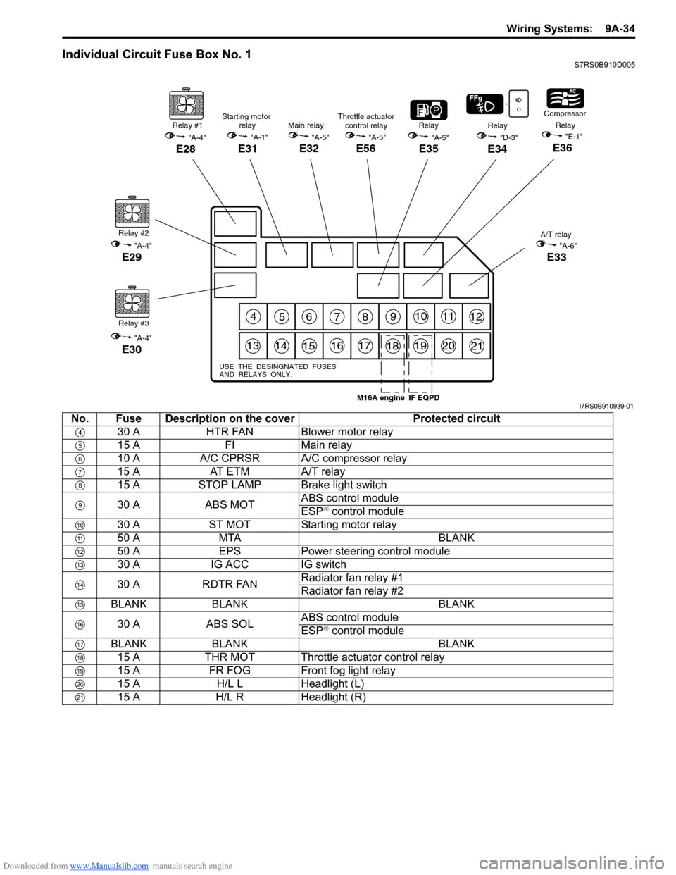
Individual Circuit Fuse Box No. 1S7RS0B910D005
456789101112
131415161718192021
USE THE DESINGNATED FUSES
AND RELAYS ONLY.
Relay #1
"A-4"
E28
Relay #2
"A-4"
E29
Relay #3
"A-4"
E30
"A-5"
E35
RelayRelay
"D-3"
E34
Compressor
Relay"E-1"
E36
A/T relay
"A-6"
E33
Main relay
"A-5"
E32
Starting motor relay
"A-1"
E31
Throttle actuatorcontrol relay
"A-5"
E56
IF EQPDM16A engineI7RS0B910939-01
No. Fuse Description on the cover Protected circuit
30 A HTR FAN Blower motor relay
15 A FIMain relay
10 A A/C CPRSR A/C compressor relay
15 A AT ETM A/T relay
15 A STOP LAMP Brake light switch
30 A ABS MOT ABS control module
ESP
® control module
30 A ST MOT Starting motor relay
50 A MTA BLANK
50 A EPS Power steering control module
30 A IG ACC IG switch
30 A RDTR FAN Radiator fan relay #1
Radiator fan relay #2
BLANK BLANK BLANK
30 A ABS SOL ABS control module
ESP
® control module
BLANK BLANK BLANK 15 A THR MOT Throttle actuator control relay
15 A FR FOG Front fog light relay
15 A H/L L Headlight (L)
15 A H/L R Headlight (R)
Page 1210 of 1496

Downloaded from www.Manualslib.com manuals search engine 9A-39 Wiring Systems:
1IG2FL2
6
Lamp FL (FL BOX)
1A/B CONT4A/B SIG
3K-LINE2A/B SIGNAL
9A/B SIGNAL8K-LINE
2311BCM ;IG1
22D/UL-IN21D/L-IN D/SL-IN
18SECURITY IN6Serial OUT
14TAIL BCM WNG, etc12ANSWER BACK
17RR DEF CONTROL1D/L (+B)
2BCM15DEICER CONTROL
10ACC (BCM)7DOME LP CONT
20GND (POWER)16R-WIP (CONT)
3SIGNAL GND (BCM)
7IG
1LP-L5LP-R
8+B6SW-L
3GND4SW-R
2HAZ
DOME LP POWER5DOME LP DOOR4*3GND (Roof)6HTR4Starter SW1IG 25ACC SW3IG2SW2IG 1
18107G33415G347G3419G341G3412G339G3311G343G342G348G34166G336G345G33810511G3313G344G341G3320G342G339G343G3312G3414G34
10E395E4112E419E4114E411E418E412E4111E413E416E395E3916E417E414E392E399E393E397E3910E41
DEF LP
RR FOG SW DEICER LP
*TAIL SW (Upper)
TAIL SW (HAZ,ASH,ILL) TURN-L
TURN-R
METER (L)
METER (R)
HAZARD SW HORN SW
Serial INF DISP
A/C PANEL
*MTR Power,etc
IMMOBI IG
A/C PANEL
*
*
RADIO, CLOCK
A/B SIGCIGAR
*F-WIP*
*GND (IP)
SIGNAL GND (IP)
*
*
*
IG Coil, etc EPS AT
ABS CONT
BACK (SHIFT) STOP SW
ABS CONT EPI
BUL IN
HORN
FR TURN (R)
FR TURN (L) POSI LP
EPI
DEICER
*F-Washer
F.WIP
HTR Fuse (30A)
ST RLY COIL
4L0515L0516L055L059L05212L0513L0614L067L0615L0614L0511L056L065L068L057L056L0518L053L051L0510L059L0610L061L063L062L068L0611L064L06
SIGNAL GND (FL)
SEAT HEATER
P/W
R-WIP (+) R-WIP (-)*
ACC SOCKET
R/C MIR (ACC)
*
*
*
LUGGAGE LAMPMTA SHIFT LEVER SW
*
*
RR DEF
HTR MIR (L)
HTR MIR (R)
P/W DR
TAIL LP, LICENSE
R-TURN (L)
RR-TURN (R)
D/ULD/L
D-SL
BUL-L
STOP LP
MTA
*
*
IG COIL 15AMETER 10A A/BAG 15A
IG1 SIG 10A ABS 10A
BACK 10A
TAIL 10AD/L 20A
P/WT 20A
RR DEF 20A
DEICER/RR FOG 15A
MTA/HID R 10A
ACC 1 15A
ACC 2 15A
WIPER 15A P/W 30A
*Spare-1
SEAT HTR 15A IG2 SIG 10AST SIG 10A
HAZ-HORN 15A
DIESEL/HID L 10A *Spare-2 RR DEF RLY
DEICER RLY HORN RLY
P-WIP RLY
BLOWER MOTOR RLY
G34 G34
G33
G34
G33
G34 G33
L05
RADIO 15A
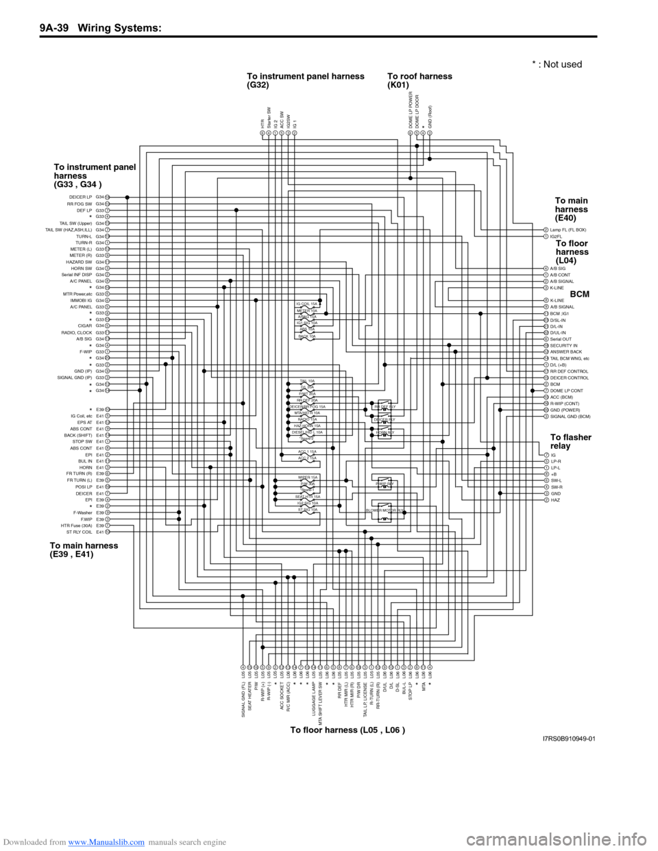
To instrument panel harness
(G32) To roof harness
(K01)
To instrument panel
harness
(G33 , G34 )
To main harness
(E39 , E41) To floor harness (L05 , L06 ) To main
harness
(E40)
BCM
To flasher
relay To floor
harness
(L04)
* : Not used
I7RS0B910949-01
Page 1211 of 1496
Downloaded from www.Manualslib.com manuals search engine Wiring Systems: 9A-40
Junction Block Inner Circuit (Detail)S7RS0B910D009
BCM (J/B side connector)
34
1
2 5
15
14
12
13
10
11
9
8
6
7
17
161821 22
19
20
23
1234578 11 6
12
91034 6 52
1
G33
G32
G34
10
11 12 13 14 15 16 17 18 19 123456789
20
345612K01
23414
3
561214
11
10 157
2113 16
98
6
5
4
3
2
1
7
11
10
9
8
15
14
13
12 16
L04
L06
E41
21
123456789
15 16 17 18
1110 12 13 14
1
234
5 678 910
E39
L05
E40
IMMOBI IG
IG1
IG Coil, etc E39 E41E40
BCM G34G33G32 K01 L04 L05 L06
IG COIL
IG1
15A
METER10A
A/BAG15A
2
6
5
13
J/B Connector No. / Terminal No.
BCM ;IG1
MTR Power, etc
A/B CONT
K-LINE K-LINE
A/B SIGNAL
A/B SIGNAL
A/B SIG
A/B SIG
IG1 SIG 10AEPS AT
ABS CONT
STOP SW
ABS CONT
STOP LP EPI
BUL IN
BUL-L
BACK (SHIFT)
A/C PANEL
6
1
3
2
4
8
11
9
12
9
14
1
2
3
8
2
11
8
ABS
10A
BACK10A
1
(Continued)
Individual circuit fuse box No.2
(In J/B)
23
25
30
29
31
24
I5RS0C910963-02
Page 1246 of 1496
Downloaded from www.Manualslib.com manuals search engine 9A-75 Wiring Systems:
C-3 Combination Meter Circuit Diagram (Warning Light)S7RS0B910E021
J/BMETER
10A25
G2831
3
E24
C3615
G36 E3814
Stepper motor and
LED output driver
Voltage regulator
Interface circuit
Micro controllerEPS
G336
RED/BLK
145293025
PNK/BLKGRY
GRY
RED/BLU
PNK/BLK
BLK/ORN
BLK/ORN
BLK/ORN
RED/BLU
P/S
Cont M
"F-3"
RBPBYBYR
YEL/BLKYEL/RED
A/B
SDM
"F-1""A-5"
ABS
Cont.M
"F-2"
G
CAN
High Low
WHTWHTRED
WHTRED
RED
RW
109 8
6L0114
RED/BLKBRN/YEL
L271
Parking
brake
switch
1
2
A
A
16
BLK/ORN
BLK/ORN
J/C
L24
Seat belt
switch
Oil
pressure switch
E24
C3614
BLU
BLU
1C18
D01
RED/BLK
E021
Brake
fluid
level
switch
and
fuel gauge
2
53
BLK
11 5E46G372
4
RW
W
21WHTRED
"A-5"
1
2
RBBBYRB
7
BCM
ECM"B-9"
KLS
ECM
7
R"B-9"
KLS
ECM
Without seat heater
AWith seat heater
BM13A engine, M15A engine
CM16A engine
D
C
C
C
D
(CAN)
(CAN) (CAN)
(CAN)
L26
L61AB
B
BA
A
J/C
G59
BLU
BLU
D
C18
D022G35 E371419
D
I7RS0B910925-01
Page 1270 of 1496
Downloaded from www.Manualslib.com manuals search engine 9A-99 Wiring Systems:
F-4 Power Steering System Circuit DiagramS7RS0B910E036
P/S
Cont.M
50AEPS12
E4112
J/B
10A IG1 SIG
29
RED
20
E48
E50
E50
E48
Torque sensor
BLK
E49
8
GRN
LT GRN/BLK
YEL
16
GRN
8
BRN
49
WHT
18
BLU
619
1
21
LT GRN/BLK
3
E53
E49
E52
E52
RB
5
ECM
"A-5"
RED/BLU
RED/BLU
14
Individual circuit
fuse box (No.1)
RHD
LHDAB
AB2
6AB6
2AB1
7AB5
3AB7
1
I5RS0C910957-02
Page 1271 of 1496
Downloaded from www.Manualslib.com manuals search engine Wiring Systems: 9A-100
B
P/S
Cont.M
6
J/C
E42
E48
E50
E
D
G35 E37
J/C
E43
E54
M
REDBLK
E51
ECM
"A-5"
GRYBRN
1211
125
GRY
BRN
1 4
E52
PPL
2
P
4
PPL/WHT
PPL/WHT
EPS
METER
10A25
G2831
G336
RED/BLK
25PPL
G20
DLC
4
BLK
A
A
J/C
G15
5
PPL/WHT
PPL/WHT
A
A
J/C
G16
9E46
E38
G3614
E24
C3615
BLK/ORN
5
3
J/B
15A RADIO
40
G335
WHT/RED
BLK/ORN
16
7
B
B
J/C
G17
BLK/ORN
11
BCM
WHT/RED
G37
9
BLK
A
BLK
PW
WHT/BLKRED/BLK
RBWB
"A-8"
14
6
GRY
1
G
BCM
PPL/WHT
RHD
LHDAB
AB1
2AB2
1
(CAN)
IF EQPD
I7RS0B910937-01
Page 1296 of 1496

Downloaded from www.Manualslib.com manuals search engine 9C-1 Instrumentation / Driver Info. / Horn:
Body, Cab and Accessories
Instrumentation / Driver Info. / Horn
Precautions
Precautions in Diagnosing Troubles for Combination MeterS7RS0B9300001
Combination meter uses signals (information) from each control module by CAN communication to control
speedometer, tachometer, engine coolant temp meter, warning light and indicator light (other than air bag warning
light, high beam indicator light, EPS warn ing light and turn signal indicator light). Therefore, check that no DTC is
detected in each module before performing combination me ter symptom diagnosis. If any DTC is detected, correct
trouble indicated by that DTC troubleshooting first.
General Description
CAN Communication System DescriptionS7RS0B9301001
Refer to “CAN Communication System Description in Section 1A” for Can communication system description.
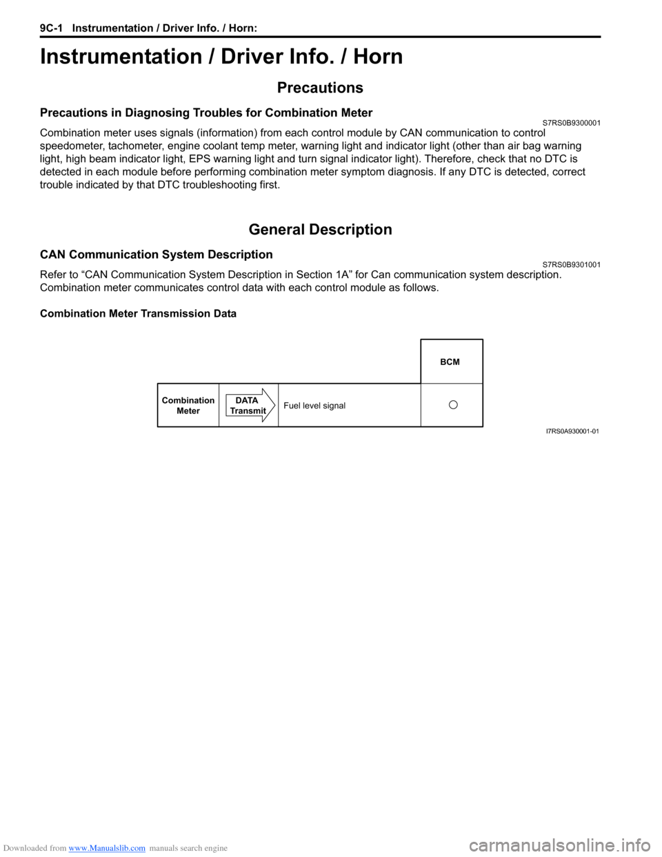
Combination meter communicates control data with each control module as follows.
Combination Meter Transmission Data
BCM
Combination Meter DATA
TransmitFuel level signal
I7RS0A930001-01
Page 1418 of 1496

Downloaded from www.Manualslib.com manuals search engine 10B-15 Body Electrical Control System:
Without Using SUZUKI Scan Tool1) Turn ignition switch to OFF position.
2) Perform following Steps a) to d) within 10 seconds af ter ignition switch is turned ON and engine stops.
a) Turn headlight switch to “SMALL” position.
b) Turn headlight switch to “OFF” position.
c) Repeat Steps a) and b) 2 times.
d) Press and release driver side door switch 3 times.
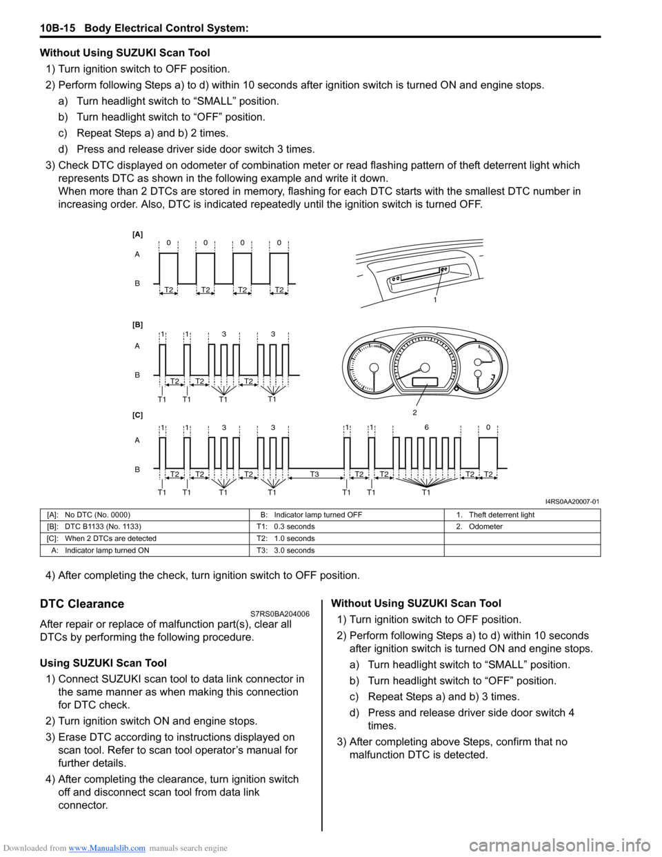
3) Check DTC displayed on odometer of combination meter or read flashing pattern of theft deterrent light which
represents DTC as shown in the following example and write it down.
When more than 2 DTCs are stored in memory, flashing for each DTC starts with the smallest DTC number in
increasing order. Also, DTC is indicated repeatedly until the ignition switch is turned OFF.
4) After completing the check, turn ignition switch to OFF position.
DTC ClearanceS7RS0BA204006
After repair or replace of malfunction part(s), clear all
DTCs by performing the following procedure.
Using SUZUKI Scan Tool 1) Connect SUZUKI scan tool to data link connector in the same manner as when making this connection
for DTC check.
2) Turn ignition switch ON and engine stops.
3) Erase DTC according to instructions displayed on scan tool. Refer to scan tool operator’s manual for
further details.
4) After completing the clear ance, turn ignition switch
off and disconnect scan tool from data link
connector. Without Using SUZUKI Scan Tool
1) Turn ignition switch to OFF position.
2) Perform following Steps a) to d) within 10 seconds after ignition switch is turned ON and engine stops.
a) Turn headlight switch to “SMALL” position.
b) Turn headlight switch to “OFF” position.
c) Repeat Steps a) and b) 3 times.
d) Press and release driver side door switch 4 times.
3) After completing above Steps, confirm that no malfunction DTC is detected.
B A
[B] [A]
[C]
B A B A
3
113
3
113
T2
T1 T1 T1 T1
1
2
T2T2
T2
T1 T1 T1 T1T2T2
0
T2
0
T2
0
T2
0
T2
11 6 0
T1 T1 T1
T2
T3T2T2T2
I4RS0AA20007-01
[A]: No DTC (No. 0000) B: Indicator lamp turned OFF1. Theft deterrent light
[B]: DTC B1133 (No. 1133) T1: 0.3 seconds2. Odometer
[C]: When 2 DTCs are detected T2: 1.0 seconds
A: Indicator lamp tur ned ON T3: 3.0 seconds