2008 SUZUKI SWIFT Section 7b
[x] Cancel search: Section 7bPage 1453 of 1496
Downloaded from www.Manualslib.com manuals search engine Immobilizer Control System: 10C-10
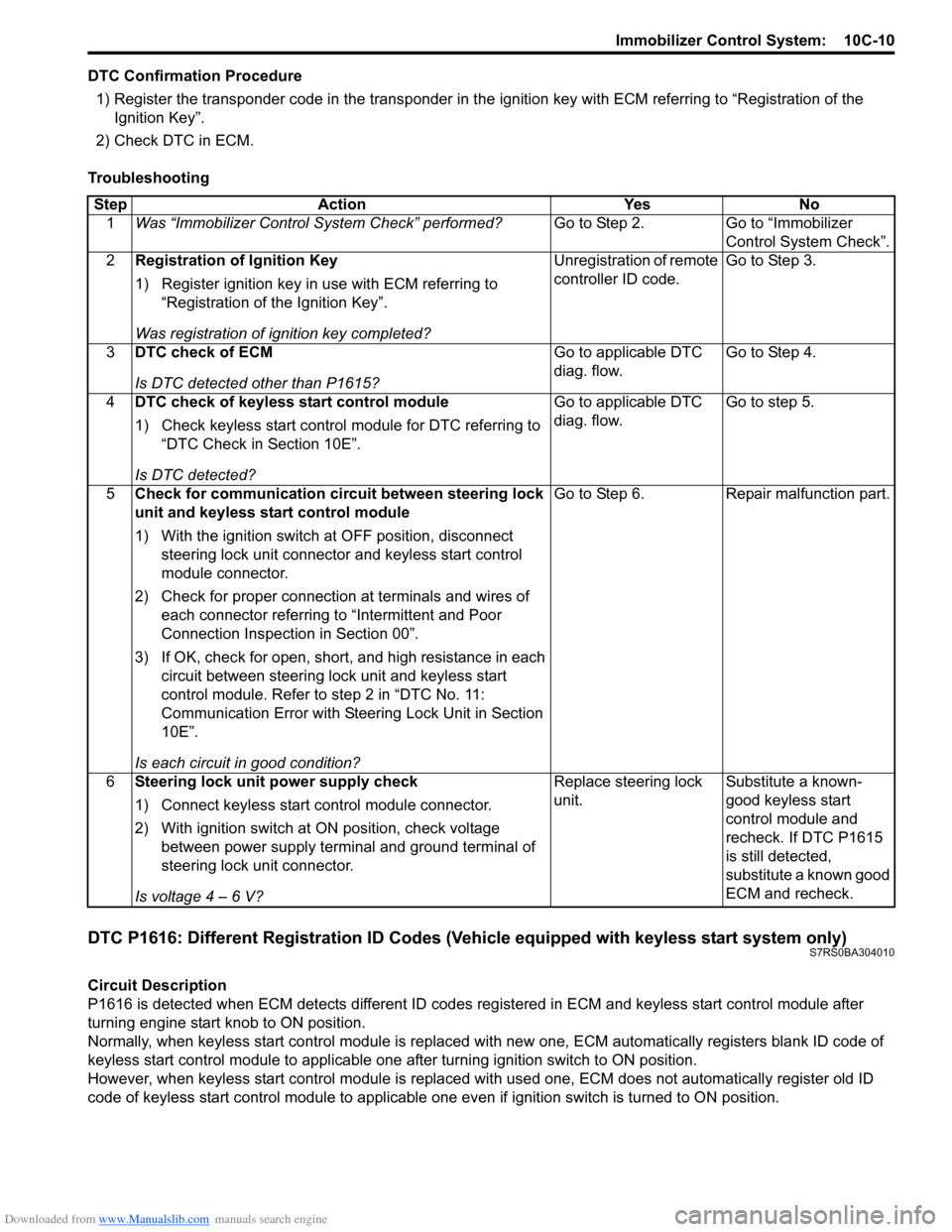
DTC Confirmation Procedure1) Register the transponder code in the transponder in the ignition key with ECM referring to “Registration of the
Ignition Key”.
2) Check DTC in ECM.
Troubleshooting
DTC P1616: Different Registration ID Codes (Vehicle equipped with keyless start system only)S7RS0BA304010
Circuit Description
P1616 is detected when ECM detects different ID codes registered in ECM and keyless start control module after
turning engine start knob to ON position.
Normally, when keyless start control module is replaced with new one, ECM automatically registers blank ID code of
keyless start control module to applicable one after turning ignition switch to ON position.
However, when keyless start control module is replaced wit h used one, ECM does not automatically register old ID
code of keyless start control module to applicable one ev en if ignition switch is turned to ON position.
Step Action Yes No
1 Was “Immobilizer Control S ystem Check” performed? Go to Step 2. Go to “Immobilizer
Control System Check”.
2 Registration of Ignition Key
1) Register ignition key in use with ECM referring to
“Registration of the Ignition Key”.
Was registration of ignition key completed? Unregistration of remote
controller ID code.
Go to Step 3.
3 DTC check of ECM
Is DTC detected other than P1615? Go to applicable DTC
diag. flow.
Go to Step 4.
4 DTC check of keyless start control module
1) Check keyless start control module for DTC referring to
“DTC Check in Section 10E”.
Is DTC detected? Go to applicable DTC
diag. flow.
Go to step 5.
5 Check for communication circuit between steering lock
unit and keyless start control module
1) With the ignition switch at OFF position, disconnect
steering lock unit connector and keyless start control
module connector.
2) Check for proper connection at terminals and wires of
each connector referring to “Intermittent and Poor
Connection Inspection in Section 00”.
3) If OK, check for open, short, and high resistance in each circuit between steering lock unit and keyless start
control module. Refer to step 2 in “DTC No. 11:
Communication Error with Steeri ng Lock Unit in Section
10E”.
Is each circuit in good condition? Go to Step 6. Repair malfunction part.
6 Steering lock unit power supply check
1) Connect keyless start control module connector.
2) With ignition switch at ON position, check voltage
between power supply terminal and ground terminal of
steering lock unit connector.
Is voltage 4 – 6 V? Replace steering lock
unit.
Substitute a known-
good keyless start
control module and
recheck. If DTC P1615
is still detected,
substitute a known good
ECM and recheck.
Page 1455 of 1496
Downloaded from www.Manualslib.com manuals search engine Immobilizer Control System: 10C-12
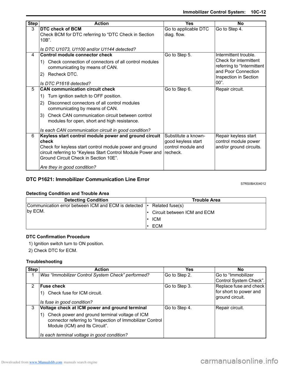
DTC P1621: Immobilizer Communication Line ErrorS7RS0BA304012
Detecting Condition and Trouble Area
DTC Confirmation Procedure1) Ignition switch turn to ON position.
2) Check DTC for ECM.
Troubleshooting 3
DTC check of BCM
Check BCM for DTC referring to “DTC Check in Section
10B”.
Is DTC U1073, U1100 and/or U1144 detected? Go to applicable DTC
diag. flow.
Go to Step 4.
4 Control module connector check
1) Check connection of connectors of all control modules
communicating by means of CAN.
2) Recheck DTC.
Is DTC P1618 detected? Go to Step 5. Intermittent trouble.
Check for intermittent
referring to “Intermittent
and Poor Connection
Inspection in Section
00”.
5 CAN communication circuit check
1) Turn ignition switch to OFF position.
2) Disconnect connectors of all control modules
communicating by means of CAN.
3) Check CAN communication circuit between control modules for open, short and high resistance.
Is each CAN communication circuit in good condition? Go to Step 6. Repair circuit.
6 Keyless start control module power and ground circuit
check
Check for keyless start control module power and ground
circuit referring to “Keyless St art Control Module Power and
Ground Circuit Check in Section 10E”.
Are they in good condition? Substitute a known-
good keyless start
control module and
recheck.
Repair keyless start
control module power
and/or ground circuits.
Step Action Yes No
Detecting Condition
Trouble Area
Communication error between ICM and ECM is detected
by ECM. • Related fuse(s)
• Circuit between ICM and ECM
•ICM
•ECM
Step
Action YesNo
1 Was “Immobilizer Control S ystem Check” performed? Go to Step 2.Go to “Immobilizer
Control System Check”.
2 Fuse check
1) Check fuse for ICM circuit.
Is fuse in good condition? Go to Step 3.
Replace fuse and check
for short to power and
ground circuit.
3 Voltage check at ICM power and ground terminal
1) Check power and ground terminal voltage of ICM
connector referring to “Inspe ction of Immobilizer Control
Module (ICM) and Its Circuit”.
Is each terminal voltage in good condition? Go to Step 4.
Repair circuit.
Page 1456 of 1496
Downloaded from www.Manualslib.com manuals search engine 10C-13 Immobilizer Control System:
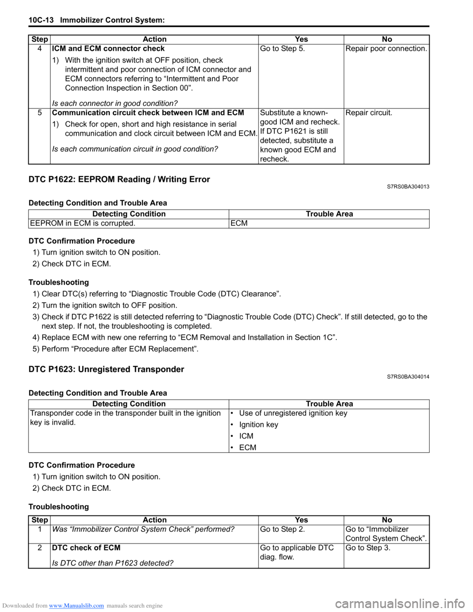
DTC P1622: EEPROM Reading / Writing ErrorS7RS0BA304013
Detecting Condition and Trouble Area
DTC Confirmation Procedure1) Turn ignition switch to ON position.
2) Check DTC in ECM.
Troubleshooting 1) Clear DTC(s) referring to “Diagnostic Trouble Code (DTC) Clearance”.
2) Turn the ignition switch to OFF position.
3) Check if DTC P1622 is still detected re ferring to “Diagnostic Trouble Code (DTC) Check”. If still detected, go to the
next step. If not, the troubleshooting is completed.
4) Replace ECM with new one referring to “ECM Removal and Installation in Section 1C”.
5) Perform “Procedure after ECM Replacement”.
DTC P1623: Unregistered TransponderS7RS0BA304014
Detecting Condition and Trouble Area
DTC Confirmation Procedure 1) Turn ignition switch to ON position.
2) Check DTC in ECM.
Troubleshooting 4
ICM and ECM connector check
1) With the ignition switch at OFF position, check
intermittent and poor connec tion of ICM connector and
ECM connectors referring to “Intermittent and Poor
Connection Inspection in Section 00”.
Is each connector in good condition? Go to Step 5. Repair poor connection.
5 Communication circuit check between ICM and ECM
1) Check for open, short and high resistance in serial
communication and clock circuit between ICM and ECM.
Is each communication circuit in good condition? Substitute a known-
good ICM and recheck.
If DTC P1621 is still
detected, substitute a
known good ECM and
recheck.Repair circuit.
Step Action Yes No
Detecting Condition
Trouble Area
EEPROM in ECM is corrupted. ECM
Detecting Condition Trouble Area
Transponder code in the transponder built in the ignition
key is invalid. • Use of unregistered ignition key
• Ignition key
•ICM
•ECM
Step
Action YesNo
1 Was “Immobilizer Control S ystem Check” performed? Go to Step 2.Go to “Immobilizer
Control System Check”.
2 DTC check of ECM
Is DTC other than P1623 detected? Go to applicable DTC
diag. flow.
Go to Step 3.
Page 1457 of 1496
Downloaded from www.Manualslib.com manuals search engine Immobilizer Control System: 10C-14
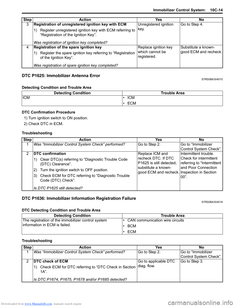
DTC P1625: Immobilizer Antenna ErrorS7RS0BA304015
Detecting Condition and Trouble Area
DTC Confirmation Procedure1) Turn ignition switch to ON position.
2) Check DTC in ECM.
Troubleshooting
DTC P1636: Immobilizer Information Registration FailureS7RS0BA304016
DTC Detecting Condition and Trouble Area
Troubleshooting 3
Registration of unregistered ignition key with ECM
1) Register unregistered igniti on key with ECM referring to
“Registration of the Ignition Key”.
Was registration of ignition key completed? Unregistered ignition
key.
Go to Step 4.
4 Registration of the spare ignition key
1) Register the spare ignition key referring to “Registration
of the Ignition Key”.
Was registration of spare ignition key completed? Replace ignition key
which cannot be
registered.
Substitute a known-
good ECM and recheck.
Step Action Yes No
Detecting Condition
Trouble Area
ICM • ICM
•ECM
StepAction YesNo
1 Was “Immobilizer Control S ystem Check” performed? Go to Step 2.Go to “Immobilizer
Control System Check”.
2 DTC confirmation
1) Clear DTC(s) referring to “Diagnostic Trouble Code
(DTC) Clearance”.
2) Turn the ignition switch to OFF position.
3) Check ECM for DTC referring to “Diagnostic Trouble Code (DTC) Check”.
Is DTC P1625 still detected? Replace ICM and
recheck DTC. If DTC
P1625 is still detected,
substitute a known-
good ECM and recheck.
Intermittent trouble.
Check for intermittent
referring to “Intermittent
and Poor Connection
Inspection in Section
00”.
Detecting Condition
Trouble Area
The registration of the immobilizer control system
information in ECM is failed. • CAN communication wire circuits
•BCM
•ECM
Step
Action YesNo
1 Was “Immobilizer Control S ystem Check” performed? Go to Step 2.Go to “Immobilizer
Control System Check”.
2 DTC check of ECM
1) Check ECM for DTC referring to “DTC Check in Section
1A”.
Is DTC P1674, P1675, P1678 and/or P1685 detected? Go to applicable DTC
diag. flow.
Go to Step 3.
Page 1458 of 1496
Downloaded from www.Manualslib.com manuals search engine 10C-15 Immobilizer Control System:
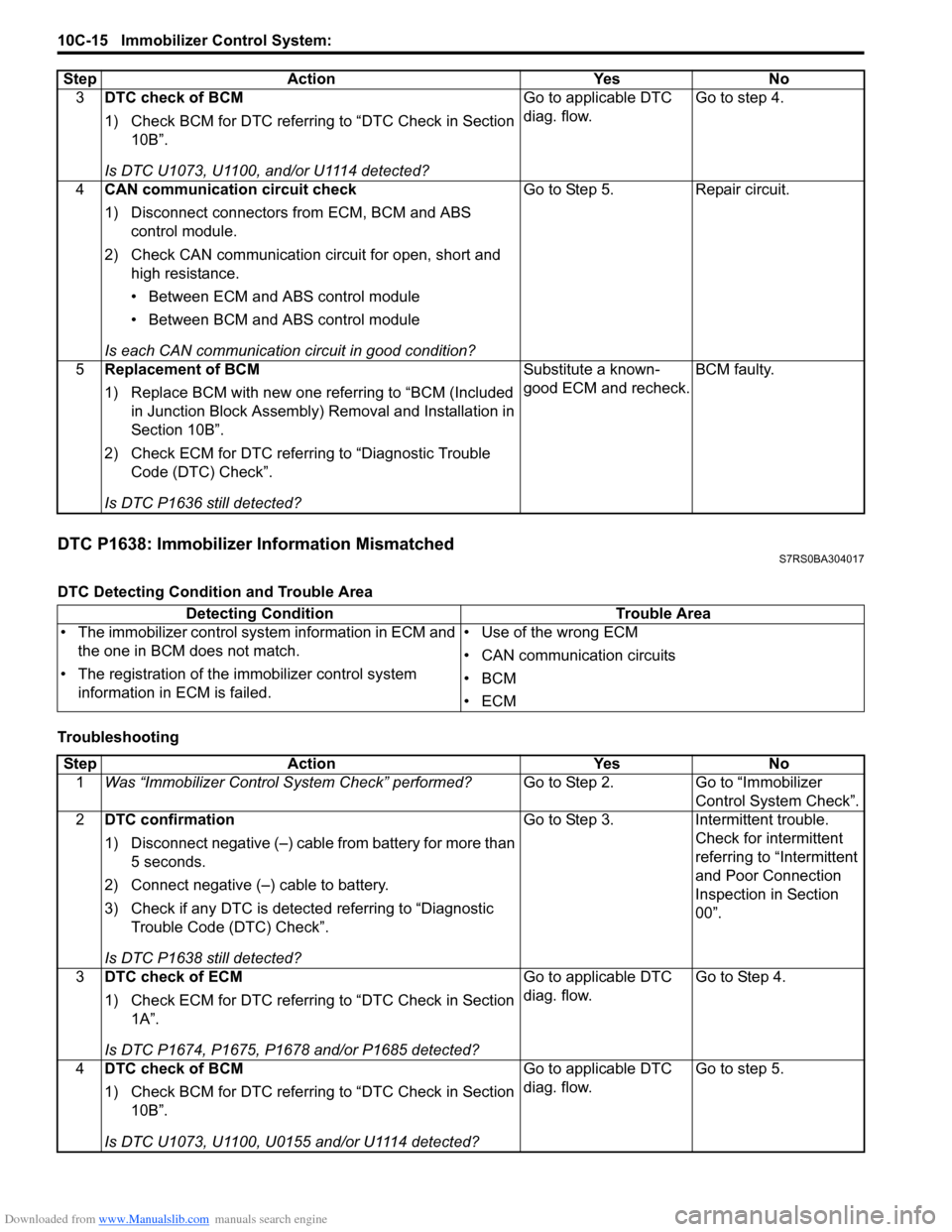
DTC P1638: Immobilizer Information MismatchedS7RS0BA304017
DTC Detecting Condition and Trouble Area
Troubleshooting3
DTC check of BCM
1) Check BCM for DTC referring to “DTC Check in Section
10B”.
Is DTC U1073, U1100, and/or U1114 detected? Go to applicable DTC
diag. flow.
Go to step 4.
4 CAN communication circuit check
1) Disconnect connectors from ECM, BCM and ABS
control module.
2) Check CAN communication circuit for open, short and high resistance.
• Between ECM and ABS control module
• Between BCM and ABS control module
Is each CAN communication circuit in good condition? Go to Step 5. Repair circuit.
5 Replacement of BCM
1) Replace BCM with new one referring to “BCM (Included
in Junction Block Assembly) Removal and Installation in
Section 10B”.
2) Check ECM for DTC referring to “Diagnostic Trouble Code (DTC) Check”.
Is DTC P1636 still detected? Substitute a known-
good ECM and recheck.
BCM faulty.
Step Action Yes No
Detecting Condition
Trouble Area
• The immobilizer control sys tem information in ECM and
the one in BCM does not match.
• The registration of the immobilizer control system
information in ECM is failed. • Use of the wrong ECM
• CAN communication circuits
•BCM
•ECM
Step
Action YesNo
1 Was “Immobilizer Control S ystem Check” performed? Go to Step 2.Go to “Immobilizer
Control System Check”.
2 DTC confirmation
1) Disconnect negative (–) cable from battery for more than
5 seconds.
2) Connect negative (–) cable to battery.
3) Check if any DTC is detecte d referring to “Diagnostic
Trouble Code (DTC) Check”.
Is DTC P1638 still detected? Go to Step 3.
Intermittent trouble.
Check for intermittent
referring to “Intermittent
and Poor Connection
Inspection in Section
00”.
3 DTC check of ECM
1) Check ECM for DTC referring to “DTC Check in Section
1A”.
Is DTC P1674, P1675, P1678 and/or P1685 detected? Go to applicable DTC
diag. flow.
Go to Step 4.
4 DTC check of BCM
1) Check BCM for DTC referring to “DTC Check in Section
10B”.
Is DTC U1073, U1100, U0155 and/or U1114 detected? Go to applicable DTC
diag. flow.
Go to step 5.
Page 1459 of 1496
Downloaded from www.Manualslib.com manuals search engine Immobilizer Control System: 10C-16
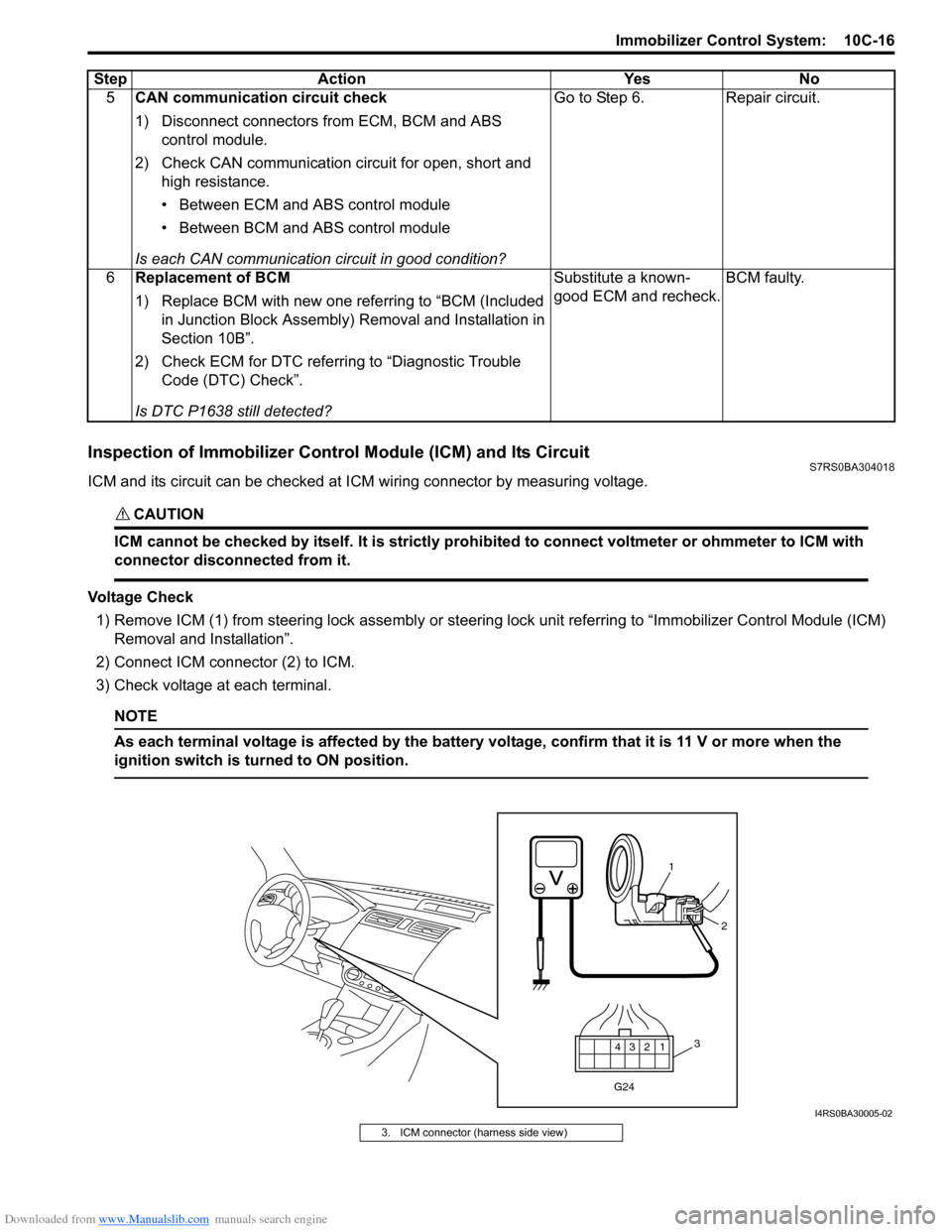
Inspection of Immobilizer Control Module (ICM) and Its CircuitS7RS0BA304018
ICM and its circuit can be checked at ICM wiring connector by measuring voltage.
CAUTION!
ICM cannot be checked by itself. It is strictly prohibited to connect voltmeter or ohmmeter to ICM with
connector disconnected from it.
Voltage Check
1) Remove ICM (1) from steering lock assembly or steering lock unit referrin g to “Immobilizer Control Module (ICM)
Removal and Installation”.
2) Connect ICM connector (2) to ICM.
3) Check voltage at each terminal.
NOTE
As each terminal voltage is affected by the battery voltage, confirm that it is 11 V or more when the
ignition switch is turned to ON position.
5 CAN communication circuit check
1) Disconnect connectors from ECM, BCM and ABS
control module.
2) Check CAN communication circuit for open, short and high resistance.
• Between ECM and ABS control module
• Between BCM and ABS control module
Is each CAN communication circuit in good condition? Go to Step 6. Repair circuit.
6 Replacement of BCM
1) Replace BCM with new one referring to “BCM (Included
in Junction Block Assembly) Removal and Installation in
Section 10B”.
2) Check ECM for DTC referring to “Diagnostic Trouble Code (DTC) Check”.
Is DTC P1638 still detected? Substitute a known-
good ECM and recheck.
BCM faulty.
Step Action Yes No
12
3
4
G24
1
2
3
I4RS0BA30005-02
3. ICM connector (harness side view)
Page 1461 of 1496
Downloaded from www.Manualslib.com manuals search engine Immobilizer Control System: 10C-18
Repair Instructions
Immobilizer Control Module (ICM) Removal and
Installation
S7RS0BA306001
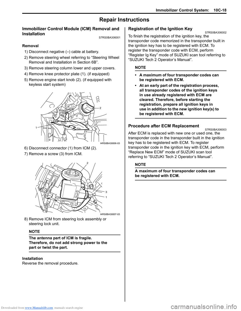
Removal1) Disconnect negative (–) cable at battery.
2) Remove steering wheel referring to “Steering Wheel Removal and Installa tion in Section 6B”.
3) Remove steering column lower and upper covers.
4) Remove knee protector plate (1). (if equipped)
5) Remove engine start knob (2). (if equipped with keyless start system)
6) Disconnect connector (1) from ICM (2).
7) Remove a screw (3) from ICM.
8) Remove ICM from steering lock assembly or steering lock unit.
NOTE
The antenna part of ICM is fragile.
Therefore, do not add strong power to the
part or twist the part.
Installation
Reverse the removal procedure.
Registration of the Ignition KeyS7RS0BA306002
To finish the registration of the ignition key, the
transponder code memorized in the transponder built in
the ignition key has to be registered with ECM. To
register the transponder code with ECM, perform
“Register Ig Key” mode of SU ZUKI scan tool referring to
“SUZUKI Tech 2 Operator’s Manual”.
NOTE
• A maximum of four transponder codes can be registered with ECM.
• At an early part of the registration process, all transponder codes of the ignition keys
in use already registered with ECM are
cleared. Therefore, before starting the
registration, prepare all ignition keys in
use in addition to the new ignition key(s) to
be registered with ECM.
Procedure after ECM ReplacementS7RS0BA306003
After ECM is replaced with new one or used one, the
transponder code in the transponder built in the ignition
key has to be registered with ECM. To register
transponder code in the ignition key with ECM, perform
“Replace New ECM” mode of SUZUKI scan tool
referring to “SUZUKI Tech 2 Operator’s Manual”.
NOTE
A maximum of four transponder codes can
be registered with ECM.
2
1
I4RS0BA30006-03
2
3
1
I4RS0BA30007-03
Page 1468 of 1496
Downloaded from www.Manualslib.com manuals search engine 10E-6 Keyless Start System:
Alarm FunctionS7RS0BA501006
Under conditions as described in the table below, the keyless start control module makes the key indicator lamp flash
in red and the buzzer sound to call the driver’s attention.
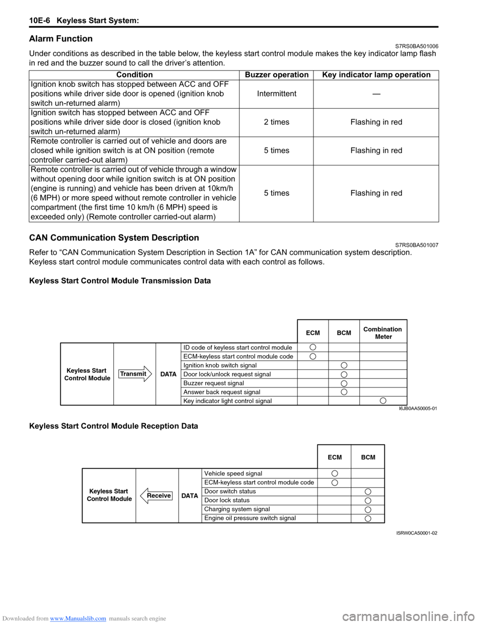
CAN Communication System DescriptionS7RS0BA501007
Refer to “CAN Communication System Description in Section 1A” for CAN communication system description.
Keyless start control module communicates control data wit h each control as follows.
Keyless Start Control Module Transmission Data
Keyless Start Control Module Reception Data Condition Buzzer operation Key indicator lamp operation
Ignition knob switch has stopped between ACC and OFF
positions while driver side door is opened (ignition knob
switch un-returned alarm) Intermittent —
Ignition switch has stopped between ACC and OFF
positions while driver side door is closed (ignition knob
switch un-returned alarm) 2 times Flashing in red
Remote controller is carried out of vehicle and doors are
closed while ignition switch is at ON position (remote
controller carried-out alarm) 5 times Flashing in red
Remote controller is carried out of vehicle through a window
without opening door while ignition switch is at ON position
(engine is running) and vehicle has been driven at 10km/h
(6 MPH) or more speed without remote controller in vehicle
compartment (the first time 10 km/h (6 MPH) speed is
exceeded only) (Remote cont roller carried-out alarm) 5 times Flashing in red
BCM
ECM Combination
Meter
ID code of keyless start control module
ECM-keyless start control module code
Ignition knob switch signal
Door lock/unlock request signal
Buzzer request signal
Answer back request signal
Key indicator light control signal
DATA
Transmit
Keyless Start
Control Module
I6JB0AA50005-01
Vehicle speed signal
ECM-keyless start control module code
Door switch status
Door lock status
Charging system signal
Engine oil pressure switch signal ECM BCM
DATA
ReceiveKeyless Start
Control Module
I5RW0CA50001-02