2008 SUZUKI SWIFT exhaust system
[x] Cancel search: exhaust systemPage 387 of 1496

Downloaded from www.Manualslib.com manuals search engine Fuel System: 1G-12
Fuel Tank Inlet Valve InspectionS7RS0B1706012
WARNING!
Before starting the following procedure, be
sure to observe “Precautions on Fuel System
Service” in order to reduce the risk or fire
and personal injury.
Check fuel tank inlet valve for the following.
If any damage or malfunction is found, replace.
•Damage
• Smooth opening and closing
Fuel Tank Removal and InstallationS7RS0B1706013
WARNING!
Before starting the following procedure, be
sure to observe “Precautions on Fuel System
Service” in order to reduce the risk or fire
and personal injury.
Removal1) Relieve fuel pressure in fuel feed line according to
“Fuel Pressure Relief Procedure”.
2) Disconnect negative cable at battery.
3) Hoist vehicle.
4) Remove exhaust center pipe.
5) Disconnect fuel filler hose and breather hose from
filler neck referring to “Fue l Tank Inlet Valve Removal
and Installation”.
6) Due to absence of fuel tank drain plug, drain fuel tank by pumping fuel out through fuel tank filler.
Use hand operated pump device to drain fuel tank.
CAUTION!
• Do not force pump hose into fuel tank, or pump hose may damage fuel tank inlet
valve.
• Never store fuel in an open container due to possibility of fire or explosion.
7) Disconnect fuel pipe joint and fuel hoses (1) from fuel pipes (2) referring to “Fuel Hose Disconnecting
and Reconnecting”.
8) Support fuel tank (1) with jack (2) and remove its mounting bolts.
9) Lower fuel tank a little as to disconnect wire harness at connector (1) and ground wire (2), then remove
fuel tank.
I2RH0B170019-01
12
I4RS0A170008-01
12
I4RS0A170009-01
1
2
I6RS0C170005-02
Page 388 of 1496

Downloaded from www.Manualslib.com manuals search engine 1G-13 Fuel System:
Installation
CAUTION!
• When connecting joint, clean outside surfaces of pipe where joint is to be
inserted, push joint into pipe till joint lock
clicks and check to ensure that pipes are
connected securely, or fuel leak may
occur.
• Never let the fuel hoses touch the ABS sensor harness (if equipped).
1) If parts have been removed from fuel tank, install them before installing fuel tank to vehicle.
2) Raise fuel tank (1) with jack (2) and connect fuel pump connector (3), ground wire (4) and clamp wire
harness.
Tightening torque
Ground wire bolt (a): 11 N·m (1.1 kgf-m, 8.0 lb-ft)
3) Install fuel tank to vehicle. Tightening torque
Fuel tank bolt (b): 45 N·m (4.5 kgf-m, 33.0 lb-ft) 4) Connect fuel filler hose (1
) and breather hose (2) to
filler neck (3) as shown in figure, and clamp them
securely.
Tightening torque
Fuel filler hose clamp (a): 2 N·m (0.2 kgf-m, 1.5
lb-ft)
5) Connect fuel feed hose (1) and vapor hose (2) to each pipe as shown in figure, and clamp them
securely.
6) Install exhaust center pipe referring to “Exhaust Pipe and Muffler Removal and Installation in Section 1K”.
7) Connect negative cable at battery.
8) With engine OFF, turn ignition switch to ON position and check for fuel leaks.
Fuel Tank InspectionS7RS0B1706014
After removing fuel tank, check hoses and pipes
connected to fuel tank for leaks, loose connections,
deterioration or damage. Also check fuel pump
assembly gaskets for leaks, visually inspect fuel tank for
leaks and damage.
Replace any damaged or malconditioned parts.
(b)(b)
1
2
3
4
(a)
I6RS0C170006-02
1
2
(a)
3
I4RS0A170012-01
1
2
I4RS0A170013-01
Page 416 of 1496
Downloaded from www.Manualslib.com manuals search engine 1J-6 Charging System:
Generator Test (Overcharged Battery Check)S7RS0B1A04004
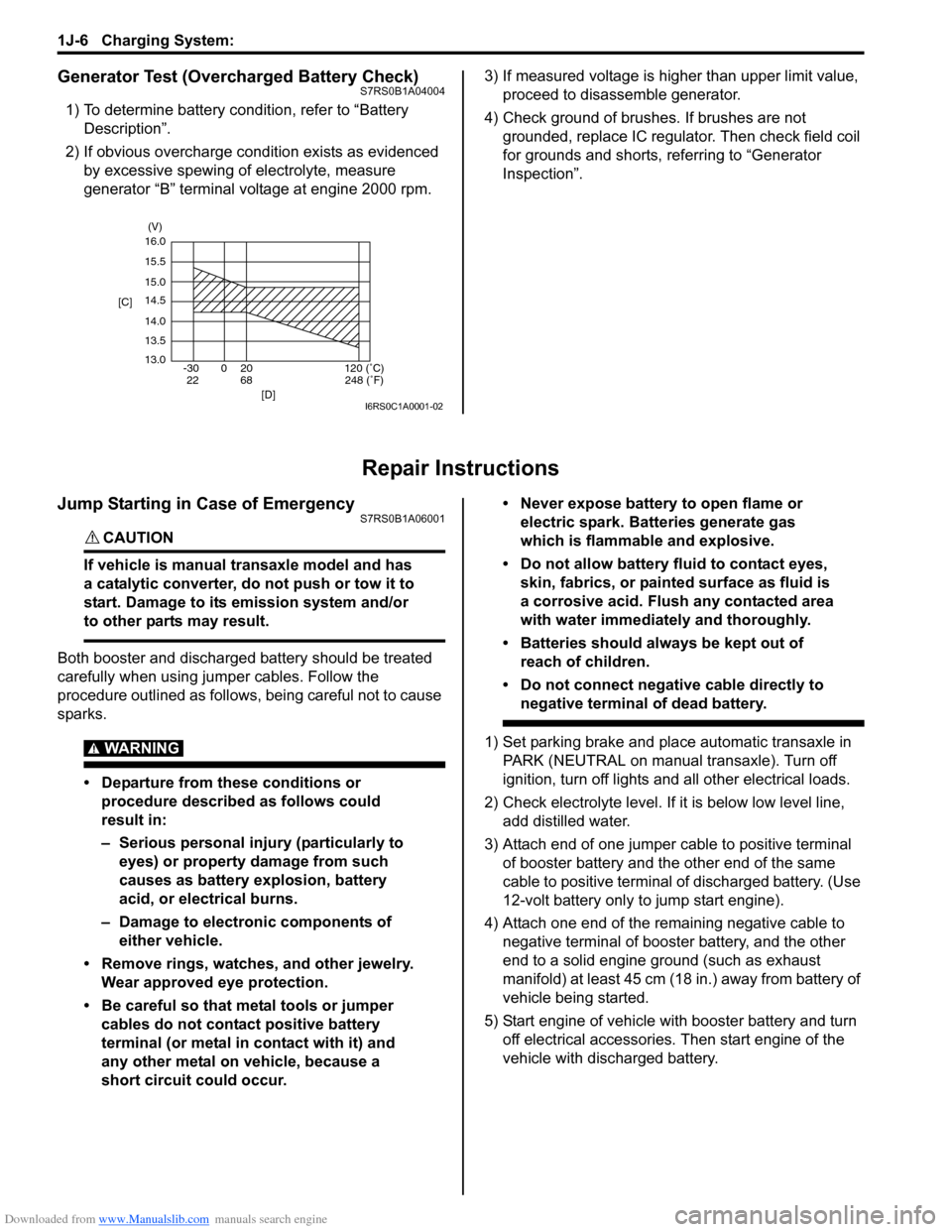
1) To determine battery condition, refer to “Battery Description”.
2) If obvious overcharge condition exists as evidenced by excessive spewing of electrolyte, measure
generator “B” terminal voltage at engine 2000 rpm. 3) If measured voltage is higher than upper limit value,
proceed to disassemble generator.
4) Check ground of brushes. If brushes are not grounded, replace IC regulator. Then check field coil
for grounds and shorts, referring to “Generator
Inspection”.
Repair Instructions
Jump Starting in Case of EmergencyS7RS0B1A06001
CAUTION!
If vehicle is manual transaxle model and has
a catalytic converter, do not push or tow it to
start. Damage to its emission system and/or
to other parts may result.
Both booster and discharged battery should be treated
carefully when using ju mper cables. Follow the
procedure outlined as follows, being careful not to cause
sparks.
WARNING!
• Departure from these conditions or procedure described as follows could
result in:
– Serious personal injury (particularly to eyes) or property damage from such
causes as battery explosion, battery
acid, or electrical burns.
– Damage to electronic components of either vehicle.
• Remove rings, watches, and other jewelry. Wear approved eye protection.
• Be careful so that metal tools or jumper cables do not contact positive battery
terminal (or metal in contact with it) and
any other metal on vehicle, because a
short circuit could occur. • Never expose battery to open flame or
electric spark. Batteries generate gas
which is flammable and explosive.
• Do not allow battery fluid to contact eyes, skin, fabrics, or painted surface as fluid is
a corrosive acid. Flush any contacted area
with water immediately and thoroughly.
• Batteries should always be kept out of reach of children.
• Do not connect negative cable directly to negative terminal of dead battery.
1) Set parking brake and place automatic transaxle in PARK (NEUTRAL on manual transaxle). Turn off
ignition, turn off lights and all other electrical loads.
2) Check electrolyte level. If it is below low level line, add distilled water.
3) Attach end of one jumper cable to positive terminal of booster battery and the other end of the same
cable to positive terminal of discharged battery. (Use
12-volt battery only to jump start engine).
4) Attach one end of the remaining negative cable to negative terminal of booster battery, and the other
end to a solid engine ground (such as exhaust
manifold) at least 45 cm (18 in.) away from battery of
vehicle being started.
5) Start engine of vehicle with booster battery and turn off electrical accessories. Then start engine of the
vehicle with discharged battery.
16.0
15.5
15.0
14.5
14.0
13.5
13.0 -30 0 20
[C]
[D]
68
22120 (˚C)
248 (˚F)
(V)
I6RS0C1A0001-02
Page 424 of 1496
Downloaded from www.Manualslib.com manuals search engine 1K-1 Exhaust System:
Engine
Exhaust System
General Description
Exhaust System DescriptionS7RS0B1B01001
The exhaust system consists of an exhaust manifold, three-way catalytic converter (TWC) in catalyst case, exhaust
pipes, a muffler and seals, gasket and etc.
The three-way catalytic converter is an emission control device added to the exhaust system to lower the levels of
Hydrocarbon (HC), Carbon Monoxide (CO), and Oxides of Nitrogen (NOx) pollutants in the exhaust gas.
Diagnostic Information and Procedures
Exhaust System CheckS7RS0B1B04001
WARNING!
To avoid the danger of being burned, do not touch the exhaust system when the system is hot. Any
service on the exhaust system should be performed when the system is cool.
At every interval of periodic maintenance service, and when vehicle is raised for other service, check exhaust system
as follows:
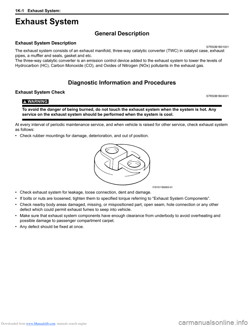
• Check rubber mountings for damage, deterioration, and out of position.
• Check exhaust system for leakage, loose connection, dent and damage.
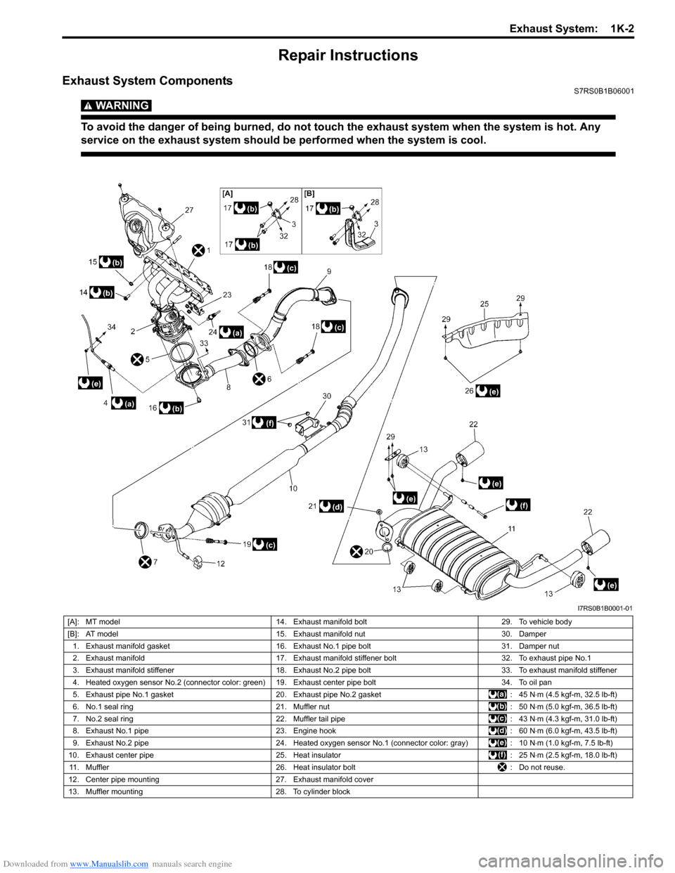
• If bolts or nuts are loosened, tighten them to specified torque referring to “Exhaust System Components”.
• Check nearby body areas damaged, missing, or mispositio ned part, open seam, hole connection or any other
defect which could permit exhaust fumes to seep into vehicle.
• Make sure that exhaust system components have enough clearance from underbody to avoid overheating and
possible damage to passenger compartment carpet.
• Any defect should be fixed at once.
IYSY011B0003-01
Page 425 of 1496
Downloaded from www.Manualslib.com manuals search engine Exhaust System: 1K-2
Repair Instructions
Exhaust System ComponentsS7RS0B1B06001
WARNING!
To avoid the danger of being burned, do not touch the exhaust system when the system is hot. Any
service on the exhaust system should be performed when the system is cool.
I7RS0B1B0001-01
[A]: MT model14. Exhaust manifold bolt 29. To vehicle body
[B]: AT model 15. Exhaust manifold nut 30. Damper
1. Exhaust manifold gasket 16. Exhaust No.1 pipe bolt 31. Damper nut
2. Exhaust manifold 17. Exhaust manifold stiffener bolt 32. To exhaust pipe No.1
3. Exhaust manifold stiffener 18. Exhaust No.2 pipe bolt 33. To exhaust manifold stiffener
4. Heated oxygen sensor No.2 (connector color: green) 19. Exhaust center pipe bolt 34. To oil pan
5. Exhaust pipe No.1 gasket 20. Exhaust pipe No.2 gasket : 45 N⋅m (4.5 kgf-m, 32.5 lb-ft)
6. No.1 seal ring 21. Muffler nut : 50 N⋅m (5.0 kgf-m, 36.5 lb-ft)
7. No.2 seal ring 22. Muffler tail pipe : 43 N⋅m (4.3 kgf-m, 31.0 lb-ft)
8. Exhaust No.1 pipe 23. Engine hook : 60 N⋅m (6.0 kgf-m, 43.5 lb-ft)
9. Exhaust No.2 pipe 24. Heated oxygen sensor No.1 (connector color: gray) : 10 N⋅m (1.0 kgf-m, 7.5 lb-ft)
10. Exhaust center pipe 25. Heat insulator : 25 N⋅m (2.5 kgf-m, 18.0 lb-ft)
11. Muffler 26. Heat insulator bolt : Do not reuse.
12. Center pipe mounting 27. Exhaust manifold cover
13. Muffler mounting 28. To cylinder block
Page 426 of 1496
Downloaded from www.Manualslib.com manuals search engine 1K-3 Exhaust System:
Exhaust Manifold Removal and InstallationS7RS0B1B06002
Removal
WARNING!
To avoid danger of being burned, do not
service exhaust system while it is still hot.
Service should be performed after system
cools down.
1) Disconnect negative cable at battery.
2) Remove engine cover.
3) Remove front bumper with front grille referring to
“Front Bumper and Rear Bumper Components in
Section 9K”.
4) Remove radiator referring to “Radiator Removal and Installation in Section 1F ” for equipped with A/C.
5) With hose connected, detach A/C condenser from vehicle body for equipped with A/C.
6) Remove exhaust manifold cover from exhaust manifold.
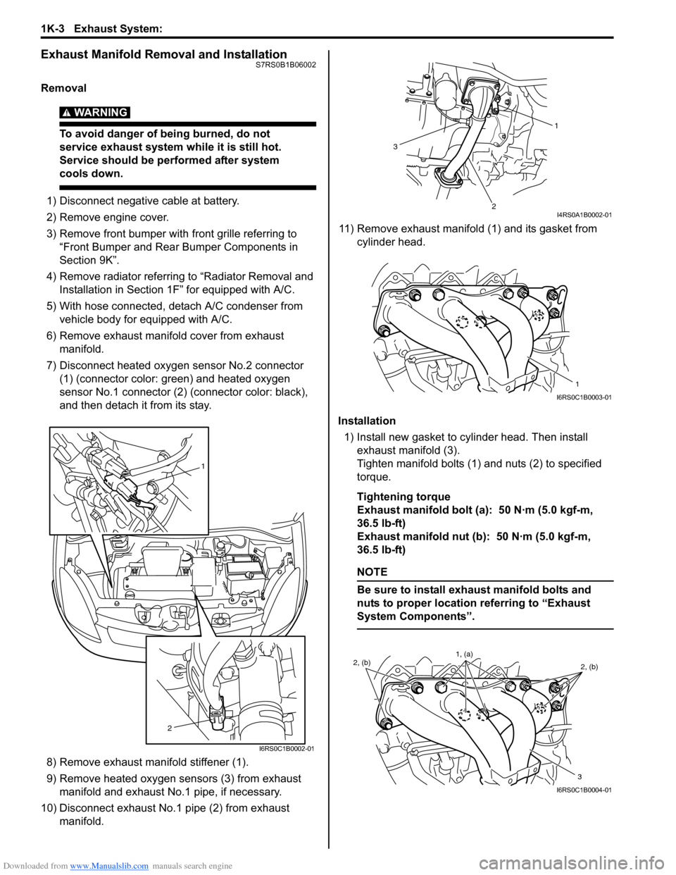
7) Disconnect heated oxygen sensor No.2 connector (1) (connector color: green) and heated oxygen
sensor No.1 connector (2) (connector color: black),
and then detach it from its stay.
8) Remove exhaust manifold stiffener (1).
9) Remove heated oxygen sensors (3) from exhaust manifold and exhaust No.1 pipe, if necessary.
10) Disconnect exhaust No.1 pipe (2) from exhaust manifold. 11) Remove exhaust manifold (1) and its gasket from
cylinder head.
Installation 1) Install new gasket to cylinder head. Then install exhaust manifold (3).
Tighten manifold bolts (1) and nuts (2) to specified
torque.
Tightening torque
Exhaust manifold bolt (a): 50 N·m (5.0 kgf-m,
36.5 lb-ft)
Exhaust manifold nut (b): 50 N·m (5.0 kgf-m,
36.5 lb-ft)
NOTE
Be sure to install exhaust manifold bolts and
nuts to proper location referring to “Exhaust
System Components”.
1
2
I6RS0C1B0002-01
1
2
3
I4RS0A1B0002-01
1
I6RS0C1B0003-01
2, (b) 2, (b)
3
1, (a)
I6RS0C1B0004-01
Page 427 of 1496
Downloaded from www.Manualslib.com manuals search engine Exhaust System: 1K-4
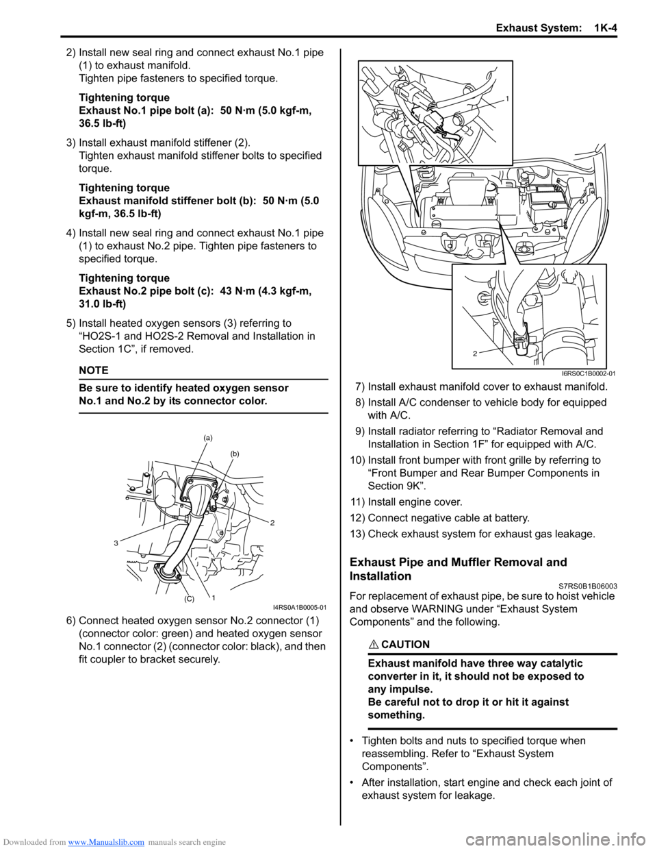
2) Install new seal ring and connect exhaust No.1 pipe (1) to exhaust manifold.
Tighten pipe fasteners to specified torque.
Tightening torque
Exhaust No.1 pipe bolt (a): 50 N·m (5.0 kgf-m,
36.5 lb-ft)
3) Install exhaust manifold stiffener (2). Tighten exhaust manifold stiffener bolts to specified
torque.
Tightening torque
Exhaust manifold stiffener bolt (b): 50 N·m (5.0
kgf-m, 36.5 lb-ft)
4) Install new seal ring and connect exhaust No.1 pipe (1) to exhaust No.2 pipe. Tighten pipe fasteners to
specified torque.
Tightening torque
Exhaust No.2 pipe bolt (c): 43 N·m (4.3 kgf-m,
31.0 lb-ft)
5) Install heated oxygen sensors (3) referring to “HO2S-1 and HO2S-2 Removal and Installation in
Section 1C”, if removed.
NOTE
Be sure to identify heated oxygen sensor
No.1 and No.2 by its connector color.
6) Connect heated oxygen sensor No.2 connector (1)
(connector color: green) and heated oxygen sensor
No.1 connector (2) (connector color: black), and then
fit coupler to br acket securely. 7) Install exhaust manifold cover to exhaust manifold.
8) Install A/C condenser to vehicle body for equipped
with A/C.
9) Install radiator referrin g to “Radiator Removal and
Installation in Section 1F” for equipped with A/C.
10) Install front bumper with fr ont grille by referring to
“Front Bumper and Rear Bumper Components in
Section 9K”.
11) Install engine cover.
12) Connect negative cable at battery.
13) Check exhaust system for exhaust gas leakage.
Exhaust Pipe and Muffler Removal and
Installation
S7RS0B1B06003
For replacement of exhaust pipe, be sure to hoist vehicle
and observe WARNING under “Exhaust System
Components” and the following.
CAUTION!
Exhaust manifold have three way catalytic
converter in it, it should not be exposed to
any impulse.
Be careful not to drop it or hit it against
something.
• Tighten bolts and nuts to specified torque when reassembling. Refer to “Exhaust System
Components”.
• After installation, start engine and check each joint of exhaust system for leakage.
2
(b)
(a)
1(C)
3
I4RS0A1B0005-01
1
2
I6RS0C1B0002-01
Page 428 of 1496
Downloaded from www.Manualslib.com manuals search engine 1K-5 Exhaust System:
Specifications
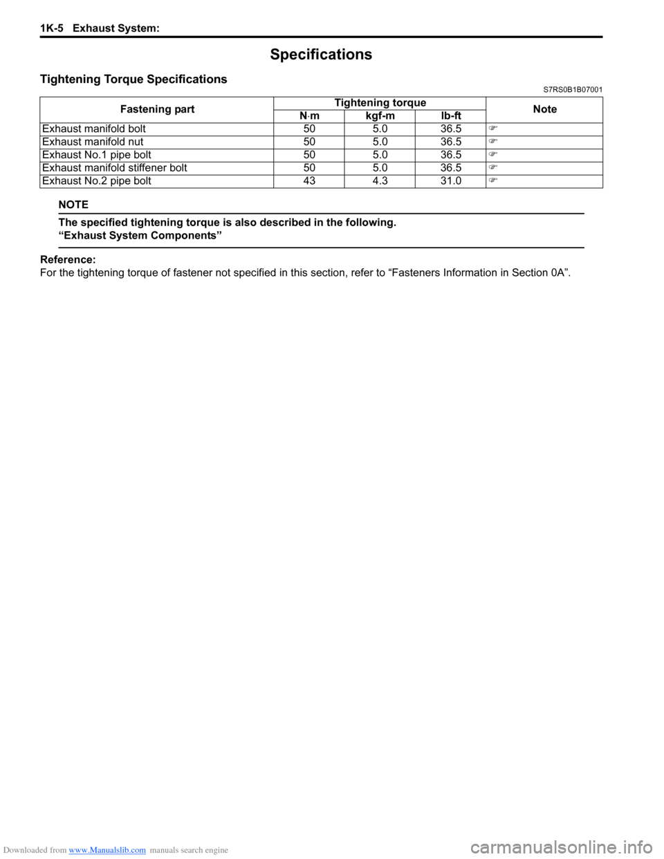
Tightening Torque SpecificationsS7RS0B1B07001
NOTE
The specified tightening torque is also described in the following.
“Exhaust System Components”
Reference:
For the tightening torque of fastener not specified in this section, refer to “Fasteners Information in Section 0A”.
Fastening part
Tightening torque
Note
N ⋅mkgf-mlb-ft
Exhaust manifold bolt 505.0 36.5 �)
Exhaust manifold nut 505.0 36.5 �)
Exhaust No.1 pipe bolt 505.0 36.5 �)
Exhaust manifold stiffener bolt 505.0 36.5 �)
Exhaust No.2 pipe bolt 434.3 31.0 �)