2008 SUZUKI SWIFT brake line
[x] Cancel search: brake linePage 675 of 1496

Downloaded from www.Manualslib.com manuals search engine Automatic Transmission/Transaxle: 5A-31
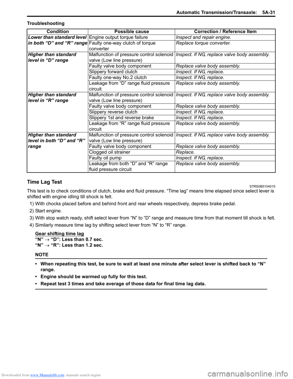
Troubleshooting
Time Lag TestS7RS0B5104015
This test is to check conditions of clutch, brake and fluid pressure. “Time lag” means time elapsed since select lever is
shifted with engine idling till shock is felt.
1) With chocks placed before and behind front and rear wheels respectively, depress brake pedal.
2) Start engine.
3) With stop watch ready, shift select lever from “N” to “D” range an d measure time from that moment till shock is felt.
4) Similarly measure time lag by shifting select lever from “N” to “R” range.
Gear shifting time lag
“N” → “D”: Less than 0.7 sec.
“N” → “R”: Less than 1.2 sec.
NOTE
• When repeating this test, be sure to wait at least one minute after select lever is shifted back to “N”
range.
• Engine should be warmed up fully for this test.
• Repeat test 3 times and take average of those data for final time lag data.
Condition Possible cause Correction / Reference Item
Lower than standard level
in both “D” and “R” range Engine output torque failure
Inspect and repair engine.
Faulty one-way clutch of torque
converter Replace torque converter.
Higher than standard
level in “D” range Malfunction of pressure control solenoid
valve (Low line pressure) Inspect. If NG, replace valve body assembly.
Faulty valve body component Replace valve body assembly.
Slippery forward clutch Inspect. If NG, replace.
Faulty one-way No.2 clutch Inspect. If NG, replace.
Leakage from “D” range fluid pressure
circuit Replace valve body assembly.
Higher than standard
level in “R” range Malfunction of pressure control solenoid
valve (Low line pressure) Inspect. If NG, replace valve body assembly.
Faulty valve body component Replace valve body assembly.
Slippery reverse clutch Inspect. If NG, replace.
Slippery 1st and reverse brake Inspect. If NG, replace.
Leakage from “R” range fluid pressure
circuit Replace valve body assembly.
Higher than standard
level in both “D” and “R”
range Malfunction of pressure control solenoid
valve (Low line pressure)
Inspect. If NG, replace valve body assembly.
Faulty valve body component Replace valve body assembly.
Clogged oil strainer Replace.
Faulty oil pump Inspect. If NG, replace.
Leakage from both “D” and “R” range
fluid pressure circuit Replace valve body assembly.
Page 676 of 1496

Downloaded from www.Manualslib.com manuals search engine 5A-32 Automatic Transmission/Transaxle:
Troubleshooting
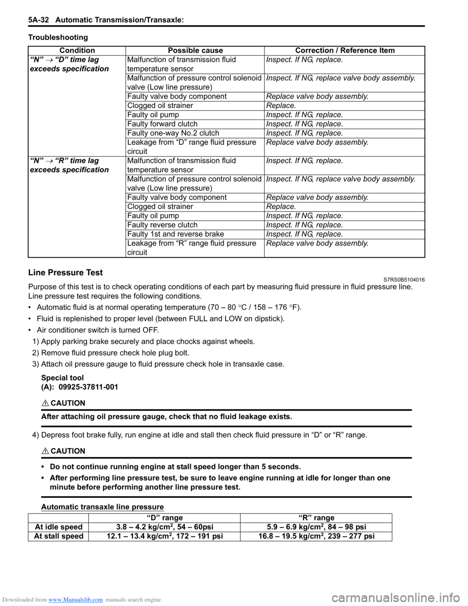
Line Pressure TestS7RS0B5104016
Purpose of this test is to check operat ing conditions of each part by measuring fluid pressure in fluid pressure line.
Line pressure test requires the following conditions.
• Automatic fluid is at normal operating temperature (70 – 80 °C / 158 – 176 °F).
• Fluid is replenished to proper level (between FULL and LOW on dipstick).
• Air conditioner switch is turned OFF.
1) Apply parking brake securely and place chocks against wheels.
2) Remove fluid pressure check hole plug bolt.
3) Attach oil pressure gauge to fluid pr essure check hole in transaxle case.
Special tool
(A): 09925-37811-001
CAUTION!
After attaching oil pressure gauge, check that no fluid leakage exists.
4) Depress foot brake fully, run engine at idle and stall then check fluid pressure in “D” or “R” range.
CAUTION!
• Do not continue running engine at stall speed longer than 5 seconds.
• After performing line pressure test, be sure to leave engine running at idle for longer than one minute before performing another line pressure test.
Automatic transaxle line pressure
Condition Possible cause Correction / Reference Item
“N”
→ “D” time lag
exceeds specification Malfunction of transmission fluid
temperature sensor Inspect. If NG, replace.
Malfunction of pressure control solenoid
valve (Low line pressure) Inspect. If NG, replace valve body assembly.
Faulty valve body component Replace valve body assembly.
Clogged oil strainer Replace.
Faulty oil pump Inspect. If NG, replace.
Faulty forward clutch Inspect. If NG, replace.
Faulty one-way No.2 clutch Inspect. If NG, replace.
Leakage from “D” range fluid pressure
circuit Replace valve body assembly.
“N”
→ “R” time lag
exceeds specification Malfunction of transmission fluid
temperature sensor Inspect. If NG, replace.
Malfunction of pressure control solenoid
valve (Low line pressure) Inspect. If NG, replace valve body assembly.
Faulty valve body component Replace valve body assembly.
Clogged oil strainer Replace.
Faulty oil pump Inspect. If NG, replace.
Faulty reverse clutch Inspect. If NG, replace.
Faulty 1st and reverse brake Inspect. If NG, replace.
Leakage from “R” range fluid pressure
circuit Replace valve body assembly.
“D” range
“R” range
At idle speed 3.8 – 4.2 kg/cm2, 54 – 60psi 5.9 – 6.9 kg/cm2, 84 – 98 psi
At stall speed 12.1 – 13.4 kg/cm2, 172 – 191 psi 16.8 – 19.5 kg/cm2, 239 – 277 psi
Page 677 of 1496

Downloaded from www.Manualslib.com manuals search engine Automatic Transmission/Transaxle: 5A-33
Troubleshooting
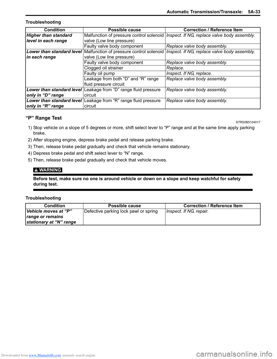
“P” Range TestS7RS0B5104017
1) Stop vehicle on a slope of 5 degrees or more, shift select lever to “P” range and at the same time apply parking brake.
2) After stopping engine, depress brake pedal and release parking brake.
3) Then, release brake pedal gradually and check that vehicle remains stationary.
4) Depress brake pedal and shift select lever to “N” range.
5) Then, release brake pedal gradually and check that vehicle moves.
WARNING!
Before test, make sure no one is around vehicle or down on a slope and keep watchful for safety
during test.
Troubleshooting Condition Possible cause Correction / Reference Item
Higher than standard
level in each range Malfunction of pressure control solenoid
valve (Low line pressure) Inspect. If NG, replace valve body assembly.
Faulty valve body component Replace valve body assembly.
Lower than standard level
in each range Malfunction of pressure control solenoid
valve (Low line pressure) Inspect. If NG, replace valve body assembly.
Faulty valve body component Replace valve body assembly.
Clogged oil strainer Replace.
Faulty oil pump Inspect. If NG, replace.
Leakage from both “D” and “R” range
fluid pressure circuit Replace valve body assembly.
Lower than standard level
only in “D” range Leakage from “D” range fluid pressure
circuit Replace valve body assembly.
Lower than standard level
only in “R” range Leakage from “R” range fluid pressure
circuit Replace valve body assembly.
Condition
Possible cause Correction / Reference Item
Vehicle moves at “P”
range or remains
stationary at “N” range Defective parking lock pawl or spring
Inspect. If NG, repair.
Page 681 of 1496

Downloaded from www.Manualslib.com manuals search engine Automatic Transmission/Transaxle: 5A-37
Non operate TCC (lock-
up) systemTCC pressure control solenoid valve
circuit faulty Inspect circuit for open, short and intermittent.
If NG, repair.
Shift solenoid valve-A and/or-B circuit
faulty Inspect circuit for open, short and intermittent.
If NG, repair.
Pressure control solenoid valve circuit
faulty Inspect circuit for open, short and intermittent.
If NG, repair.
Output shaft speed sensor circuit faulty Inspect circuit for open, short and intermittent.
If NG, repair.
Input shaft speed sensor circuit faulty Inspect circuit for open, short and intermittent.
If NG, repair.
Transmission range sensor circuit faulty Inspect circuit for open, short and intermittent.
If NG, repair.
Transmission fluid temperature sensor
circuit faulty Inspect circuit for open, short and intermittent.
If NG, repair.
CAN communication circuit faulty Inspect circuit for open, short and intermittent.
If NG, repair.
Throttle position sensor circuit faulty Inspect circuit for open, short and intermittent
referring to “Electric Throttle Body Assembly
On-Vehicle Inspection in Section 1C”. If NG,
repair.
Engine coolant temperature sensor
circuit faulty Inspect circuit for open, short and intermittent
referring to “DTC P0117: Engine Coolant
Temperature Circuit Low
in Section 1A” and/or
“DTC P0118: Engine Coolant Temperature
Circuit High in Section 1A”. If NG, repair.
Brake light switch circuit faulty Refer to “No Lock-Up Occurs”.
TCM Substitute a known-good TCM and recheck.
ECM Substitute a known-good ECM and recheck.
Higher or lower stall
speed Pressure control solenoid valve circuit
faulty Inspect circuit for open, short and intermittent.
If NG, repair.
TCM Substitute a known-good TCM and recheck.
Excessive “N”
→ “D” or
“N”
→ “R” time lag Pressure control solenoid valve circuit
faulty Inspect circuit for open, short and intermittent.
If NG, repair.
Transmission fluid temperature sensor
circuit faulty Inspect circuit for open, short and intermittent.
If NG, repair.
TCM Substitute a known-good TCM and recheck.
Higher or lower line
pressure Pressure control solenoid valve circuit
faulty Inspect circuit for open, short and intermittent.
If NG, repair.
TCM Substitute a known-good TCM and recheck.
Condition Possible cause Correction / Reference Item
Page 853 of 1496

Downloaded from www.Manualslib.com manuals search engine Clutch: 5C-1
Transmission / Transaxle
Clutch
General Description
Clutch ConstructionS7RS0B5301001
The clutch is a diaphragm spring clutch of a dry single disc type. The diaphragm spring is of a tapering-finger type,
which is a solid ring in the outer diameter part, with a series of tapered fingers pointing inward.
The disc, carrying four torsional coil springs, is positione d on the transaxle input shaft with an involute spline fit.
The clutch cover is secured to the flywheel, and carries the diaphragm spring in such a way that the peripheral edge
part of the spring pushes on the pressure plate against the flywheel (with the disc in between), when the clutch release
bearing is held back. This is the engaged condition of the clutch.
Depressing the clutch pedal c auses the release bearing to advance and pushes on the tips of the tapered fingers of
the diaphragm spring. When this happens, the diaphragm sp ring pulls the pressure plate away from the flywheel,
thereby interrupting the flow of drive from flywheel through clutch disc to transaxle input shaft. Clutch fluid is supplied
from brake fluid reservoir. Clutch fluid level can be checked by brake fluid level of brake fluid reservoir.
[A]: For petrol engine model2. Flywheel5. Clutch cover 8. Input shaft bearing
[B]: For diesel engine model 3. Clutch disc6. Diaphragm spring 9. Input shaft
1. Crankshaft 4. Pressure plate7. Release bearing 10. Release shaft
I4RS0A530001-01
Page 1435 of 1496

Downloaded from www.Manualslib.com manuals search engine Body Electrical Control System: 10B-32
BCM connector “E46”L01-8
“3” position switch
(A/T model) *0 – 1 V
↑↓
10 – 14 V Refer to “Reference waveform No. 2: ”
0 V Ignition switch is at ON positi
on and A/T select lever is at
“2” or “3” position
L01-9 — — —
L01-10 Driver side door lock actuator
control (Unlock) (if equipped) 10 – 14 V Unlock signal is output for driver side door lock actuator.
0 V Unlock signal is not output for driver side door lock
actuator.
L01-11 Rear end door opener
actuator control 0 V Rear end door opener actuator is not in operation
10 – 14 V Rear end door opener actuator is in operation
L01-12 Manual door lock switch
(Lock) 10 – 14 V
Manual door lock switch is at any position other than lock
position
0 V Manual door lock swit ch is at lock position
L01-13 — — —
L01-14 Driver side seat belt switch *0 – 3 V
↑↓
10 – 14 V Refer to “Reference waveform No. 3: ”
0 V Ignition switch is at ON position and driver side seat belt
is unfastened
L01-15 Door switch (other than driver
side door and rear end door) 10 – 14 V
Rear right and left side door and passenger side door are
closed
0 V Any one of the door is opened (except driver side door
and rear end door)
L01-16 Driver side door key cylinder switch (Lock) 10 – 14 V
Driver side door key cylinder switch is at any position
other than lock position
0 V Driver side door key cylinder switch is at lock position
L01-17 Driver side door key cylinder
switch (Unlock) 10 – 14 V
Driver side door key cylinder switch is at any position
other than unlock position
0 V Driver side door key cylinder switch is at unlock position
L01-18 — — —
Terminal Circuit Normal voltage Condition
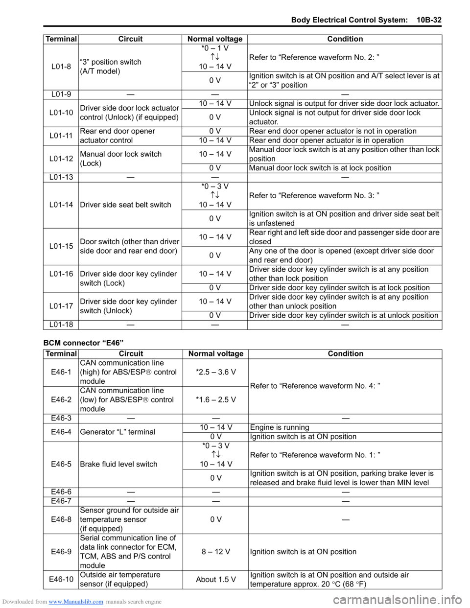
Terminal
CircuitNormal voltage Condition
E46-1 CAN communication line
(high) for ABS/ESP
® control
module *2.5 – 3.6 V
Refer to “Reference waveform No. 4: ”
E46-2 CAN communication line
(low) for ABS/ESP
® control
module *1.6 – 2.5 V
E46-3 — — —
E46-4 Generator “L” terminal 10 – 14 V Engine is running
0 V Ignition switch is at ON position
E46-5 Brake fluid level switch *0 – 3 V
↑↓
10 – 14 V Refer to “Reference waveform No. 1: ”
0 V Ignition switch is at ON position, parking brake lever is
released and brake fluid level is lower than MIN level
E46-6 — — —
E46-7 — — —
E46-8 Sensor ground for outside air
temperature sensor
(if equipped) 0 V
—
E46-9 Serial communication line of
data link connector for ECM,
TCM, ABS and
P/S control
module 8 – 12 V Ignition switch is at ON position
E46-10 Outside air temperature
sensor (if equipped) About 1.5 VIgnition switch is at ON position and outside air
temperature approx. 20
°C (68 °F)