2008 SUZUKI SWIFT high tension
[x] Cancel search: high tensionPage 1094 of 1496
Downloaded from www.Manualslib.com manuals search engine 8B-56 Air Bag System:
NOTE
Upon completion of inspection and repair work, perform the following items.
• Reconnect all air bag system components and ensure all components are properly mounted.
• Clear DTCs referring to “DTC Clearance”, if any.
• Repeat “Air Bag Diagnostic System Check” to confirm that the trouble has been corrected.
DTC B1051 / B1055: Driver / Passenger Pretensioner Initiator Circuit Resistance HighS7RS0B8204026
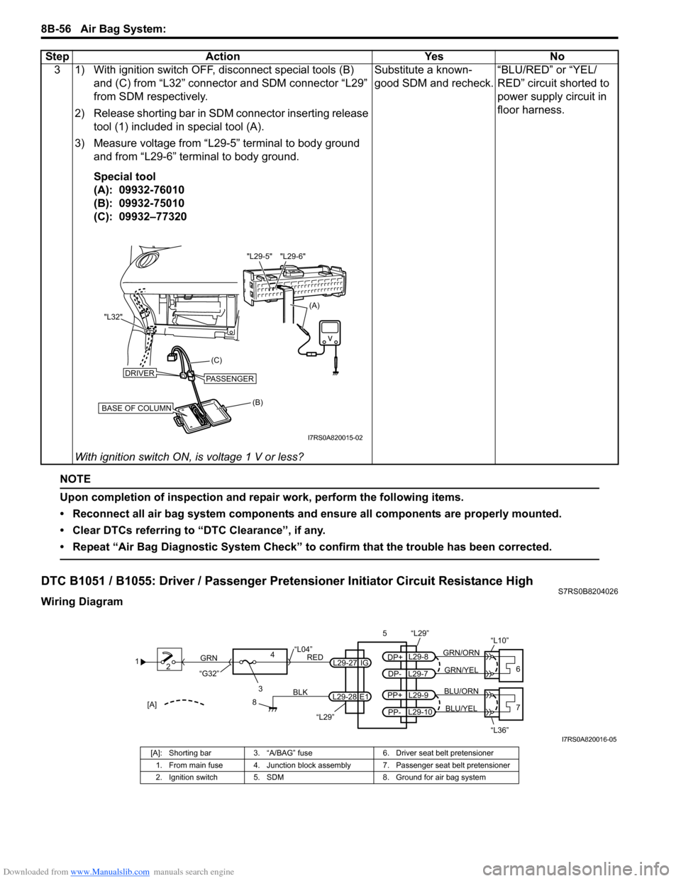
Wiring Diagram3 1) With ignition switch OFF, disconnect special tools (B)
and (C) from “L32” connector and SDM connector “L29”
from SDM respectively.
2) Release shorting bar in SDM connector inserting release tool (1) included in special tool (A).
3) Measure voltage from “L29-5” terminal to body ground and from “L29-6” terminal to body ground.
Special tool
(A): 09932-76010
(B): 09932-75010
(C): 09932–77320
With ignition switch ON, is voltage 1 V or less? Substitute a known-
good SDM and recheck.
“BLU/RED” or “YEL/
RED” circuit shorted to
power supply circuit in
floor harness.
Step Action Yes No
(B)
(C)
"L32"
BASE OF COLUMN
DRIVERPASSENGER
(A)
"L29-6"
"L29-5"
I7RS0A820015-02
1
2
3
GRN
RED
8
BLK
L29-27
L29-28 IG
E1
4
“L29”
“L04”
“G32”
“L29”
L29-8
DP+
L29-7
DP-GRN/YEL
GRN/ORN
56
“L10”
L29-9
PP+
L29-10
PP-BLU/YEL
BLU/ORN7
“L36”[A]
I7RS0A820016-05
[A]: Shorting bar 3. “A/BAG” fuse 6. Driver seat belt pretensioner
1. From main fuse 4. Junction block assembly 7. Passenger seat belt pretensioner
2. Ignition switch 5. SDM 8. Ground for air bag system
Page 1096 of 1496
Downloaded from www.Manualslib.com manuals search engine 8B-58 Air Bag System:
NOTE
Upon completion of inspection and repair work, perform the following items.
• Reconnect all air bag system components and ensure all components are properly mounted.
• Clear DTCs referring to “DTC Clearance”, if any.
• Repeat “Air Bag Diagnostic System Check” to confirm that the trouble has been corrected.
DTC B1052 / B1056: Driver / Passenger Pretensioner Initiator Circuit Resistance LowS7RS0B8204027
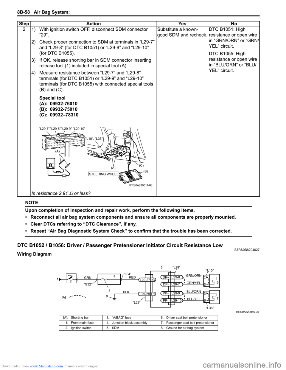
Wiring Diagram2 1) With ignition switch OFF, disconnect SDM connector
“29”.
2) Check proper connection to SDM at terminals in “L29-7” and “L29-8” (for DTC B1051) or “L29-9” and “L29-10”
(for DTC B1055).
3) If OK, release shorting bar in SDM connector inserting
release tool (1) included in special tool (A).
4) Measure resistance between “L29-7” and “L29-8” terminals (for DTC B1051) or “L29-9” and “L29-10”
terminals (for DTC B1055) with connected special tools
(B) and (C).
Special tool
(A): 09932-76010
(B): 09932-75010
(C): 09932–78310
Is resistance 2.91
Ω or less? Substitute a known-
good SDM and recheck.
DTC B1051: High
resistance or open wire
in “GRN/ORN” or “GRN/
YEL” circuit.
DTC B1055: High
resistance or open wire
in “BLU/ORN” or “BLU/
YEL” circuit.
Step Action Yes No
(A)
"L29-8" "L29-9" "L29-10"
"L29-7"
STEERING WHEEL(B)
(C)
(A)
"L10", "L36"
I7RS0A820017-03
1
2
3
GRN
RED
8
BLK
L29-27
L29-28 IG
E1
4
“L29”
“L04”
“G32”
“L29”
L29-8
DP+
L29-7
DP-GRN/YEL
GRN/ORN
56
“L10”
L29-9
PP+
L29-10
PP-BLU/YEL
BLU/ORN7
“L36”[A]
I7RS0A820016-05
[A]: Shorting bar 3. “A/BAG” fuse 6. Driver seat belt pretensioner
1. From main fuse 4. Junction block assembly 7. Passenger seat belt pretensioner
2. Ignition switch 5. SDM 8. Ground for air bag system
Page 1133 of 1496
Downloaded from www.Manualslib.com manuals search engine Air Bag System: 8B-95
Inspection of Intermittent and Poor
Connections
S7RS0B8204048
Most intermittents are caused by faulty electrical
connections or wiring. When a check for proper
connection is requested in a diagnostic flow, perform
careful check of suspect circuits.
If any abnormality is found, repair or replace as a wire
harness assembly.
• Poor mating of connector halves, or terminals not fully seated in the connector body (backed out).
• Dirt or corrosion on the terminals. The terminals must be clean and free of any foreign material which could
impede proper terminal contact.
However, cleaning the terminal with a sand paper or
the like is prohibited.
• Damaged connector body, exposing the terminals to moisture and dirt, as well as not maintaining proper
terminal orientation with the component or mating
connector.
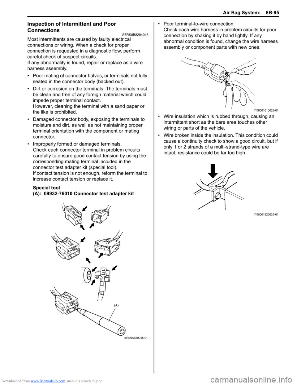
• Improperly formed or damaged terminals. Check each connector terminal in problem circuits
carefully to ensure good contact tension by using the
corresponding mating terminal included in the
connector test adapter kit (special tool).
If contact tension is not e nough, reform the terminal to
increase contact tension or replace it.
Special tool
(A): 09932-76010 Connector test adapter kit • Poor terminal-to-wire connection.
Check each wire harness in problem circuits for poor
connection by shaking it by hand lightly. If any
abnormal condition is found, change the wire harness
assembly or component parts with new ones.
• Wire insulation which is rubbed through, causing an intermittent short as the bare area touches other
wiring or parts of the vehicle.
• Wire broken inside the insulation. This condition could cause a continuity check to show a good circuit, but if
only 1 or 2 strands of a multi-strand-type wire are
intact, resistance could be far too high.
(A)
I4RS0A820045-01
IYSQ01010028-01
IYSQ01820025-01
Page 1152 of 1496
Downloaded from www.Manualslib.com manuals search engine 8B-114 Air Bag System:
Deployment / Activation Outside of Vehicle
When you intend to return the vehicle to service, deploy
the air bag (inflator) module(s) or activate seat belt
pretensioner(s) outside of the vehicle.1) Turn ignition switch to LOCK position and remove key.
2) Wear safety glasses during this deployment / activation procedure.
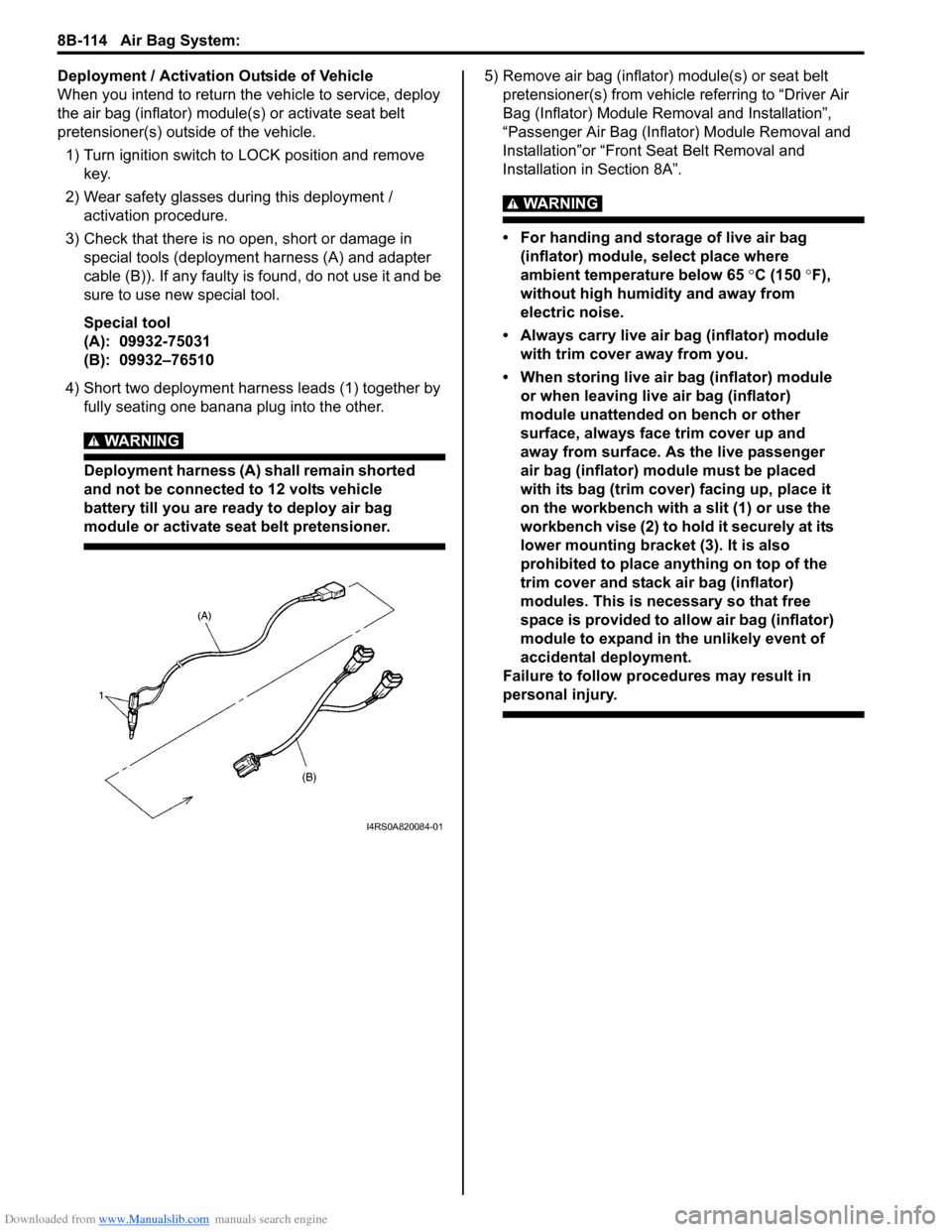
3) Check that there is no open, short or damage in special tools (deployment harness (A) and adapter
cable (B)). If any faulty is found, do not use it and be
sure to use new special tool.
Special tool
(A): 09932-75031
(B): 09932–76510
4) Short two deployment harness leads (1) together by fully seating one banana plug into the other.
WARNING!
Deployment harness (A) shall remain shorted
and not be connected to 12 volts vehicle
battery till you are ready to deploy air bag
module or activate seat belt pretensioner.
5) Remove air bag (inflator) module(s) or seat belt pretensioner(s) from vehicle referring to “Driver Air
Bag (Inflator) Module Re moval and Installation”,
“Passenger Air Bag (Inflator) Module Removal and
Installation”or “Front Seat Belt Removal and
Installation in Section 8A”.
WARNING!
• For handing and storage of live air bag (inflator) module, select place where
ambient temperature below 65 °C (150 °F),
without high humidity and away from
electric noise.
• Always carry live air bag (inflator) module with trim cover away from you.
• When storing live air bag (inflator) module or when leaving live air bag (inflator)
module unattended on bench or other
surface, always face trim cover up and
away from surface. As the live passenger
air bag (inflator) module must be placed
with its bag (trim cover) facing up, place it
on the workbench with a slit (1) or use the
workbench vise (2) to hold it securely at its
lower mounting bracket (3). It is also
prohibited to place anything on top of the
trim cover and stack air bag (inflator)
modules. This is necessary so that free
space is provided to allow air bag (inflator)
module to expand in the unlikely event of
accidental deployment.
Failure to follow procedures may result in
personal injury.
I4RS0A820084-01
Page 1153 of 1496
Downloaded from www.Manualslib.com manuals search engine Air Bag System: 8B-115
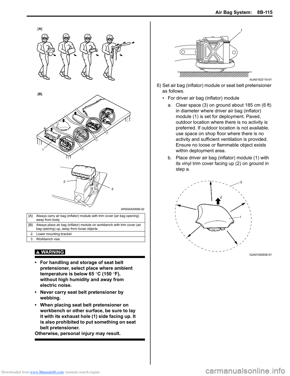
WARNING!
• For handling and storage of seat belt pretensioner, select place where ambient
temperature is below 65 °C (150 °F),
without high humidity and away from
electric noise.
• Never carry seat belt pretensioner by webbing.
• When placing seat belt pretensioner on workbench or other surface, be sure to lay
it with its exhaust hole (1) side facing up. It
is also prohibited to put something on seat
belt pretensioner.
Otherwise, personal injury may result.
6) Set air bag (inflator) module or seat belt pretensioner
as follows.
• For driver air bag (inflator) module
a. Clear space (3) on ground about 185 cm (6 ft) in diameter where driver air bag (inflator)
module (1) is set for deployment. Paved,
outdoor location where there is no activity is
preferred. If outdoor location is not available,
use space on shop floor where there is no
activity and sufficient ventilation is provided.
Ensure no loose or flammable object exists
within deployment area.
b. Place driver air bag (inflator) module (1) with its vinyl trim cover facing up (2) on ground in
step a.
[A]: Always carry air bag (inflator) module with trim cover (air bag opening) away from body.
[B]: Always place air bag (inflator) module on workbench with trim cover (air bag opening) up, away from loose objects.
2. Lower mounting bracket
3. Workbench vise
1
2
3
[A]
[B]
I4RS0A820086-02
1
I4JA01822118-01
I3JA01820036-01
Page 1195 of 1496
Downloaded from www.Manualslib.com manuals search engine Wiring Systems: 9A-24
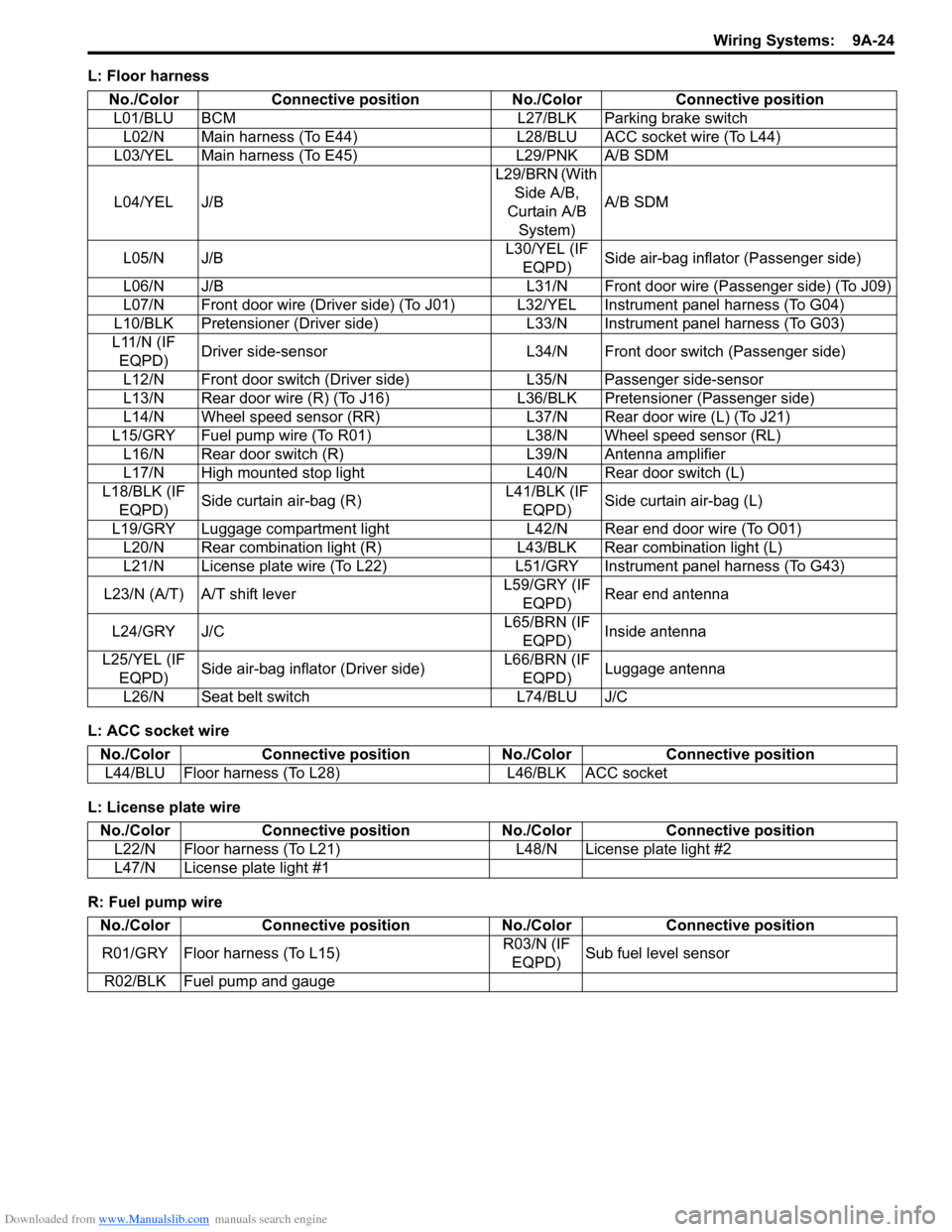
L: Floor harness
L: ACC socket wire
L: License plate wire
R: Fuel pump wireNo./Color Connective position No./Color Connective position
L01/BLU BCM L27/BLK Parking brake switch L02/N Main harness (To E44) L28/BLU ACC socket wire (To L44)
L03/YEL Main harness (To E45) L29/PNK A/B SDM
L04/YEL J/B L29/BRN (With
Side A/B,
Curtain A/B System) A/B SDM
L05/N J/B L30/YEL (IF
EQPD) Side air-bag inflator (Passenger side)
L06/N J/B L31/N Front door wire (Passenger side) (To J09)
L07/N Front door wire (Driver side) (To J01) L32/YEL Instrument panel harness (To G04)
L10/BLK Pretensioner (Driver side) L33/N Instrument panel harness (To G03)
L11/N (IF EQPD) Driver side-sensor L34/N Front door switch (Passenger side)
L12/N Front door switch (Driver side) L35/N Passenger side-sensor
L13/N Rear door wire (R) (To J16) L 36/BLK Pretensioner (Passenger side)
L14/N Wheel speed sensor (RR) L37/N Rear door wire (L) (To J21)
L15/GRY Fuel pump wire (To R01) L38/N Wheel speed sensor (RL)
L16/N Rear door switch (R) L39/N Antenna amplifier
L17/N High mounted stop light L40/N Rear door switch (L)
L18/BLK (IF EQPD) Side curtain air-bag (R) L41/BLK (IF
EQPD) Side curtain air-bag (L)
L19/GRY Luggage compartment light L42/N Rear end door wire (To O01) L20/N Rear combination light (R) L43/BLK Rear combination light (L)
L21/N License plate wire (To L22) L51/ GRY Instrument panel harness (To G43)
L23/N (A/T) A/T shift lever L59/GRY (IF
EQPD) Rear end antenna
L24/GRY J/C L65/BRN (IF
EQPD) Inside antenna
L25/YEL (IF EQPD) Side air-bag inflator (Driver side) L66/BRN (IF
EQPD) Luggage antenna
L26/N Seat belt switch L74/BLU J/C
No./Color Connective position No./Color Connective position
L44/BLU Floor harness (To L28) L46/BLK ACC socket
No./ColorConnective position No./Color Connective position
L22/N Floor harness (To L21) L48/N License plate light #2
L47/N License plate light #1
No./Color Connective position No./Color Connective position
R01/GRY Floor harness (To L15) R03/N (IF
EQPD) Sub fuel level sensor
R02/BLK Fuel pump and gauge
Page 1197 of 1496
Downloaded from www.Manualslib.com manuals search engine Wiring Systems: 9A-26
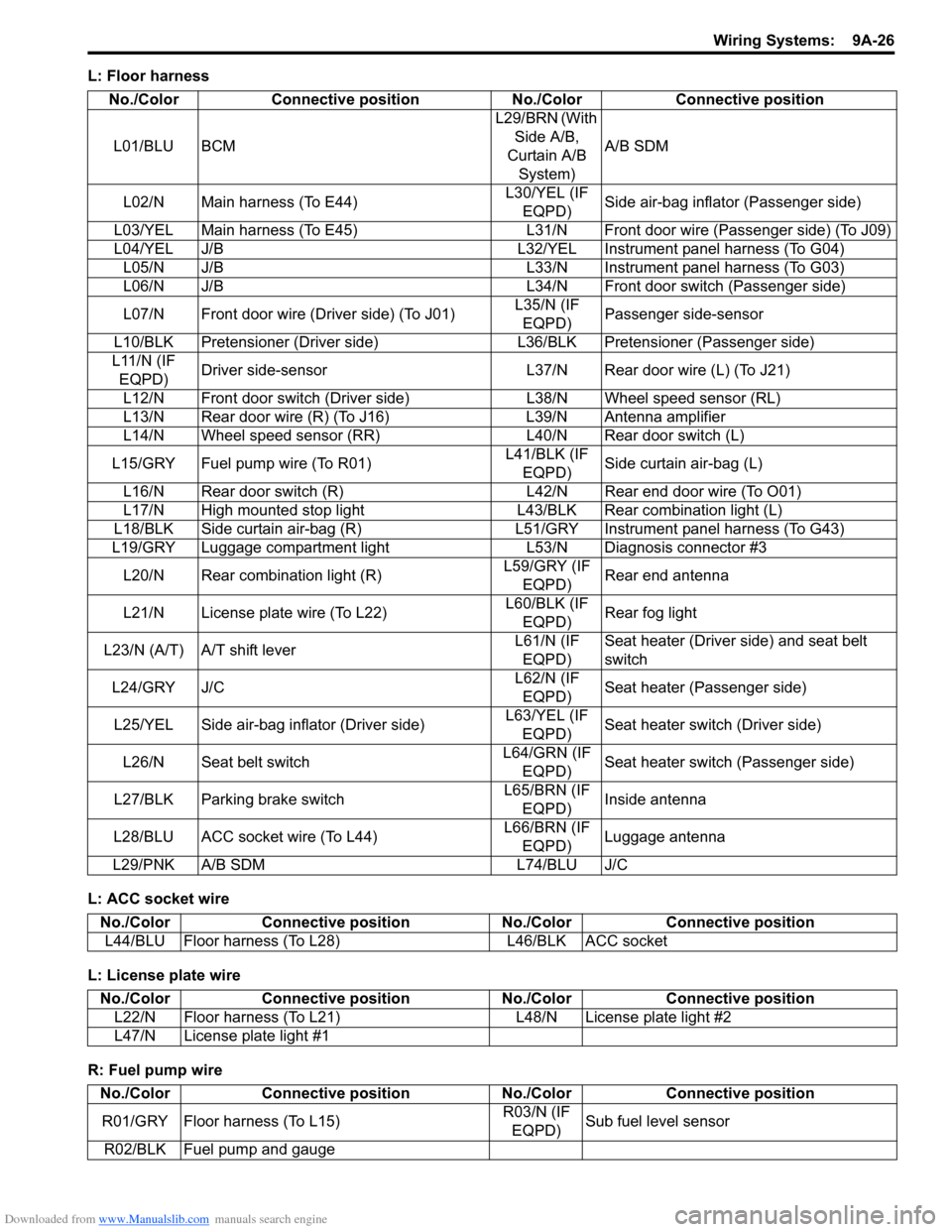
L: Floor harness
L: ACC socket wire
L: License plate wire
R: Fuel pump wireNo./Color Connective position No./Color Connective position
L01/BLU BCM L29/BRN (With
Side A/B,
Curtain A/B System) A/B SDM
L02/N Main harness (To E44) L30/YEL (IF
EQPD) Side air-bag inflator (Passenger side)
L03/YEL Main harness (To E45) L31/N Front door wire (Passenger side) (To J09)
L04/YEL J/B L32/YEL Instrument panel harness (To G04) L05/N J/B L33/N Instrument panel harness (To G03)
L06/N J/B L34/N Front door switch (Passenger side)
L07/N Front door wire (Driver side) (To J01) L35/N (IF
EQPD) Passenger side-sensor
L10/BLK Pretensioner (Driver side) L36/ BLK Pretensioner (Passenger side)
L11/N (IF EQPD) Driver side-sensor L37/N Rear door wire (L) (To J21)
L12/N Front door switch (Driver side) L38/N Wheel speed sensor (RL)
L13/N Rear door wire (R) (To J16) L39/N Antenna amplifier
L14/N Wheel speed sensor (RR) L40/N Rear door switch (L)
L15/GRY Fuel pump wire (To R01) L41/BLK (IF
EQPD) Side curtain air-bag (L)
L16/N Rear door switch (R) L42/N Rear end door wire (To O01)
L17/N High mounted stop light L43/BLK Rear combination light (L)
L18/BLK Side curtain air-bag (R) L51/GRY Instrument panel harness (To G43)
L19/GRY Luggage compartment light L53/N Diagnosis connector #3
L20/N Rear combin ation light (R) L59/GRY (IF
EQPD) Rear end antenna
L21/N License plate wire (To L22) L60/BLK (IF
EQPD) Rear fog light
L23/N (A/T) A/T shift lever L61/N (IF
EQPD) Seat heater (Driver side) and seat belt
switch
L24/GRY J/C L62/N (IF
EQPD) Seat heater (Passenger side)
L25/YEL Side air-bag inflator (Driver side) L63/YEL (IF
EQPD) Seat heater switch (Driver side)
L26/N Seat belt switch L64/GRN (IF
EQPD) Seat heater switch (Passenger side)
L27/BLK Parking brake switch L65/BRN (IF
EQPD) Inside antenna
L28/BLU ACC socket wire (To L44) L66/BRN (IF
EQPD) Luggage antenna
L29/PNK A/B SDM L74/BLU J/C
No./Color Connective position No./Color Connective position
L44/BLU Floor harness (To L28) L46/BLK ACC socket
No./ColorConnective position No./Color Connective position
L22/N Floor harness (To L21) L48/N License plate light #2
L47/N License plate light #1
No./Color Connective position No./Color Connective position
R01/GRY Floor harness (To L15) R03/N (IF
EQPD) Sub fuel level sensor
R02/BLK Fuel pump and gauge
Page 1199 of 1496
Downloaded from www.Manualslib.com manuals search engine Wiring Systems: 9A-28
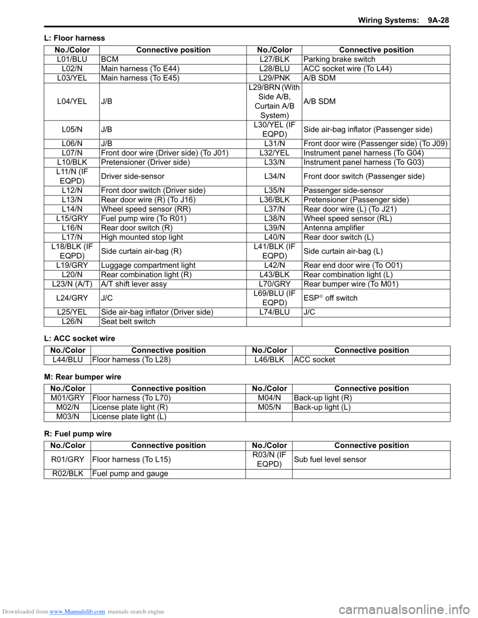
L: Floor harness
L: ACC socket wire
M: Rear bumper wire
R: Fuel pump wireNo./Color Connective position No./Color Connective position
L01/BLU BCM L27/BLK Parking brake switch L02/N Main harness (To E44) L28/BLU ACC socket wire (To L44)
L03/YEL Main harness (To E45) L29/PNK A/B SDM
L04/YEL J/B L29/BRN (With
Side A/B,
Curtain A/B System) A/B SDM
L05/N J/B L30/YEL (IF
EQPD) Side air-bag inflator (Passenger side)
L06/N J/B L31/N Front door wire (Passenger side) (To J09)
L07/N Front door wire (Driver side) (To J01) L32/YEL Instrument panel harness (To G04)
L10/BLK Pretensioner (Driver side) L33/N Instrument panel harness (To G03)
L11/N (IF EQPD) Driver side-sensor L34/N Front door switch (Passenger side)
L12/N Front door switch (Driver side) L35/N Passenger side-sensor
L13/N Rear door wire (R) (To J16) L 36/BLK Pretensioner (Passenger side)
L14/N Wheel speed sensor (RR) L37/N Rear door wire (L) (To J21)
L15/GRY Fuel pump wire (To R01) L38/N Wheel speed sensor (RL)
L16/N Rear door switch (R) L39/N Antenna amplifier
L17/N High mounted stop light L40/N Rear door switch (L)
L18/BLK (IF EQPD) Side curtain air-bag (R) L41/BLK (IF
EQPD) Side curtain air-bag (L)
L19/GRY Luggage compartment light L42/N Rear end door wire (To O01) L20/N Rear combination light (R) L43/BLK Rear combination light (L)
L23/N (A/T) A/T shift lever assy L70/GRY Rear bumper wire (To M01)
L24/GRY J/C L69/BLU (IF
EQPD) ESP
® off switch
L25/YEL Side air-bag inflator (Driver side) L74/BLU J/C L26/N Seat belt switch
No./Color Connective position No./Color Connective position
L44/BLU Floor harness (To L28) L46/BLK ACC socket
No./ColorConnective position No./Color Connective position
M01/GRY Floor harness (To L70) M04/N Back-up light (R)
M02/N License plate light (R) M05/N Back-up light (L)
M03/N License plate light (L)
No./Color Connective position No./Color Connective position
R01/GRY Floor harness (To L15) R03/N (IF
EQPD) Sub fuel level sensor
R02/BLK Fuel pump and gauge