2008 SUZUKI SWIFT clutch switch
[x] Cancel search: clutch switchPage 831 of 1496

Downloaded from www.Manualslib.com manuals search engine Manual Transmission/Transaxle: 5B-17
5) Remove gear shift locating bolts (1) with washers,
then take out locating springs and steel balls.
6) Remove back up light switch (2).
7) Remove reverse shaft bolt (2) with washer.
8) Remove case bolts (1) from outside and another bolts from clutch housing side.
9) Tapping left case flanges with plastic hammer, remove left case (3).
10) Pull out reverse gear shaft (1) with washer (2), then take off reverse idler gear (3).
11) Remove reverse gear shift lever bolts (4) and reverse gear shift lever (5).
12) Pull out 5th & reverse gear shift guide shaft (6) together with 5th & reverse gear shift shaft (7). 13) Tapping input shaft end with plastic hammer, push it
out as assembly from case a little, then take out
input shaft assembly (1), countershaft assembly (2),
high speed gear shift shaft (3) and low speed gear
shift shaft (4) all at once.
14) Remove countershaft left bearing outer race from left case (1) using special tool.
Special tool
(A): 09913–70123
15) Remove side bearing retainer bolts.
16) Turn side bearing retainer (1) counterclockwise until it stops, and remove side bearing retainer using 2 flat
end rods (2) or the like.
17) Remove O-ring from side bearing retainer.
I2RH01520032-01
I4RS0A520032-01
I4RS0A520033-01
I2RH01520035-01
(A)
1
I4RH01520021-01
1
2
2
I4RS0A520034-01
Page 856 of 1496
Downloaded from www.Manualslib.com manuals search engine 5C-4 Clutch:
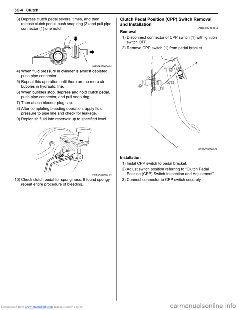
3) Depress clutch pedal several times, and then release clutch pedal, push snap ring (2) and pull pipe
connector (1) one notch.
4) When fluid pressure in cylinder is almost depleted, push pipe connector.
5) Repeat this operation until there are no more air bubbles in hydraulic line.
6) When bubbles stop, depress and hold clutch pedal, push pipe connector, and pull snap ring.
7) Then attach bleeder plug cap.
8) After completing bleeding operation, apply fluid pressure to pipe line and check for leakage.
9) Replenish fluid into reserv oir up to specified level.
10) Check clutch pedal for sponginess. If found spongy, repeat entire procedure of bleeding.Clutch Pedal Position (CPP) Switch Removal
and Installation
S7RS0B5306004
Removal
1) Disconnect connector of C PP switch (1) with ignition
switch OFF.
2) Remove CPP switch (1 ) from pedal bracket.
Installation 1) Instal CPP switch to pedal bracket.
2) Adjust switch position re ferring to “Clutch Pedal
Position (CPP) Switch Inspection and Adjustment”.
3) Connect connector to CPP switch securely.
2
1
I4RS0A530004-01
I4RS0A530023-01
1
I6RS0C530001-02
Page 857 of 1496

Downloaded from www.Manualslib.com manuals search engine Clutch: 5C-5
Clutch Pedal Position (CPP) Switch Inspection
and Adjustment
S7RS0B5306005
Inspection
Check for resistance between terminals under each
condition below. If check result is not satisfactory,
replace.
CPP switch resistance
When switch shaft is pushed (1): Continuity
When switch shaft is free (2): No continuityAdjustment
With clutch pedal depressed,
adjust switch (1) position
so that clearance between end of thread and clutch
pedal arm is within specification, and then tighten lock
nut to specified torque.
Clearance between end of thread and clutch pedal
arm
“a”: 3.5 – 4.0 mm (0.14 – 0.16 in.)
Tightening torque
CPP switch lock nut (a): 7.5 N·m (0.75 kgf-m, 5.5 lb-
ft)
Clutch Fluid Pipe and Hose ComponentsS7RS0B5306006
I5JB0A530006-01
(a)
1
“a”
I6RS0C530002-01
6
1
5
2 5
4(a)
3
I6RS0C530003-01
1. Master cylinder
: Apply grease 99000-25100 to push rod end. 5. Clamp
2. Pipe 6. Clutch reservoir hose
3. Operating cylinder : Apply grease 99000-25100 to rod tip. : 23 N
⋅m (2.3 kgf-m, 17.0 lb-ft)
4. Operating cylinder bolt
Page 865 of 1496
Downloaded from www.Manualslib.com manuals search engine Clutch: 5C-13
Clutch Release System InspectionS7RS0B5306017
Clutch Release Bearing
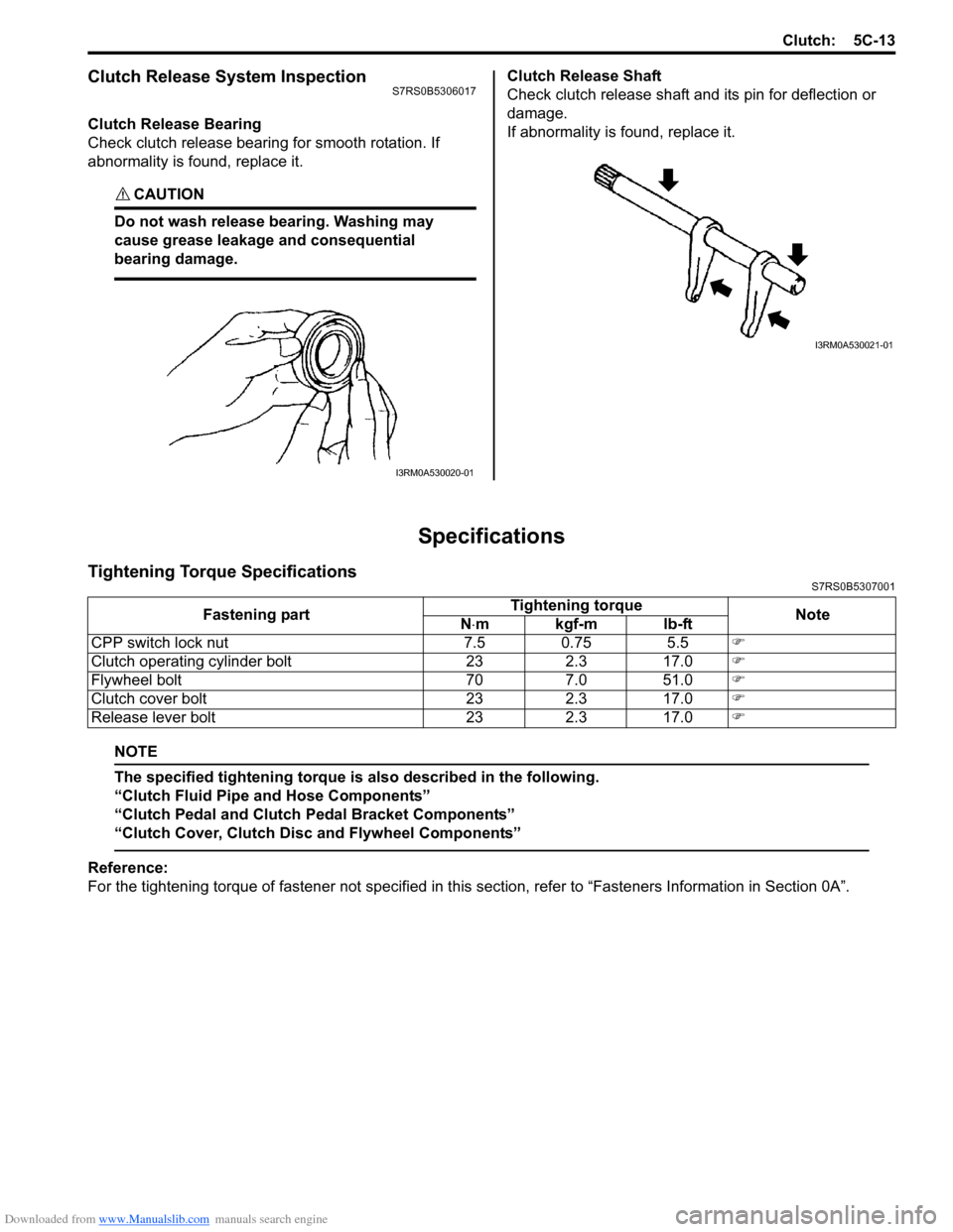
Check clutch release bearing for smooth rotation. If
abnormality is found, replace it.
CAUTION!
Do not wash release bearing. Washing may
cause grease leakage and consequential
bearing damage.
Clutch Release Shaft
Check clutch release shaft and its pin for deflection or
damage.
If abnormality is found, replace it.
Specifications
Tightening Torque SpecificationsS7RS0B5307001
NOTE
The specified tightening torque is also described in the following.
“Clutch Fluid Pipe and Hose Components”
“Clutch Pedal and Clutch Pedal Bracket Components”
“Clutch Cover, Clutch Disc and Flywheel Components”
Reference:
For the tightening torque of fastener not specified in this section, refer to “Fasteners Information in Section 0A”.
I3RM0A530020-01
I3RM0A530021-01
Fastening part Tightening torque
Note
N ⋅mkgf-mlb-ft
CPP switch lock nut 7.5 0.75 5.5 �)
Clutch operating cylinder bolt 23 2.3 17.0 �)
Flywheel bolt 70 7.0 51.0 �)
Clutch cover bolt 23 2.3 17.0 �)
Release lever bolt 23 2.3 17.0 �)
Page 933 of 1496

Downloaded from www.Manualslib.com manuals search engine Table of Contents 7- i
7
Section 7
CONTENTS
HVAC
Precautions ................................................. 7-1
Precautions............................................................. 7-1
Precautions on HVAC ........................................... 7-1
Heater and Ventilation.... ......................... 7A-1
General Description ............................................. 7A-1
Heater and Ventilation Construction ................... 7A-1
Schematic and Routing Diagram ........................ 7A-2 Heater and Ventilation Wiring Circuit Diagram .... 7A-2
Diagnostic Information and Procedures ............ 7A-3 Heater and Ventilation Symptom Diagnosis........ 7A-3
Repair Instructions .............................................. 7A-4 HVAC Unit Components ..................................... 7A-4
HVAC Unit Removal and Installation .................. 7A-4
Blower Motor Removal and Installation............... 7A-4
Blower Motor Inspection ..................................... 7A-4
Blower Motor Resistor Removal and Installation ......................................................... 7A-5
Blower Motor Resistor Inspection ....................... 7A-5
Blower Motor Relay Inspection ........................... 7A-6
HVAC Control Unit Components ......................... 7A-6
HVAC Control Unit Remova l and Installation ...... 7A-7
Blower Speed Selector In spection ...................... 7A-9
Air Intake Selector Inspec tion ............................. 7A-9
Air Intake Control Actuator Removal and Installation ......................................................... 7A-9
Air Intake Control Actuator Inspection .............. 7A-10
Center Ventilation Louver Removal and Installation ....................................................... 7A-10
Side Ventilation Louver Removal and Installation ....................................................... 7A-11
HVAC Air Filter Removal and Installation (If Equipped)........................................................ 7A-12
HVAC Air Filter Inspection (If Equipped) ........... 7A-12
Air Conditioning System... ...................... 7B-1
Manual Type ............................................................ 7B-1
Precautions........................................................... 7B-1A/C System Caution ............................................ 7B-1
Precautions on Servicing A/C System ................ 7B-1
General Description ............................................. 7B-3 Refrigerant Type Identifica tion ............................ 7B-3
Sub-Cool A/C System Description ...................... 7B-4
A/C Operation Description .................................. 7B-4 Schematic and Routing Diagram ........................7B-5
Major Components of A/C System ...................... 7B-5
A/C System Wiring Diagram ............................... 7B-6
Diagnostic Information and Procedures ............7B-7 A/C System Symptom Diagnosis ........................ 7B-7
Abnormal Noise Sympto m Diagnosis of A/C
System .............................................................. 7B-9
A/C System Performance Inspection ................ 7B-10
A/C System Inspection at ECM ......................... 7B-15
Repair Instructions ........... .................................7B-16
Operation Procedure for Re frigerant Charge .... 7B-16
Condenser Assembly On-Vehicle Inspection .... 7B-21
Condenser Assembly Removal and Installation ....................................................... 7B-21
Receiver/Dryer Removal and Installation .......... 7B-22
HVAC Unit Components ................................... 7B-23
HVAC Unit Removal and In stallation ................ 7B-24
Evaporator Inspection ....................................... 7B-24
Evaporator Thermistor (Evaporator Temperature Sensor) Removal and
Installation ....................................................... 7B-25
Evaporator Thermistor (Evaporator Temperature Sensor) Inspec tion..................... 7B-25
Expansion Valve Removal and Installation ....... 7B-26
Expansion Valve Inspection .............................. 7B-26
A/C Refrigerant Pressure Sensor and Its Circuit Inspection............................................. 7B-26
A/C Refrigerant Pressu re Sensor Removal
and Installation ................................................ 7B-26
A/C Switch Inspection ....................................... 7B-27
Compressor Relay Inspection ........................... 7B-27
Compressor Drive Belt Inspection and Adjustment ...................................................... 7B-27
Compressor Drive Belt Removal and Installation ....................................................... 7B-28
Compressor Assembly Removal and Installation ....................................................... 7B-28
Compressor Assembly Components................. 7B-29
Magnet Clutch Inspection.................................. 7B-29
Magnet Clutch Removal and Installation........... 7B-29
Relief Valve Inspection...................................... 7B-31
Relief Valve Removal and Installation............... 7B-32
Specifications .................... .................................7B-32
Tightening Torque Specifications ...................... 7B-32
Special Tools and Equipmen t ...........................7B-33
Page 952 of 1496
Downloaded from www.Manualslib.com manuals search engine 7B-4 Air Conditioning System: Manual Type
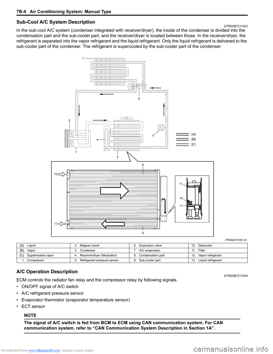
Sub-Cool A/C System DescriptionS7RS0B7211003
In the sub-cool A/C system (condenser integrated with receiver/dryer), the inside of the condenser is divided into the
condensation part and the sub-cooler part, and the receiver/dryer is located between those. In the receiver/dryer, the
refrigerant is separated into the vapor refrigerant and the liqui d refrigerant. Only the liquid refrigerant is delivered to the
sub-cooler part of the condenser. The refrigerant is supercooled by the sub-cooler part of the condenser.
A/C Operation DescriptionS7RS0B7211004
ECM controls the radiator fan relay and the compressor relay by following signals.
• ON/OFF signal of A/C switch
• A/C refrigerant pressure sensor
• Evaporator thermistor (evaporator temperature sensor)
• ECT sensor
NOTE
The signal of A/C swit ch is fed from BCM to ECM usin g CAN communication system. For CAN
communication system, refer to “CAN Communication System Description in Section 1A”.
I7RS0A721001-01
[A]: Liquid 2. Magnet clutch 6. Expansion valve10. Desiccant
[B]: Vapor 3. Condenser 7. A/C evaporator11. Filter
[C]: Superheated vapor 4. Receiver/dryer (Modulator) 8. Condensation part12. Vapor refrigerant
1. Compressor 5. Refrigerant pressure sensor 9. Sub-cooler part 13. Liquid refrigerant
Page 955 of 1496
Downloaded from www.Manualslib.com manuals search engine Air Conditioning System: Manual Type 7B-7
Diagnostic Information and Procedures
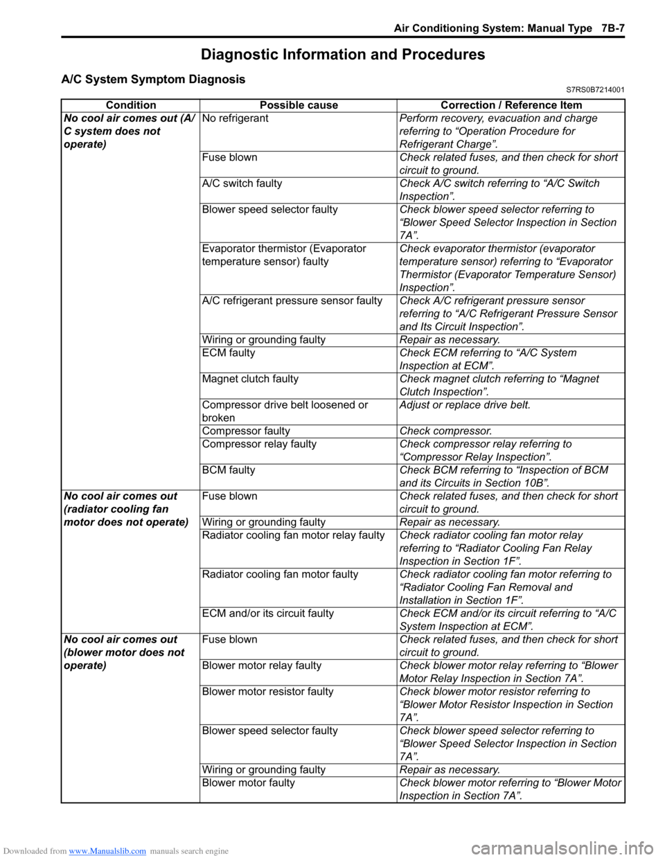
A/C System Symptom DiagnosisS7RS0B7214001
ConditionPossible cause Correction / Reference Item
No cool air comes out (A/
C system does not
operate) No refrigerant
Perform recovery, evacuation and charge
referring to “Operation Procedure for
Refrigerant Charge”.
Fuse blown Check related fuses, and then check for short
circuit to ground.
A/C switch faulty Check A/C switch referring to “A/C Switch
Inspection”.
Blower speed selector faulty Check blower speed selector referring to
“Blower Speed Selector Inspection in Section
7A”.
Evaporator thermistor (Evaporator
temperature sensor) faulty Check evaporator thermistor (evaporator
temperature sensor) referring to “Evaporator
Thermistor (Evaporator Temperature Sensor)
Inspection”.
A/C refrigerant pressure sensor faulty Check A/C refrigerant pressure sensor
referring to “A/C Refrigerant Pressure Sensor
and Its Circuit Inspection”.
Wiring or grounding faulty Repair as necessary.
ECM faulty Check ECM referring to “A/C System
Inspection at ECM”.
Magnet clutch faulty Check magnet clutch referring to “Magnet
Clutch Inspection”.
Compressor drive belt loosened or
broken Adjust or replace drive belt.
Compressor faulty Check compressor.
Compressor relay faulty Check compressor relay referring to
“Compressor Relay Inspection”.
BCM faulty Check BCM referring to “Inspection of BCM
and its Circuits in Section 10B”.
No cool air comes out
(radiator cooling fan
motor does not operate) Fuse blown
Check related fuses, and then check for short
circuit to ground.
Wiring or grounding faulty Repair as necessary.
Radiator cooling fan motor relay faulty Check radiator cooling fan motor relay
referring to “Radiator Cooling Fan Relay
Inspection in Section 1F”.
Radiator cooling fan motor faulty Check radiator cooling fan motor referring to
“Radiator Cooling Fan Removal and
Installation in Section 1F”.
ECM and/or its circuit faulty Check ECM and/or its circuit referring to “A/C
System Inspection at ECM”.
No cool air comes out
(blower motor does not
operate) Fuse blown
Check related fuses, and then check for short
circuit to ground.
Blower motor relay faulty Check blower motor relay referring to “Blower
Motor Relay Inspection in Section 7A”.
Blower motor resistor faulty Check blower motor resistor referring to
“Blower Motor Resistor Inspection in Section
7A”.
Blower speed selector faulty Check blower speed selector referring to
“Blower Speed Selector Inspection in Section
7A”.
Wiring or grounding faulty Repair as necessary.
Blower motor faulty Check blower motor referring to “Blower Motor
Inspection in Section 7A”.
Page 975 of 1496
Downloaded from www.Manualslib.com manuals search engine Air Conditioning System: Manual Type 7B-27
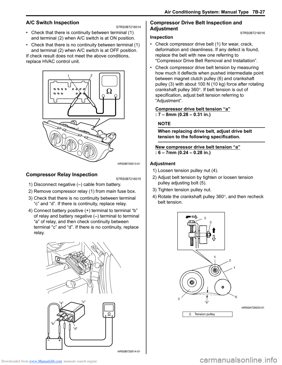
A/C Switch InspectionS7RS0B7216014
• Check that there is continuity between terminal (1) and terminal (2) when A/C s witch is at ON position.
• Check that there is no continuity between terminal (1) and terminal (2) when A/C s witch is at OFF position.
If check result does not meet the above conditions,
replace HVAC control unit.
Compressor Relay InspectionS7RS0B7216015
1) Disconnect negative (–) cable from battery.
2) Remove compressor relay (1) from main fuse box.
3) Check that there is no continuity between terminal “c” and “d”. If there is continuity, replace relay.
4) Connect battery positive (+ ) terminal to terminal “b”
of relay and battery negative (–) terminal to terminal
“a” of relay, and then check continuity between
terminal “c” and “d”. If there is no continuity, replace
relay.
Compressor Drive Belt Inspection and
Adjustment
S7RS0B7216016
Inspection
• Check compressor drive belt (1) for wear, crack, deformation and cleanliness. If any defect is found,
replace the belt with new one referring to
“Compressor Drive Belt Re moval and Installation”.
• Check compressor drive belt tension by measuring how much it deflects when pushed intermediate point
between magnet clutch pulley (6) and crankshaft
pulley (3) with about 100 N (10 kg) force after rotating
crankshaft pulley 360 °. If belt tension is out of
specification, adjust belt tension referring to
“Adjustment”.
Compressor drive belt tension
“a”
: 7 – 8mm (0.28 – 0.31 in.)
NOTE
When replacing drive belt, adjust drive belt
tension to the following specification.
New compressor dr ive belt tension “a”
: 6 – 7mm (0.24 – 0.28 in.)
Adjustment 1) Loosen tension pulley nut (4).
2) Adjust belt tension by ti ghten or loosen tension
pulley adjusting bolt (5).
3) Tighten tension pulley nut.
4) Rotate the crankshaft pulley 360 °, and then recheck
belt tension.
1 2
I4RS0B720013-01
"d"
"b" "a"
"c"
1
I4RS0B720014-01
2. Tension pulley
I4RS0A720033-01