2008 SUZUKI SWIFT Section 9
[x] Cancel search: Section 9Page 963 of 1496
Downloaded from www.Manualslib.com manuals search engine Air Conditioning System: Manual Type 7B-15
A/C System Inspection at ECMS7RS0B7214004
Voltage Check
When checking voltage at ECM connector terminals related to A/C system, refer to “DTC P2101: Throttle Actuator
Control Motor Circuit Range / Performance in Section 1A”.
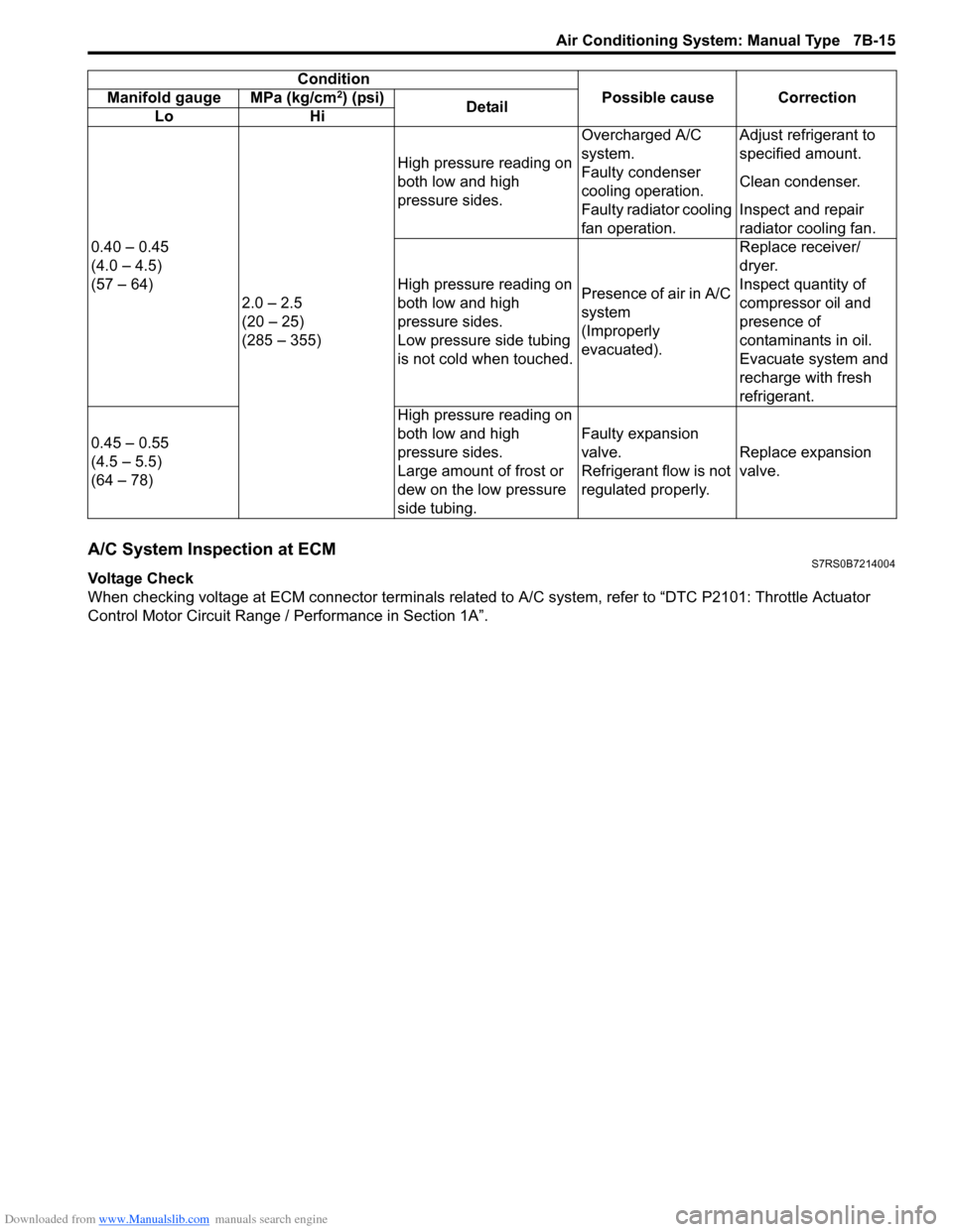
0.40 – 0.45
(4.0 – 4.5)
(57 – 64)
2.0 – 2.5
(20 – 25)
(285 – 355) High pressure reading on
both low and high
pressure sides.
Overcharged A/C
system.
Adjust refrigerant to
specified amount.
Faulty condenser
cooling operation. Clean condenser.
Faulty radiator cooling
fan operation. Inspect and repair
radiator cooling fan.
High pressure reading on
both low and high
pressure sides.
Low pressure side tubing
is not cold when touched. Presence of air in A/C
system
(Improperly
evacuated).Replace receiver/
dryer.
Inspect quantity of
compressor oil and
presence of
contaminants in oil.
Evacuate system and
recharge with fresh
refrigerant.
0.45 – 0.55
(4.5 – 5.5)
(64 – 78) High pressure reading on
both low and high
pressure sides.
Large amount of frost or
dew on the low pressure
side tubing.Faulty expansion
valve.
Refrigerant flow is not
regulated properly.
Replace expansion
valve.
Condition
Possible cause Correction
Manifold gauge MPa (kg/cm
2) (psi)
Detail
Lo Hi
Page 969 of 1496
Downloaded from www.Manualslib.com manuals search engine Air Conditioning System: Manual Type 7B-21
Removal of Manifold Gauge Set
WARNING!
High pressure side is under high pressure.
Therefore, be careful not to get injured
especially on your eyes and skin.
For the A/C system charged with the specified amount of
refrigerant, remove manifold gauge set as follows:
1) Close low pressure side valve of manifold gauge set. (The high pressure side valve is closed continuously
during the process of charging.)
2) Close refrigerant container valve.
3) Stop engine.
4) Using shop rag, remove charging hoses from service valves. This operation must be performed quickly.
5) Put caps on service valves.
Check A/C System for Refrigerant Leaks
Whenever a refrigerant leak is suspected in the system
or any service operation has been performed which may
result in malfunction of lines and connections, it is
advisable to check for leaks.
Common sense should be used during refrigerant leak
test, since the need and extent of any such test will, in
general, depend upon the nature of a complaint and the
type of a service performed on the system.
Liquid leak detector
WARNING!
• To prevent explosions and fires, make sure that there are no flammables in the vicinity.
• When the refrigerant exposed to fire, it turns into a poisonous gas (phosgene). Do
not inhale this gas.
There is a number of fittings and places throughout the
A/C system where a liquid leak detector solution may be
used to pinpoint refrigerant leaks.
By merely applying the solution to the area in question
with a swab, such as attached to the cap of a vial,
bubbles will form within seconds if there is a leak.
For confined areas, such as sections of the evaporator
and condenser, an electronic (refrigerant) leak detector
is more practical fo r determining leaks.
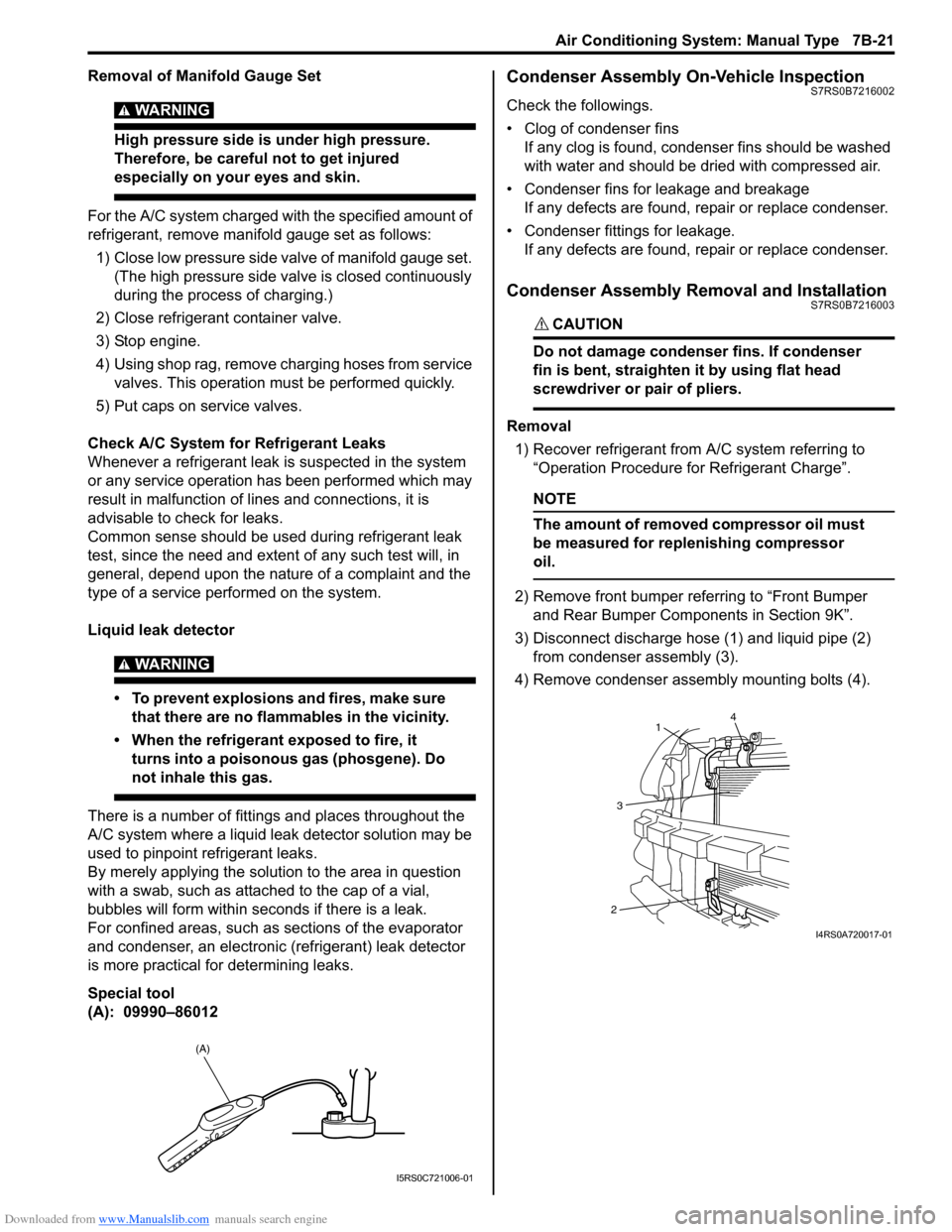
Special tool
(A): 09990–86012
Condenser Assembly On-Vehicle InspectionS7RS0B7216002
Check the followings.
• Clog of condenser fins If any clog is found, cond enser fins should be washed
with water and should be dried with compressed air.
• Condenser fins for leakage and breakage If any defects are found, repair or replace condenser.
• Condenser fittings for leakage. If any defects are found, repair or replace condenser.
Condenser Assembly Removal and InstallationS7RS0B7216003
CAUTION!
Do not damage condenser fins. If condenser
fin is bent, straighten it by using flat head
screwdriver or pair of pliers.
Removal
1) Recover refrigerant from A/C system referring to “Operation Procedure for Refrigerant Charge”.
NOTE
The amount of removed compressor oil must
be measured for replenishing compressor
oil.
2) Remove front bumper referring to “Front Bumper and Rear Bumper Components in Section 9K”.
3) Disconnect discharge hose (1) and liquid pipe (2) from condenser assembly (3).
4) Remove condenser assembly mounting bolts (4).
(A)
I5RS0C721006-01
4
1
3
2
I4RS0A720017-01
Page 970 of 1496
Downloaded from www.Manualslib.com manuals search engine 7B-22 Air Conditioning System: Manual Type
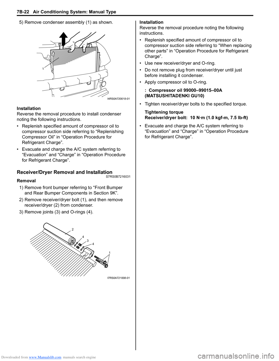
5) Remove condenser assembly (1) as shown.
Installation
Reverse the removal procedure to install condenser
noting the following instructions.
• Replenish specified amount of compressor oil to compressor suction side referring to “Replenishing
Compressor Oil” in “Operation Procedure for
Refrigerant Charge”.
• Evacuate and charge the A/C system referring to “Evacuation” and “Charge” in “Operation Procedure
for Refrigerant Charge”.
Receiver/Dryer Removal and InstallationS7RS0B7216031
Removal
1) Remove front bumper referring to “Front Bumper and Rear Bumper Components in Section 9K”.
2) Remove receiver/dryer bolt (1), and then remove receiver/dryer (2) from condenser.
3) Remove joints (3) and O-rings (4). Installation
Reverse the removal procedure noting the following
instructions.
• Replenish specified amount of compressor oil to
compressor suction side referring to “When replacing
other parts” in “Operation Procedure for Refrigerant
Charge”.
• Use new receiver/dryer and O-ring.
• Do not remove plug from receiver/dryer until just before installin g it condenser.
• Apply compressor oil to O-ring.
: Compressor oil 99000–99015–00A
(MATSUSHITADENKI GU10)
• Tighten receiver/dryer bolts to the specified torque. Tightening torque
Receiver/dryer bolt: 10 N· m (1.0 kgf-m, 7.5 lb-ft)
• Evacuate and charge the A/C system referring to “Evacuation” and “Charge” in “Operation Procedure
for Refrigerant Charge”.
1
I4RS0A720018-01
1
4
4
3
2
I7RS0A721008-01
Page 972 of 1496

Downloaded from www.Manualslib.com manuals search engine 7B-24 Air Conditioning System: Manual Type
HVAC Unit Removal and InstallationS7RS0B7216006
Removal1) Disconnect negative (–) cable from battery.
2) Disable air bag system referring to “Disabling Air Bag System in Section 8B”.
3) Recover refrigerant from A/C system with recovery and recycling equipment referring to “Recovery” in
“Operation Procedure for Refrigerant Charge”.
4) Remove cowl top panel referring to “Cowl Top Components in Section 9K”.
5) Drain engine coolant, and then disconnect heater hoses (1) from HVAC unit (2).
6) Remove instrument panel from vehicle body referring to “Audio Unit Re moval and Installation in
Section 9C”.
7) Loosen suction hose and liquid pipe bolt (4).
8) Remove nuts (3).
9) Remove HVAC unit from vehicle body. Installation
Reverse removal procedure noting the following
instructions.
• Replenish specified amount of compressor oil to
compressor suction side referring to “Replenishing
Compressor Oil” in “Operation Procedure for
Refrigerant Charge”.
• Install the padding (1) to the installation hole uniformly.
• Evacuate and charge the A/C system referring to “Evacuation” and “Charge” in “Operation Procedure
for Refrigerant Charge”.
• Adjust control cables referr ing to “HVAC Control Unit
Removal and Installati on in Section 7A”.
• Enable air bag system referring to “Enabling Air Bag System in Section 8B”.
Evaporator InspectionS7RS0B7216007
Check the followings.
• Clog of A/C evaporator fins.If any clogs are found, A/C evaporator fins should be
washed with water, and then should be dried with
compressed air.
• A/C evaporator fins for leakage and breakage. If any defects are found, repair or replace A/C
evaporator.
• A/C evaporator fittings for leakage. If any defects are found, repair or replace A/C
evaporator.
2. Blower upper case 8. Temperature control door assembly 14. Temperature control lever 20. Packing
3. Air intake control actuator 9. Blower motor resistor 15. Airflow control lever21. Filter cover (if equipped)
4. HVAC Air filter (if equipped) 10. Blower lower case 16. Evaporator22. Drain hose
5. Heater unit upper case 11. Blower motor 17. O-ring23. Cable lock clamp
6. Foot duct 12. Heater unit lower case 18. Expansion valve: Do not reuse.
3
2
3
3
1
4
I4RS0B720009-01
1
I4RS0B720010-01
Page 980 of 1496

Downloaded from www.Manualslib.com manuals search engine 7B-32 Air Conditioning System: Manual Type
Relief Valve Removal and InstallationS7RS0B7216030
Removal1) Recover refrigerant fr om the A/C system with
recovery and recycling equipment referring to
“Recovery” in “Operation Procedure for Refrigerant
Charge”.
2) Remove relief valve (1) from compressor (2). Installation
Reverse removal procedure nothing the following
instructions.
• Use new O-ring.
• Apply compressor oil to O-ring.
• Tighten relive valve to the specified torque.
Tightening torque
Relief valve (a): 8 N·m (0.8 kgf-m, 6.0 lb-ft)
• Evacuate and charge the A/C system referring to “Evacuation” and “Charge” in “Operation Procedure
for Refrigerant Charge”.
Specifications
Tightening Torque SpecificationsS7RS0B7217001
NOTE
The specified tightening torque is also described in the following.
“Compressor Assembly Components”
Reference:
For the tightening torque of fastener not specified in this section, refer to “Fasteners Information in Section 0A”.
12I4RS0A720048-01
(a)I4RS0A720049-01
Fastening part
Tightening torque
Note
N ⋅mkgf-mlb-ft
Receiver/dryer bolt 10 1.0 7.5 �)
Expansion valve mount bolt 3.5 0.35 2.5 �)
A/C refrigerant pressure sensor 11 1.1 8.0 �)
Armature plate bolt 15 1.5 11.0 �)
Relief valve 8 0.8 6.0 �)
Page 982 of 1496

Downloaded from www.Manualslib.com manuals search engine 7B-34 Air Conditioning System: Automatic Type
Automatic Type
Precautions
A/C System CautionS7RS0B7220001
Refer to “A/C System Caution”.
Precautions in Diagnosing TroubleS7RS0B7220002
• Do not disconnect couplers from HVAC control module, battery cable from battery, HVAC control module ground
wire harness from body or main fuse before confirming diagnostic information (diagnostic trouble code) stored in
HVAC control module memory.
• Diagnostic information (diagnostic trouble code) stored in HVAC control module can be checked by display of HVAC
control module. Also, it can be checked by using SU ZUKI scan tool. Before checking diagnostic information
(diagnostic trouble code), read this manual and operator's manual for SUZUKI scan tool to know how to read
diagnostic information (diagnostic trouble code).
• When trouble is diagnosed using diagnostic information (diagnostic trouble code) on display of HVAC control
module, keep in your mind that each diagnostic inform ation (diagnostic trouble code) has priority, and only
diagnostic information (diagnostic troub le code) which has the highest priority is indicated. Therefore, after
troubleshooting the malfunction, make sure if there exists any other diagnostic information (diagnostic trouble
code).
• Be sure to read “Precautions for Electrical Circuit Service in Section 00” before inspection.
Precautions on Servicing A/C SystemS7RS0B7220003
Refer to “Precautions on Servicing A/C System”.
General Description
Auto A/C System DescriptionS7RS0B7221001
The automatic type air conditioning system (auto A/C) is pr ovided with the function to automatically control the inside
air temperature, fan speed, air flow outl et direction and air intake position by HVAC control module in addition to
functions of the manual type air conditioning system (manua l A/C). Once the inside air temperature is set using the
temperature selector, HVAC control module automatically controls the inside air temperature at the constant level at all
times based on the inside air temperature, outside ai r temperature, amount of sunlight and engine coolant
temperature detected respectively by the inside air te mperature sensor, outside air temperature sensor, sunload
sensor and ECT sensor. At this time, “FULL AUTO A/ C” appears on the display of HVAC control module.
With the air intake selector pushed in the above state, it is possible to select any position of the air intake actuator.
Then, “FULL AUTO A/C” on the display changes to “AUTO A/C”.
Page 987 of 1496
Downloaded from www.Manualslib.com manuals search engine Air Conditioning System: Automatic Type 7B-39
Diagnostic Information and Procedures
A/C System Symptom DiagnosisS7RS0B7224001
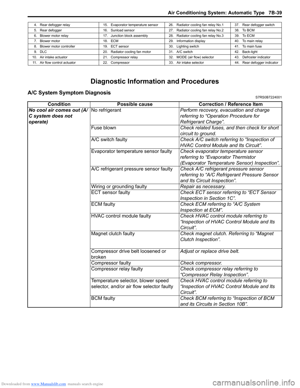
4. Rear defogger relay 15. Evaporator temperature sensor 26. Radiator cooling fan relay No.1 37. Rear defogger switch
5. Rear defogger 16. Sunload sensor 27. Radiator cooling fan relay No.2 38. To BCM
6. Blower motor relay 17. Junction block assembly 28. Radiator cooling fan relay No.3 39. To ECM
7. Blower motor 18. ECM 29. Information display 40. To main relay
8. Blower motor controller 19. ECT sensor 30. Lighting switch 41. To main fuse
9. DLC 20. Radiator cooling fan motor 31. A/C switch 42. Back-light
10. Air intake actuator 21. Compressor relay 32. MODE (air flow) selector 43. Defroster indicator 11. Air flow control actuator 22. Compressor 33. Air intake selector 44. Rear defogger indicator
Condition Possible cause Correction / Reference Item
No cool air comes out (A/
C system does not
operate) No refrigerant
Perform recovery, evacuation and charge
referring to “Operation Procedure for
Refrigerant Charge”.
Fuse blown Check related fuses, and then check for short
circuit to ground.
A/C switch faulty Check A/C switch referring to “Inspection of
HVAC Control Module and Its Circuit”.
Evaporator temperature sensor faulty Check evaporator temperature sensor
referring to “Evaporator Thermistor
(Evaporator Temperature Sensor) Inspection”.
A/C refrigerant pressure sensor faulty Check A/C refrigerant pressure sensor
referring to “A/C Refrigerant Pressure Sensor
and Its Circuit Inspection”.
Wiring or grounding faulty Repair as necessary.
ECT sensor faulty Check ECT sensor referring to “ECT Sensor
Inspection in Section 1C”.
ECM faulty Check ECM referring to “A/C System
Inspection at ECM”.
HVAC control module faulty Check HVAC control module referring to
“Inspection of HVAC Control Module and Its
Circuit”.
Magnet clutch faulty Check magnet clutch. Referring to “Magnet
Clutch Inspection”.
Compressor drive belt loosened or
broken Adjust or replace drive belt.
Compressor faulty Check compressor.
Compressor relay faulty Check compressor relay referring to
“Compressor Relay Inspection”.
Temperature selector, blower speed
selector, and/or air flow selector faulty Check HVAC control module referring to
“Inspection of HVAC Control Module and Its
Circuit”.
BCM faulty Check BCM referring to “Inspection of BCM
and its Circuits in Section 10B”.
Page 988 of 1496
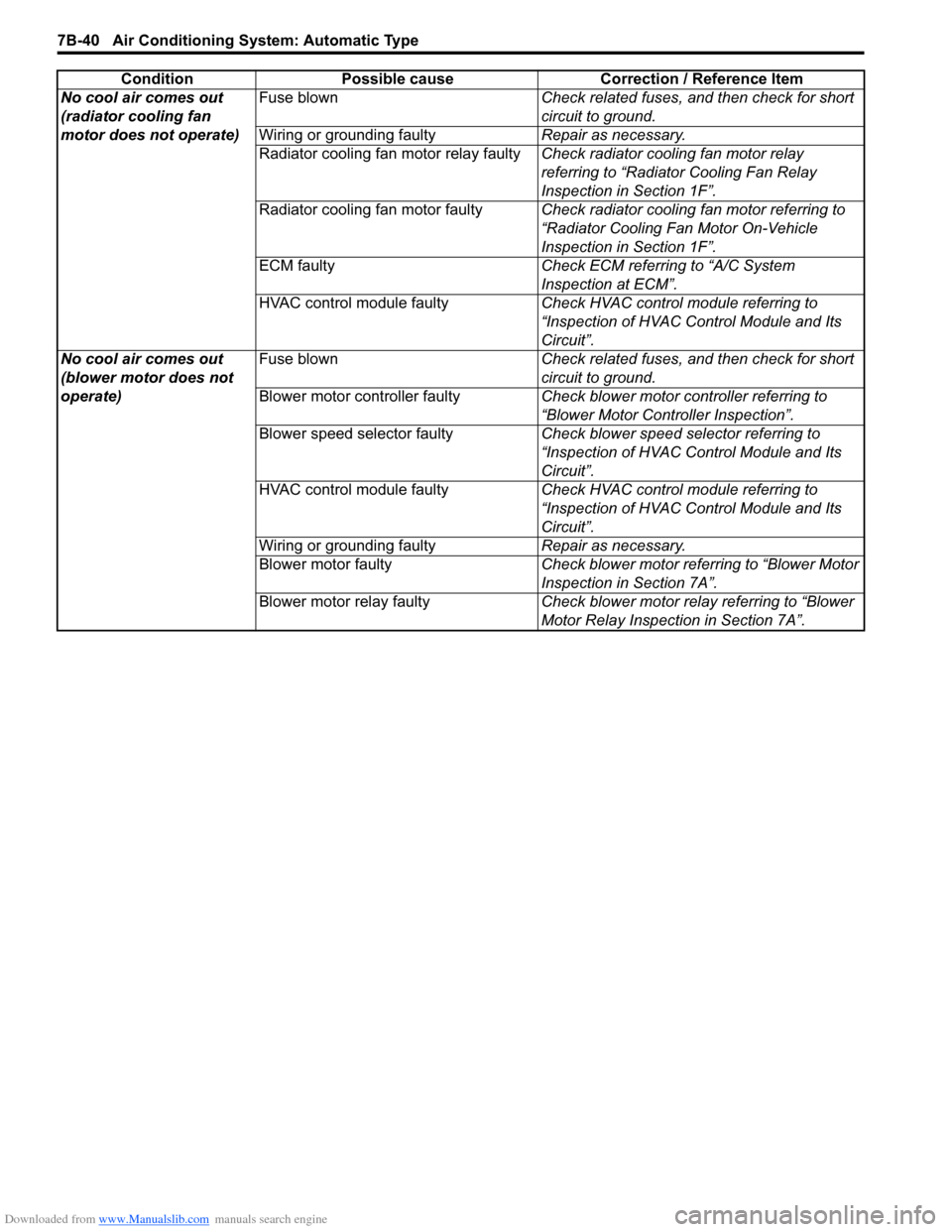
Downloaded from www.Manualslib.com manuals search engine 7B-40 Air Conditioning System: Automatic Type
No cool air comes out
(radiator cooling fan
motor does not operate)Fuse blown
Check related fuses, and then check for short
circuit to ground.
Wiring or grounding faulty Repair as necessary.
Radiator cooling fan motor relay faulty Check radiator cooling fan motor relay
referring to “Radiator Cooling Fan Relay
Inspection in Section 1F”.
Radiator cooling fan motor faulty Check radiator cooling fan motor referring to
“Radiator Cooling Fan Motor On-Vehicle
Inspection in Section 1F”.
ECM faulty Check ECM referring to “A/C System
Inspection at ECM”.
HVAC control module faulty Check HVAC control module referring to
“Inspection of HVAC Control Module and Its
Circuit”.
No cool air comes out
(blower motor does not
operate) Fuse blown
Check related fuses, and then check for short
circuit to ground.
Blower motor controller faulty Check blower motor controller referring to
“Blower Motor Controller Inspection”.
Blower speed selector faulty Check blower speed selector referring to
“Inspection of HVAC Control Module and Its
Circuit”.
HVAC control module faulty Check HVAC control module referring to
“Inspection of HVAC Control Module and Its
Circuit”.
Wiring or grounding faulty Repair as necessary.
Blower motor faulty Check blower motor referring to “Blower Motor
Inspection in Section 7A”.
Blower motor relay faulty Check blower motor relay referring to “Blower
Motor Relay Inspection in Section 7A”.
Condition Possible cause Correction / Reference Item