2008 SUZUKI SWIFT Connection
[x] Cancel search: ConnectionPage 1457 of 1496
Downloaded from www.Manualslib.com manuals search engine Immobilizer Control System: 10C-14
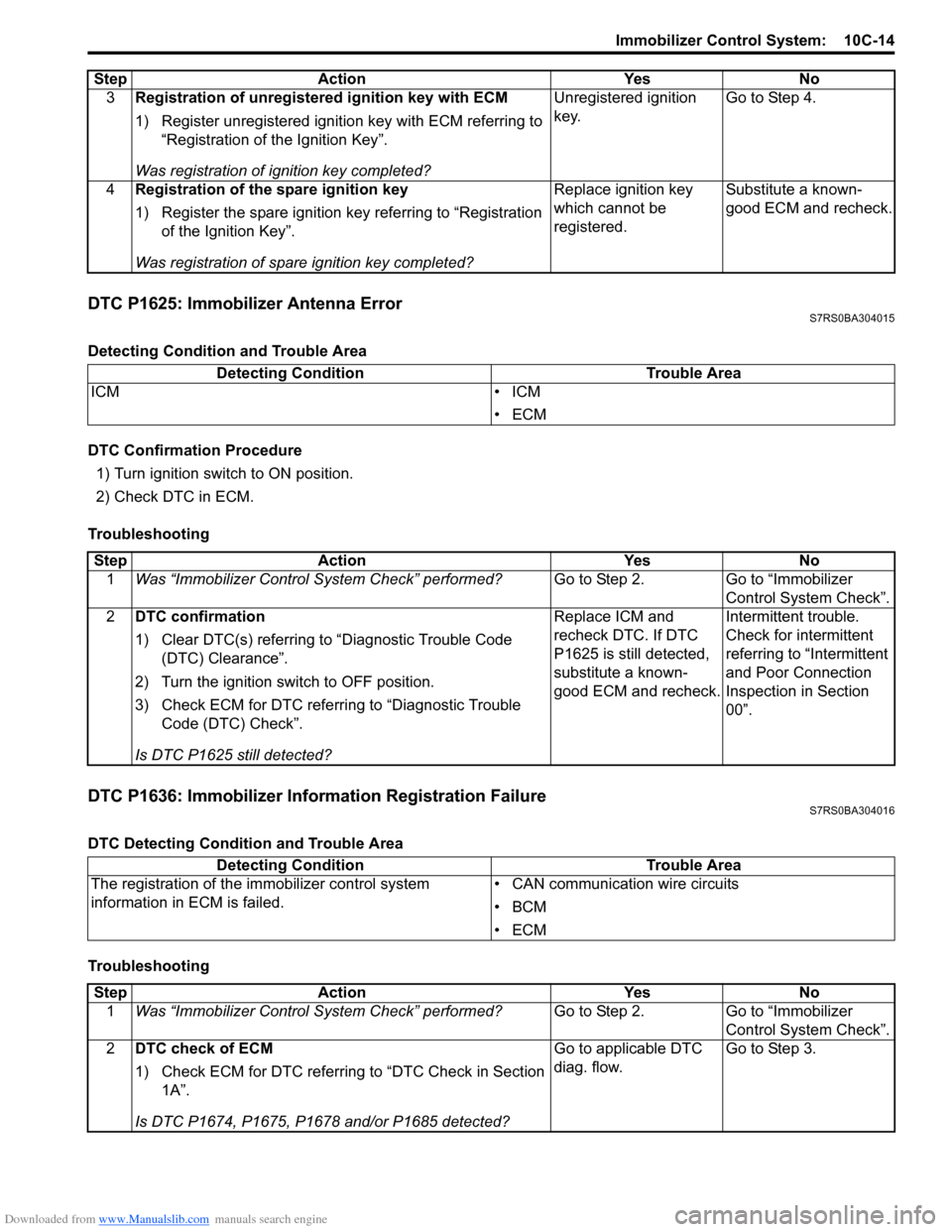
DTC P1625: Immobilizer Antenna ErrorS7RS0BA304015
Detecting Condition and Trouble Area
DTC Confirmation Procedure1) Turn ignition switch to ON position.
2) Check DTC in ECM.
Troubleshooting
DTC P1636: Immobilizer Information Registration FailureS7RS0BA304016
DTC Detecting Condition and Trouble Area
Troubleshooting 3
Registration of unregistered ignition key with ECM
1) Register unregistered igniti on key with ECM referring to
“Registration of the Ignition Key”.
Was registration of ignition key completed? Unregistered ignition
key.
Go to Step 4.
4 Registration of the spare ignition key
1) Register the spare ignition key referring to “Registration
of the Ignition Key”.
Was registration of spare ignition key completed? Replace ignition key
which cannot be
registered.
Substitute a known-
good ECM and recheck.
Step Action Yes No
Detecting Condition
Trouble Area
ICM • ICM
•ECM
StepAction YesNo
1 Was “Immobilizer Control S ystem Check” performed? Go to Step 2.Go to “Immobilizer
Control System Check”.
2 DTC confirmation
1) Clear DTC(s) referring to “Diagnostic Trouble Code
(DTC) Clearance”.
2) Turn the ignition switch to OFF position.
3) Check ECM for DTC referring to “Diagnostic Trouble Code (DTC) Check”.
Is DTC P1625 still detected? Replace ICM and
recheck DTC. If DTC
P1625 is still detected,
substitute a known-
good ECM and recheck.
Intermittent trouble.
Check for intermittent
referring to “Intermittent
and Poor Connection
Inspection in Section
00”.
Detecting Condition
Trouble Area
The registration of the immobilizer control system
information in ECM is failed. • CAN communication wire circuits
•BCM
•ECM
Step
Action YesNo
1 Was “Immobilizer Control S ystem Check” performed? Go to Step 2.Go to “Immobilizer
Control System Check”.
2 DTC check of ECM
1) Check ECM for DTC referring to “DTC Check in Section
1A”.
Is DTC P1674, P1675, P1678 and/or P1685 detected? Go to applicable DTC
diag. flow.
Go to Step 3.
Page 1458 of 1496
Downloaded from www.Manualslib.com manuals search engine 10C-15 Immobilizer Control System:
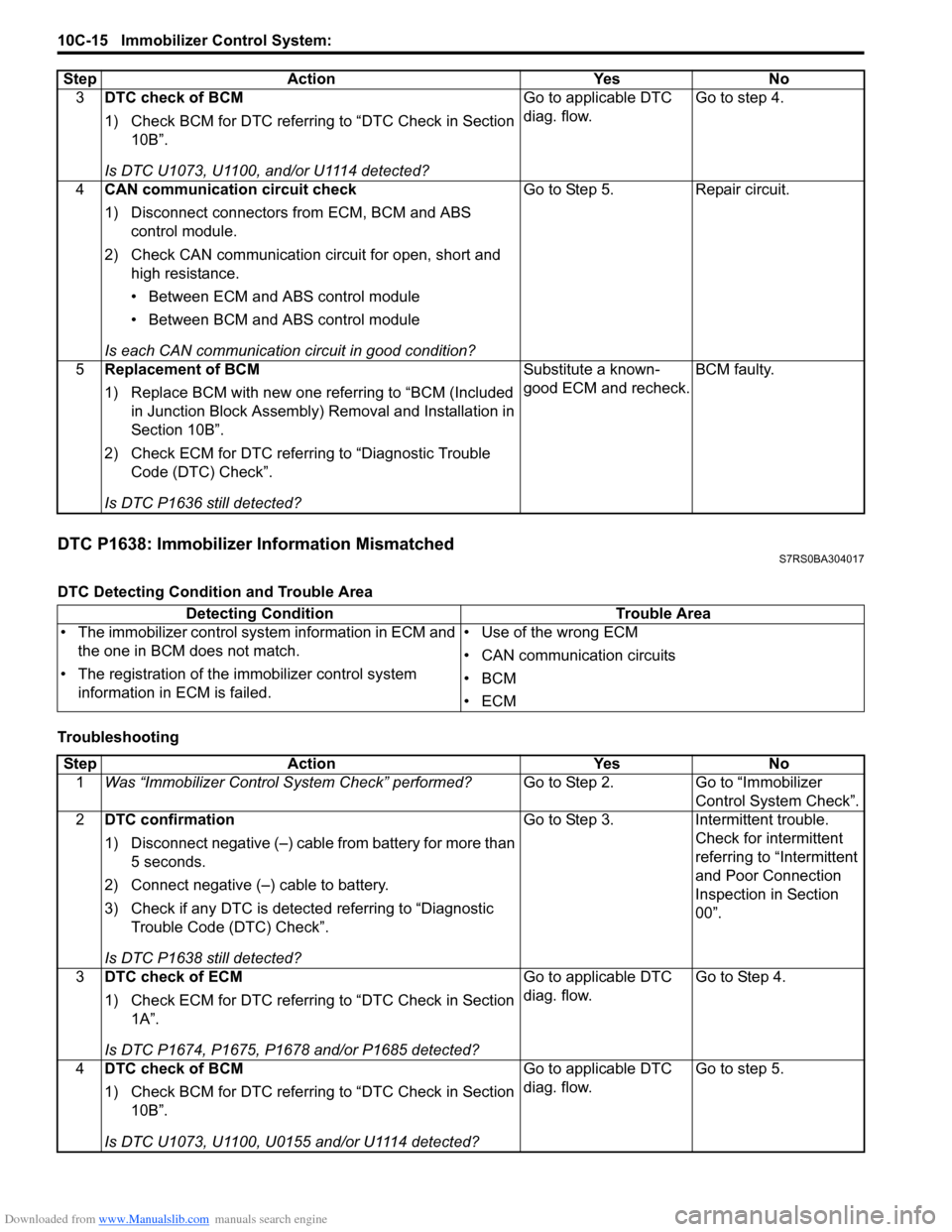
DTC P1638: Immobilizer Information MismatchedS7RS0BA304017
DTC Detecting Condition and Trouble Area
Troubleshooting3
DTC check of BCM
1) Check BCM for DTC referring to “DTC Check in Section
10B”.
Is DTC U1073, U1100, and/or U1114 detected? Go to applicable DTC
diag. flow.
Go to step 4.
4 CAN communication circuit check
1) Disconnect connectors from ECM, BCM and ABS
control module.
2) Check CAN communication circuit for open, short and high resistance.
• Between ECM and ABS control module
• Between BCM and ABS control module
Is each CAN communication circuit in good condition? Go to Step 5. Repair circuit.
5 Replacement of BCM
1) Replace BCM with new one referring to “BCM (Included
in Junction Block Assembly) Removal and Installation in
Section 10B”.
2) Check ECM for DTC referring to “Diagnostic Trouble Code (DTC) Check”.
Is DTC P1636 still detected? Substitute a known-
good ECM and recheck.
BCM faulty.
Step Action Yes No
Detecting Condition
Trouble Area
• The immobilizer control sys tem information in ECM and
the one in BCM does not match.
• The registration of the immobilizer control system
information in ECM is failed. • Use of the wrong ECM
• CAN communication circuits
•BCM
•ECM
Step
Action YesNo
1 Was “Immobilizer Control S ystem Check” performed? Go to Step 2.Go to “Immobilizer
Control System Check”.
2 DTC confirmation
1) Disconnect negative (–) cable from battery for more than
5 seconds.
2) Connect negative (–) cable to battery.
3) Check if any DTC is detecte d referring to “Diagnostic
Trouble Code (DTC) Check”.
Is DTC P1638 still detected? Go to Step 3.
Intermittent trouble.
Check for intermittent
referring to “Intermittent
and Poor Connection
Inspection in Section
00”.
3 DTC check of ECM
1) Check ECM for DTC referring to “DTC Check in Section
1A”.
Is DTC P1674, P1675, P1678 and/or P1685 detected? Go to applicable DTC
diag. flow.
Go to Step 4.
4 DTC check of BCM
1) Check BCM for DTC referring to “DTC Check in Section
10B”.
Is DTC U1073, U1100, U0155 and/or U1114 detected? Go to applicable DTC
diag. flow.
Go to step 5.
Page 1471 of 1496
Downloaded from www.Manualslib.com manuals search engine Keyless Start System: 10E-9
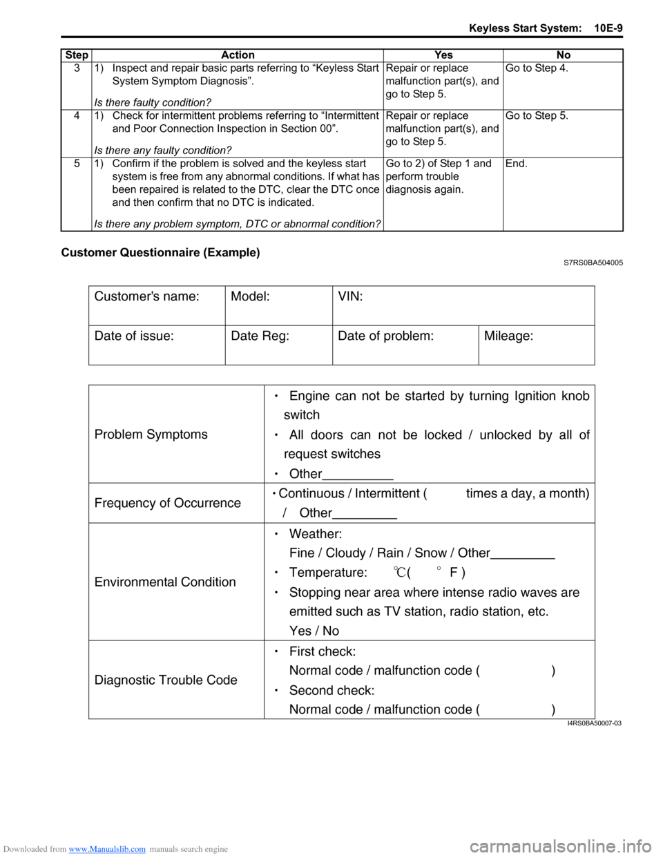
Customer Questionnaire (Example)S7RS0BA504005
3 1) Inspect and repair basic parts referring to “Keyless Start System Symptom Diagnosis”.
Is there faulty condition? Repair or replace
malfunction part(s), and
go to Step 5.
Go to Step 4.
4 1) Check for intermittent problems referring to “Intermittent and Poor Connection Inspection in Section 00”.
Is there any faulty condition? Repair or replace
malfunction part(s), and
go to Step 5.
Go to Step 5.
5 1) Confirm if the problem is solved and the keyless start system is free from any abnormal conditions. If what has
been repaired is related to the DTC, clear the DTC once
and then confirm that no DTC is indicated.
Is there any problem symptom, DTC or abnormal condition? Go to 2) of Step 1 and
perform trouble
diagnosis again.
End.
Step Action Yes No
Customers name:
Model:
VIN:
Date of issue:
Date Reg:
Date of problem:
Mileage:
Problem Symptoms
Engine can not be started by turning Ignition knob
switch
All doors can not be locked / unlocked by all of
request switches
Other
Frequency of Occurrence Continuous / Intermittent ( times a day, a month)
/ Other
Environmental Condition
Weather:
Fine / Cloudy / Rain / Snow / Other
Temperature: (F )
Stopping near area where intense radio waves are
emitted such as TV station, radio station, etc.
Yes / No
Diagnostic Trouble Code
First check:
Normal code / malfunction code ( )
Second check:
Normal code / malfunction code ( )
I4RS0BA50007-03
Page 1484 of 1496
Downloaded from www.Manualslib.com manuals search engine 10E-22 Keyless Start System:
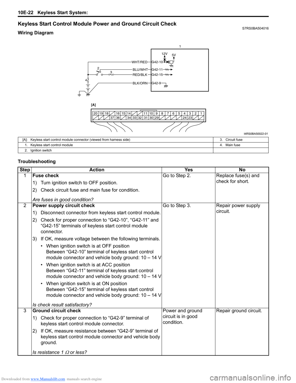
Keyless Start Control Module Power and Ground Circuit CheckS7RS0BA504016
Wiring Diagram
Troubleshooting
BLK/ORNG42-9
G42-15
G42-10
G42-11BLU/WHT
WHT/RED
RED/BLK
5V
12V
1234567891011
141516
36 34 33 32 31 30 29 24 23
37
181920
[A]
4 2
3 1
I4RS0BA50022-01
[A]: Keyless start control module connector (viewed from harness side)
3. Circuit fuse
1. Keyless start control module 4. Main fuse
2. Ignition switch
Step Action YesNo
1 Fuse check
1) Turn ignition switch to OFF position.
2) Check circuit fuse and main fuse for condition.
Are fuses in good condition? Go to Step 2.
Replace fuse(s) and
check for short.
2 Power supply circuit check
1) Disconnect connector from keyless start control module.
2) Check for proper connection to “G42-10”, “G42-11” and
“G42-15” terminals of keyless start control module
connector.
3) If OK, measure voltage between the following terminals. • When ignition switch is at OFF positionBetween “G42-10” terminal of keyless start control
module connector and vehicle body ground: 10 – 14 V
• When ignition switch is at ACC position Between “G42-11” terminal of keyless start control
module connector and vehicle body ground: 10 – 14 V
• When ignition switch is at ON position Between “G42-15” terminal of keyless start control
module connector and vehicle body ground: 10 – 14 V
Is check result satisfactory? Go to Step 3.
Repair power supply
circuit.
3 Ground circuit check
1) Check for proper connection to “G42-9” terminal of
keyless start control module connector.
2) If OK, measure resistance between “G42-9” terminal of keyless start control module connector and vehicle body
ground.
Is resistance 1
Ω or less? Power and ground
circuit is in good
condition.
Repair ground circuit.
Page 1485 of 1496
Downloaded from www.Manualslib.com manuals search engine Keyless Start System: 10E-23
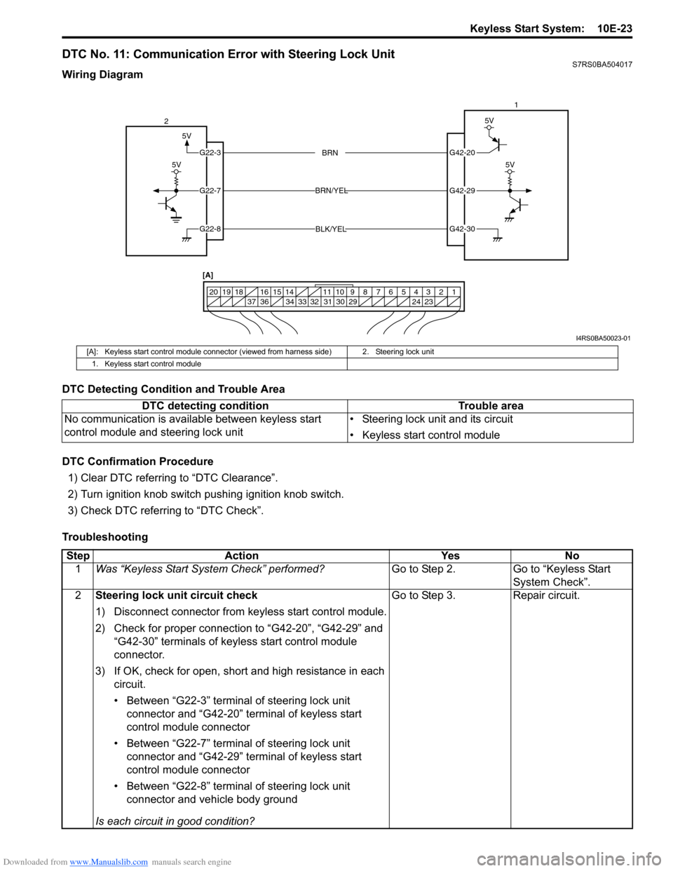
DTC No. 11: Communication Error with Steering Lock UnitS7RS0BA504017
Wiring Diagram
DTC Detecting Condition and Trouble Area
DTC Confirmation Procedure1) Clear DTC referring to “DTC Clearance”.
2) Turn ignition knob switch pushing ignition knob switch.
3) Check DTC referring to “DTC Check”.
Troubleshooting
5V
G42-20
G42-29
G42-30
G22-3
G22-7
G22-8
1234567891011
141516
36 34 33 32 31 30 29 24 23
37
181920
5V
5V
BRN
BRN/YEL
BLK/YEL
5V
2 1
[A]
I4RS0BA50023-01
[A]: Keyless start control module connector (vie wed from harness side) 2. Steering lock unit
1. Keyless start control module
DTC detecting condition Trouble area
No communication is available between keyless start
control module and steering lock unit • Steering lock unit and its circuit
• Keyless start control module
Step
Action YesNo
1 Was “Keyless Start System Check” performed? Go to Step 2.Go to “Keyless Start
System Check”.
2 Steering lock unit circuit check
1) Disconnect connector from keyless start control module.
2) Check for proper connection to “G42-20”, “G42-29” and
“G42-30” terminals of keyless start control module
connector.
3) If OK, check for open, short and high resistance in each circuit.
• Between “G22-3” terminal of steering lock unit connector and “G42-20” terminal of keyless start
control module connector
• Between “G22-7” terminal of steering lock unit connector and “G42-29” terminal of keyless start
control module connector
• Between “G22-8” terminal of steering lock unit connector and vehicle body ground
Is each circuit in good condition? Go to Step 3.
Repair circuit.
Page 1488 of 1496
Downloaded from www.Manualslib.com manuals search engine 10E-26 Keyless Start System:
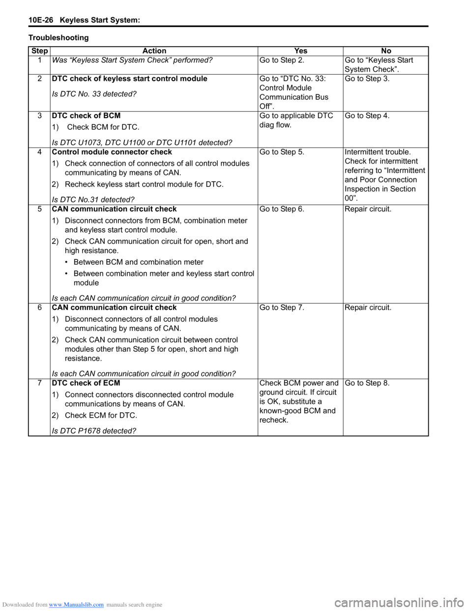
TroubleshootingStep Action Yes No 1 Was “Keyless Start System Check” performed? Go to Step 2. Go to “Keyless Start
System Check”.
2 DTC check of keyless start control module
Is DTC No. 33 detected? Go to “DTC No. 33:
Control Module
Communication Bus
Off”.Go to Step 3.
3 DTC check of BCM
1) Check BCM for DTC.
Is DTC U1073, DTC U1100 or DTC U1101 detected? Go to applicable DTC
diag flow.
Go to Step 4.
4 Control module connector check
1) Check connection of connectors of all control modules
communicating by means of CAN.
2) Recheck keyless start control module for DTC.
Is DTC No.31 detected? Go to Step 5. Intermittent trouble.
Check for intermittent
referring to “Intermittent
and Poor Connection
Inspection in Section
00”.
5 CAN communication circuit check
1) Disconnect connectors from BCM, combination meter
and keyless start control module.
2) Check CAN communication circuit for open, short and high resistance.
• Between BCM and combination meter
• Between combination meter and keyless start control module
Is each CAN communication circuit in good condition? Go to Step 6. Repair circuit.
6 CAN communication circuit check
1) Disconnect connectors of all control modules
communicating by means of CAN.
2) Check CAN communication circuit between control modules other than Step 5 for open, short and high
resistance.
Is each CAN communication circuit in good condition? Go to Step 7. Repair circuit.
7 DTC check of ECM
1) Connect connectors disconnected control module
communications by means of CAN.
2) Check ECM for DTC.
Is DTC P1678 detected? Check BCM power and
ground circuit. If circuit
is OK, substitute a
known-good BCM and
recheck.
Go to Step 8.
Page 1489 of 1496
Downloaded from www.Manualslib.com manuals search engine Keyless Start System: 10E-27
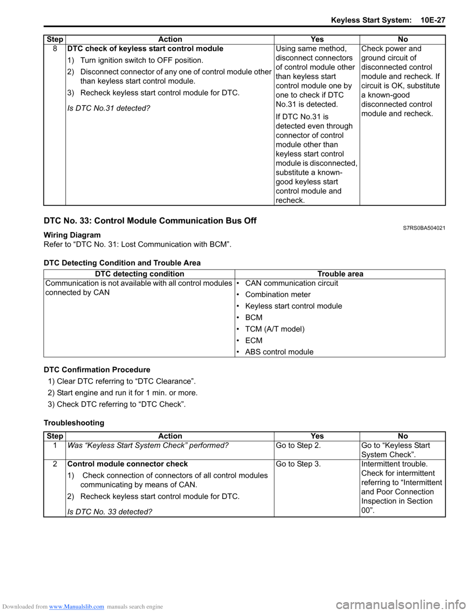
DTC No. 33: Control Module Communication Bus OffS7RS0BA504021
Wiring Diagram
Refer to “DTC No. 31: Lost Communication with BCM”.
DTC Detecting Condition and Trouble Area
DTC Confirmation Procedure1) Clear DTC referring to “DTC Clearance”.
2) Start engine and run it for 1 min. or more.
3) Check DTC referring to “DTC Check”.
Troubleshooting 8
DTC check of keyless start control module
1) Turn ignition switch to OFF position.
2) Disconnect connector of any one of control module other
than keyless start control module.
3) Recheck keyless start control module for DTC.
Is DTC No.31 detected? Using same method,
disconnect connectors
of control module other
than keyless start
control module one by
one to check if DTC
No.31 is detected.
If DTC No.31 is
detected even through
connector of control
module other than
keyless start control
module is disconnected,
substitute a known-
good keyless start
control module and
recheck.Check power and
ground circuit of
disconnected control
module and recheck. If
circuit is OK, substitute
a known-good
disconnected control
module and recheck.
Step Action Yes No
DTC detecting condition
Trouble area
Communication is not availabl e with all control modules
connected by CAN • CAN communication circuit
• Combination meter
• Keyless start control module
•BCM
• TCM (A/T model)
•ECM
• ABS control module
Step
Action YesNo
1 Was “Keyless Start System Check” performed? Go to Step 2.Go to “Keyless Start
System Check”.
2 Control module connector check
1) Check connection of connectors of all control modules
communicating by means of CAN.
2) Recheck keyless start control module for DTC.
Is DTC No. 33 detected? Go to Step 3.
Intermittent trouble.
Check for intermittent
referring to “Intermittent
and Poor Connection
Inspection in Section
00”.
Page 1491 of 1496
Downloaded from www.Manualslib.com manuals search engine Keyless Start System: 10E-29
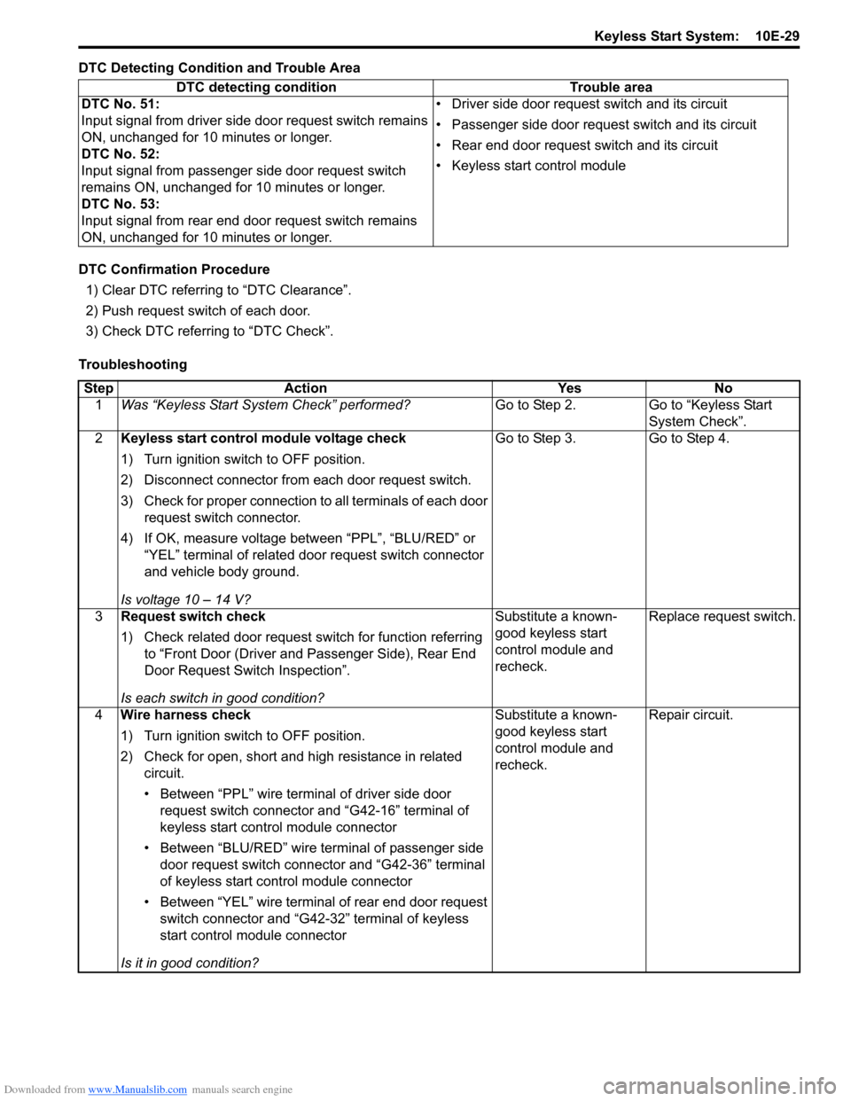
DTC Detecting Condition and Trouble Area
DTC Confirmation Procedure1) Clear DTC referring to “DTC Clearance”.
2) Push request switch of each door.
3) Check DTC referring to “DTC Check”.
Troubleshooting DTC detecting condition Trouble area
DTC No. 51:
Input signal from driver side door request switch remains
ON, unchanged for 10 minutes or longer.
DTC No. 52:
Input signal from passenger side door request switch
remains ON, unchanged for 10 minutes or longer.
DTC No. 53:
Input signal from rear end door request switch remains
ON, unchanged for 10 minutes or longer. • Driver side door request switch and its circuit
• Passenger side door request switch and its circuit
• Rear end door request switch and its circuit
• Keyless start control module
Step
Action YesNo
1 Was “Keyless Start System Check” performed? Go to Step 2.Go to “Keyless Start
System Check”.
2 Keyless start control module voltage check
1) Turn ignition switch to OFF position.
2) Disconnect connector from each door request switch.
3) Check for proper connection to all terminals of each door
request switch connector.
4) If OK, measure voltage between “PPL”, “BLU/RED” or “YEL” terminal of related door request switch connector
and vehicle body ground.
Is voltage 10 – 14 V? Go to Step 3.
Go to Step 4.
3 Request switch check
1) Check related door request switch for function referring
to “Front Door (Driver and Passenger Side), Rear End
Door Request Switch Inspection”.
Is each switch in good condition? Substitute a known-
good keyless start
control module and
recheck.
Replace request switch.
4 Wire harness check
1) Turn ignition switch to OFF position.
2) Check for open, short and high resistance in related
circuit.
• Between “PPL” wire terminal of driver side door request switch connector and “G42-16” terminal of
keyless start control module connector
• Between “BLU/RED” wire terminal of passenger side door request switch connector and “G42-36” terminal
of keyless start control module connector
• Between “YEL” wire terminal of rear end door request switch connector and “G42-32” terminal of keyless
start control module connector
Is it in good condition? Substitute a known-
good keyless start
control module and
recheck.
Repair circuit.