2008 SUZUKI SWIFT tools
[x] Cancel search: toolsPage 375 of 1496
Downloaded from www.Manualslib.com manuals search engine Engine Cooling System: 1F-12
Specifications
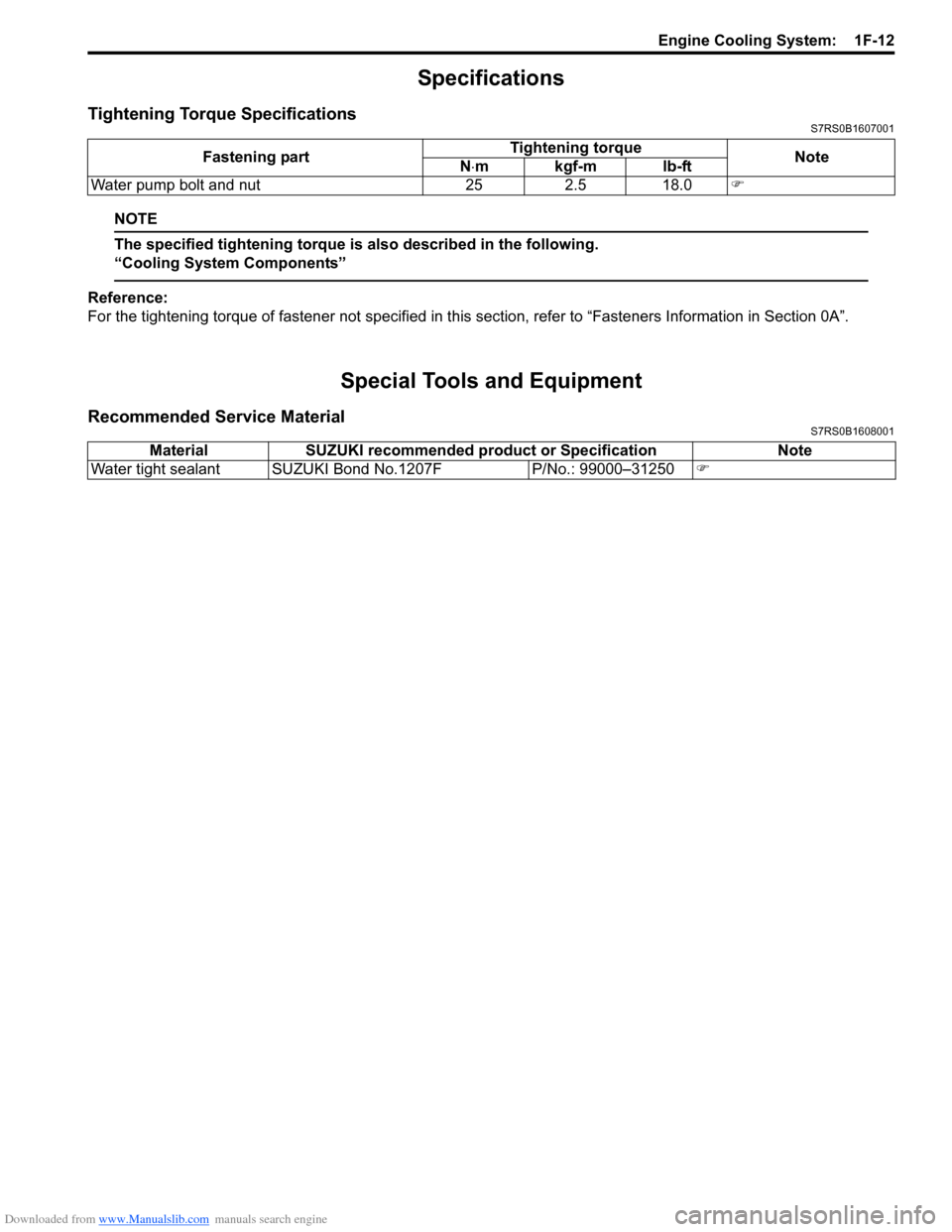
Tightening Torque SpecificationsS7RS0B1607001
NOTE
The specified tightening torque is also described in the following.
“Cooling System Components”
Reference:
For the tightening torque of fastener not specified in this section, refer to “Fasteners Information in Section 0A”.
Special Tools and Equipment
Recommended Service MaterialS7RS0B1608001
Fastening part Tightening torque
Note
N ⋅mkgf-mlb-ft
Water pump bolt and nut 25 2.5 18.0 �)
MaterialSUZUKI recommended product or Specification Note
Water tight sealant SUZUKI Bond No.1207F P/No.: 99000–31250�)
Page 377 of 1496

Downloaded from www.Manualslib.com manuals search engine Fuel System: 1G-2
Fuel Pump DescriptionS7RS0B1701003
The fuel pump (1) is an in-tank type electric pump.
Incorporated in the pump assembly are;
a fuel filter (2) and a fuel pressure regulator (3) are
included and a fuel level gauge (4) is attached.
Addition of the fuel pressure regulator to the fuel pump
makes it possible to mainta in the fuel pressure at
constant level and ECM controls compensation for
variation in the intake manifold pressure.
Schematic and Routing Diagram
Fuel Delivery System DiagramS7RS0B1702001
Diagnostic Information and Procedures
Fuel Pressure InspectionS7RS0B1704001
WARNING!
Before starting the following procedure, be
sure to observe “Precautions on Fuel System
Service” in order to reduce the risk or fire
and personal injury.
1) Relieve fuel pressure in fuel feed line referring to
“Fuel Pressure Relief Procedure”.
2) Disconnect fuel feed hose from fuel delivery pipe.
3) Connect special tools and hose between fuel feed hose (1) and fuel delivery pipe as shown in figure,
and clamp hoses securely in order to ensure that no
leaks occur during checking.
Special tool
(A): 09912–58442
(B): 09912–58432
(C): 09912–58490
1
3
2
4
I6RS0C170001-01
4
6 7
8
12
2 3
11
10
5
1
9
I6RS0C170002-01
1. Fuel tank
5. Fuel injector9. EVAP canister
2. Fuel pump 6. Fuel feed line10. Fuel filter
3. Fuel pressure regulator 7. Fuel vapor line 11. Main fuel level sensor
4. Delivery pipe 8. Intake manifold12. EVAP canister purge valve
1
(C) (B)
(A)
I3RM0A170004-01
Page 378 of 1496
Downloaded from www.Manualslib.com manuals search engine 1G-3 Fuel System:
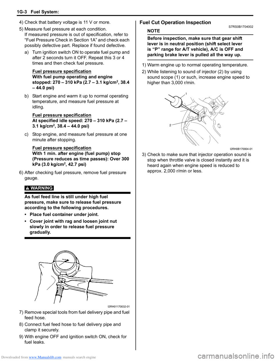
4) Check that battery voltage is 11 V or more.
5) Measure fuel pressure at each condition.If measured pressure is out of specification, refer to
“Fuel Pressure Check in Section 1A” and check each
possibly defective part. Replace if found defective.
a) Turn ignition switch ON to operate fuel pump and after 2 seconds turn it OFF. Repeat this 3 or 4
times and then check fuel pressure.
Fuel pressure specification
With fuel pump operating and engine
stopped: 270 – 310 kPa (2.7 – 3.1 kg/cm2, 38.4
– 44.0 psi)
b) Start engine and warm it up to normal operating temperature, and measure fuel pressure at
idling.
Fuel pressure specification
At specified idle speed: 270 – 310 kPa (2.7 –
3.1 kg/cm2, 38.4 – 44.0 psi)
c) Stop engine, and measure fuel pressure at one minute after stopping.
Fuel pressure specification
With 1 min. after engine (fuel pump) stop
(Pressure reduces as time passes): Over 300
kPa (3.0 kg/cm
2, 42.7 psi)
6) After checking fuel pressure, remove fuel pressure gauge.
WARNING!
As fuel feed line is still under high fuel
pressure, make sure to release fuel pressure
according to the following procedures.
• Place fuel container under joint.
• Cover joint with rag and loosen joint nut slowly in order to release fuel pressure
gradually.
7) Remove special tools from fuel delivery pipe and fuel feed hose.
8) Connect fuel feed hose to fuel delivery pipe and clamp it securely.
9) With engine OFF and ignition switch ON, check for fuel leaks.
Fuel Cut Operation InspectionS7RS0B1704002
NOTE
Before inspection, make sure that gear shift
lever is in neutral positi on (shift select lever
is “P” range for A/T vehicle), A/C is OFF and
parking brake lever is pulled all the way up.
1) Warm engine up to normal operating temperature.
2) While listening to sound of injector (2) by using sound scope (1) or such, increase engine speed to
higher than 3,000 r/min.
3) Check to make sure that injector operation sound is stop when throttle valve is closed instantly and it is
heard again when engine speed is reduced to
approx. 2,000 r/min or less.
I2RH01170032-01
I2RH0B170004-01
Page 384 of 1496

Downloaded from www.Manualslib.com manuals search engine 1G-9 Fuel System:
Installation
Reverse removal procedure for installation noting the
following.
• Replace injector O-ring (1) with new one using care not to damage it.
• Check if cushion (2) is scor ed or damaged. If it is,
replace with new one.
• Apply thin coat of fuel to O-rings (1) and then install injectors (3) into delivery pipe (4) and cylinder head.
Make sure that injectors rota te smoothly (6). If not,
probable cause is incorrect installation of O-ring.
Replace O-ring with new one.
• Tighten delivery pipe bolts (5) to specified torque and make sure that inject ors rotate smoothly.
Tightening torque
Fuel delivery pipe bolt (a): 25 N·m (2.5 kgf-m, 18.0
lb-ft)
• After installation, with engine OFF and ignition switch ON, check for fuel leaks around fuel line connection.Fuel Injector InspectionS7RS0B1706009
WARNING!
Before starting the following procedure, be
sure to observe “Precautions on Fuel System
Service” in order to reduce the risk or fire
and personal injury.
1) Relieve fuel pressure according to “Fuel Pressure Relief Procedure” if equipped.
2) Disconnect fuel feed hose from delivery pipe.
3) Set special tools as follows.
Special tool
(A): 09912–58421
(B): 09930–88530
(C): 09912–57610
a) Fit washer (1) (inside diameter 13.5 – 14.5 mm (0.532 – 0.570 in.)) to injector (2), and then
install injector to special tool (A).
b) Connect special tool (B) to injector.
c) Install special tool (C) to special tool (A).
d) Connect fuel feed hose to special tool (A).
I3RM0A170011-01
(B)
(A)
(A) (C)
2
1
I6RW0B170014-01
Page 392 of 1496

Downloaded from www.Manualslib.com manuals search engine 1G-17 Fuel System:
Special Tools and Equipment
Special ToolS7RS0B1708001
09912–5761009912–58421
Injector checking tool plate Checking tool set
�) This kit includes the
following items. 1. Tool body
and washer, 2. Body plug, 3.
Body attachment-1, 4.
Holder, 5. Return hose and
clamp, 6. Body attachment-2
and washer, 7. Hose
attachment-1, 8. Hose
attachment-2�)
09912–58432 09912–58442
Fuel pressure gauge hose Fuel pressure gauge
This tool is included in fuel
pressure gauge set (09912-
58413). �) This tool is included in fuel
pressure gauge set (09912-
58413).
�)
09912–58490 09919–47020
3-way joint & hose Quick joint remover
�)�)
09930–88530 SUZUKI scan tool
Injector test lead —
�) This kit includes following
items. 1. Tech 2, 2. PCMCIA
card, 3. DLC cable, 4. SAE
16/19 adapter, 5. Cigarette
cable, 6. DLC loop back
adapter, 7. Battery power
cable, 8. RS232 cable, 9.
RS232 adapter, 10. RS232
loop back connector, 11.
Storage case, 12.�)
Page 401 of 1496
Downloaded from www.Manualslib.com manuals search engine Ignition System: 1H-9
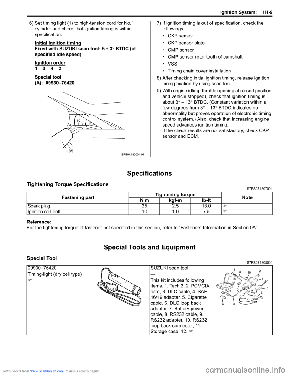
6) Set timing light (1) to high-tension cord for No.1 cylinder and check that ignition timing is within
specification.
Initial ignition timing
Fixed with SUZUKI scan tool: 5 ± 3° BTDC (at
specified idle speed)
Ignition order
1 – 3 – 4 – 2
Special tool
(A): 09930–76420 7) If ignition timing is out
of specification, check the
followings.
• CKP sensor
• CKP sensor plate
• CMP sensor
• CMP sensor rotor tooth of camshaft
• VSS
• Timing chain cover installation
8) After checking initial igniti on timing, release ignition
timing fixation by using scan tool.
9) With engine idling (throttl e opening at closed position
and vehicle stopped), check that ignition timing is
about 3 ° – 13° BTDC. (Constant variation within a
few degrees from 3 ° – 13° BTDC indicates no
abnormality but proves operation of electronic timing
control system.) Also, check that increasing engine
speed advances ignition timing.
If the check results are not satisfactory, check CKP
sensor and ECM.
Specifications
Tightening Torque SpecificationsS7RS0B1807001
Reference:
For the tightening torque of fastener not specified in this section, refer to “Fasteners Information in Section 0A”.
Special Tools and Equipment
Special ToolS7RS0B1808001
1, (A)10
0I3RB0A180004-01
Fastening part Tightening torque
Note
N ⋅mkgf-mlb-ft
Spark plug 25 2.5 18.0 �)
Ignition coil bolt 10 1.0 7.5 �)
09930–76420SUZUKI scan tool
Timing-light (dry cell type) —
�) This kit includes following
items. 1. Tech 2, 2. PCMCIA
card, 3. DLC cable, 4. SAE
16/19 adapter, 5. Cigarette
cable, 6. DLC loop back
adapter, 7. Battery power
cable, 8. RS232 cable, 9.
RS232 adapter, 10. RS232
loop back connector, 11.
Storage case, 12. �)
Page 410 of 1496
Downloaded from www.Manualslib.com manuals search engine 1I-9 Starting System:
Specifications
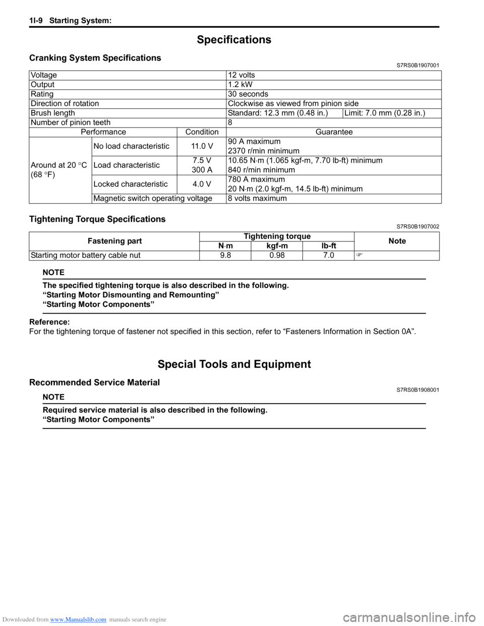
Cranking System SpecificationsS7RS0B1907001
Tightening Torque SpecificationsS7RS0B1907002
NOTE
The specified tightening torque is also described in the following.
“Starting Motor Dismounting and Remounting”
“Starting Motor Components”
Reference:
For the tightening torque of fastener not specified in this section, refer to “Fasteners Information in Section 0A”.
Special Tools and Equipment
Recommended Service MaterialS7RS0B1908001
NOTE
Required service material is also described in the following.
“Starting Motor Components”
Voltage 12 volts
Output 1.2 kW
Rating 30 seconds
Direction of rotation Clockwise as viewed from pinion side
Brush length Standard: 12.3 mm (0.48 in.) Limit: 7.0 mm (0.28 in.)
Number of pinion teeth 8
Performance Condition Guarantee
Around at 20 °C
(68 °F) No load characteristic 11.0 V
90 A maximum
2370 r/min minimum
Load characteristic 7.5 V
300 A 10.65 N
⋅m (1.065 kgf-m, 7.70 lb-ft) minimum
840 r/min minimum
Locked characteristic 4.0 V 780 A maximum
20 N
⋅m (2.0 kgf-m, 14.5 lb-ft) minimum
Magnetic switch operating voltage 8 volts maximum
Fastening part Tightening torque
Note
N ⋅mkgf-mlb-ft
Starting motor battery cable nut 9.8 0.98 7.0 �)
Page 416 of 1496
Downloaded from www.Manualslib.com manuals search engine 1J-6 Charging System:
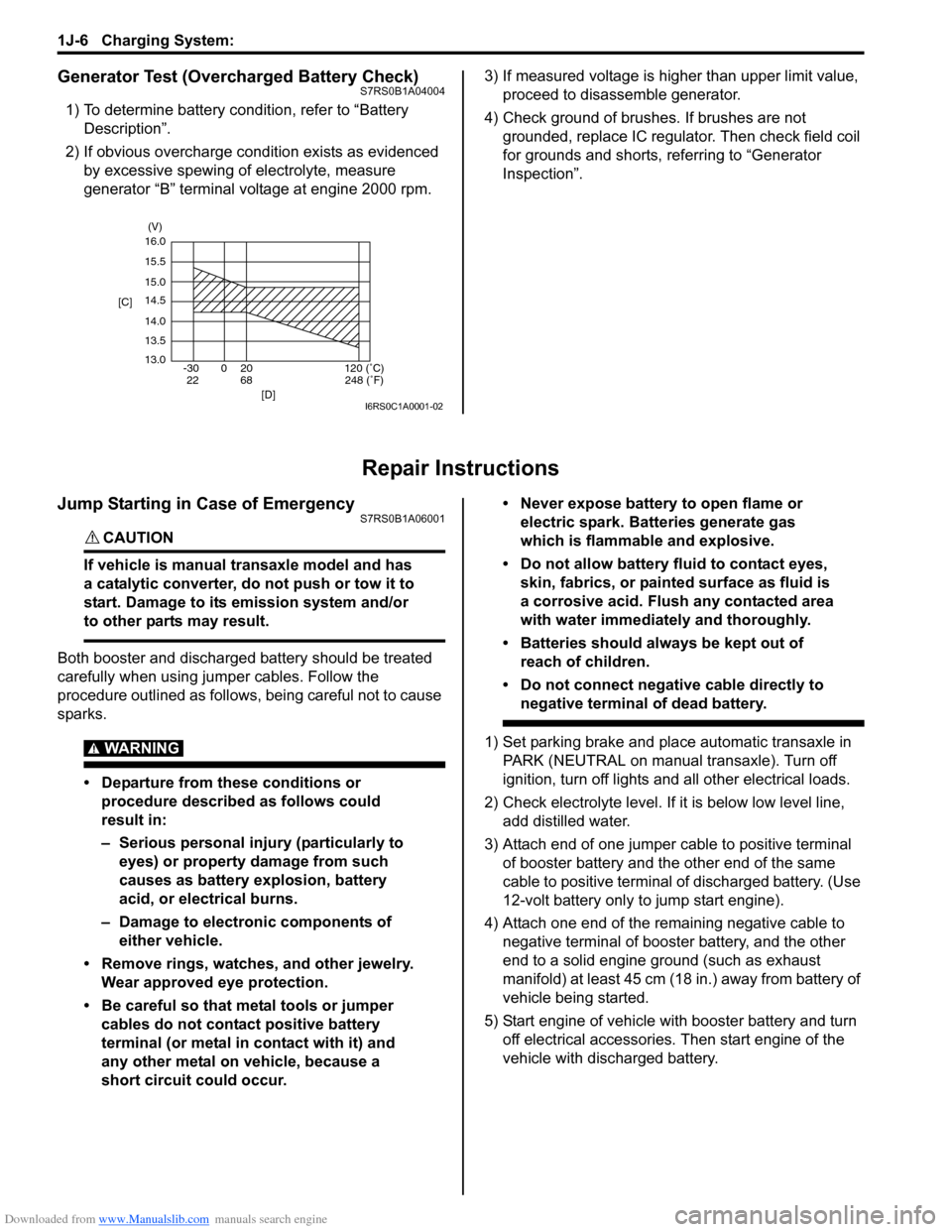
Generator Test (Overcharged Battery Check)S7RS0B1A04004
1) To determine battery condition, refer to “Battery Description”.
2) If obvious overcharge condition exists as evidenced by excessive spewing of electrolyte, measure
generator “B” terminal voltage at engine 2000 rpm. 3) If measured voltage is higher than upper limit value,
proceed to disassemble generator.
4) Check ground of brushes. If brushes are not grounded, replace IC regulator. Then check field coil
for grounds and shorts, referring to “Generator
Inspection”.
Repair Instructions
Jump Starting in Case of EmergencyS7RS0B1A06001
CAUTION!
If vehicle is manual transaxle model and has
a catalytic converter, do not push or tow it to
start. Damage to its emission system and/or
to other parts may result.
Both booster and discharged battery should be treated
carefully when using ju mper cables. Follow the
procedure outlined as follows, being careful not to cause
sparks.
WARNING!
• Departure from these conditions or procedure described as follows could
result in:
– Serious personal injury (particularly to eyes) or property damage from such
causes as battery explosion, battery
acid, or electrical burns.
– Damage to electronic components of either vehicle.
• Remove rings, watches, and other jewelry. Wear approved eye protection.
• Be careful so that metal tools or jumper cables do not contact positive battery
terminal (or metal in contact with it) and
any other metal on vehicle, because a
short circuit could occur. • Never expose battery to open flame or
electric spark. Batteries generate gas
which is flammable and explosive.
• Do not allow battery fluid to contact eyes, skin, fabrics, or painted surface as fluid is
a corrosive acid. Flush any contacted area
with water immediately and thoroughly.
• Batteries should always be kept out of reach of children.
• Do not connect negative cable directly to negative terminal of dead battery.
1) Set parking brake and place automatic transaxle in PARK (NEUTRAL on manual transaxle). Turn off
ignition, turn off lights and all other electrical loads.
2) Check electrolyte level. If it is below low level line, add distilled water.
3) Attach end of one jumper cable to positive terminal of booster battery and the other end of the same
cable to positive terminal of discharged battery. (Use
12-volt battery only to jump start engine).
4) Attach one end of the remaining negative cable to negative terminal of booster battery, and the other
end to a solid engine ground (such as exhaust
manifold) at least 45 cm (18 in.) away from battery of
vehicle being started.
5) Start engine of vehicle with booster battery and turn off electrical accessories. Then start engine of the
vehicle with discharged battery.
16.0
15.5
15.0
14.5
14.0
13.5
13.0 -30 0 20
[C]
[D]
68
22120 (˚C)
248 (˚F)
(V)
I6RS0C1A0001-02