2008 SUZUKI SWIFT diagnostic
[x] Cancel search: diagnosticPage 367 of 1496

Downloaded from www.Manualslib.com manuals search engine Engine Cooling System: 1F-4
Diagnostic Information and Procedures
Engine Cooling Symptom DiagnosisS7RS0B1604001
ConditionPossible cause Correction / Reference Item
Engine overheats
(Radiator fan operates) Loose or broken water pump belt
Adjust or replace.
Not enough coolant Check coolant level and add as necessary.
Faulty thermostat Replace.
Faulty water pump Replace.
Dirty or bent radiator fins Clean or remedy.
Coolant leakage on cooling system Repair.
Clogged radiator Check and replace radiator as necessary.
Faulty radiator cap Replace.
Improper ignition timing Adjust.
Dragging brakes Adjust brake.
Slipping clutch Adjust or replace.
Poor charge battery Check and replace as necessary.
Poor generation generator Check and repair.
ECT sensor faulty Check and replace as necessary.
Radiator cooling fan relay No.2 and/or
No.3 faulty Check and replace as necessary.
Radiator fan motor faulty Check and replace as necessary.
ECM faulty Check and replace as necessary.
Wiring or grounding faulty Repair as necessary.
Equipped with too much electric load
part(s) Dismount.
Engine overheats
(Radiator fan does not
operate) Fuse blown
Check 30 A fuse of relay/fuse box and check
for short circuit to ground.
Radiator cooling fan relay No.1 faulty Check and replace as necessary.
ECT sensor faulty Check and replace as necessary.
Radiator cooling fan motor faulty Check and replace as necessary.
Wiring or grounding faulty Repair as necessary.
ECM faulty Check and replace as necessary.
Page 377 of 1496

Downloaded from www.Manualslib.com manuals search engine Fuel System: 1G-2
Fuel Pump DescriptionS7RS0B1701003
The fuel pump (1) is an in-tank type electric pump.
Incorporated in the pump assembly are;
a fuel filter (2) and a fuel pressure regulator (3) are
included and a fuel level gauge (4) is attached.
Addition of the fuel pressure regulator to the fuel pump
makes it possible to mainta in the fuel pressure at
constant level and ECM controls compensation for
variation in the intake manifold pressure.
Schematic and Routing Diagram
Fuel Delivery System DiagramS7RS0B1702001
Diagnostic Information and Procedures
Fuel Pressure InspectionS7RS0B1704001
WARNING!
Before starting the following procedure, be
sure to observe “Precautions on Fuel System
Service” in order to reduce the risk or fire
and personal injury.
1) Relieve fuel pressure in fuel feed line referring to
“Fuel Pressure Relief Procedure”.
2) Disconnect fuel feed hose from fuel delivery pipe.
3) Connect special tools and hose between fuel feed hose (1) and fuel delivery pipe as shown in figure,
and clamp hoses securely in order to ensure that no
leaks occur during checking.
Special tool
(A): 09912–58442
(B): 09912–58432
(C): 09912–58490
1
3
2
4
I6RS0C170001-01
4
6 7
8
12
2 3
11
10
5
1
9
I6RS0C170002-01
1. Fuel tank
5. Fuel injector9. EVAP canister
2. Fuel pump 6. Fuel feed line10. Fuel filter
3. Fuel pressure regulator 7. Fuel vapor line 11. Main fuel level sensor
4. Delivery pipe 8. Intake manifold12. EVAP canister purge valve
1
(C) (B)
(A)
I3RM0A170004-01
Page 396 of 1496
Downloaded from www.Manualslib.com manuals search engine 1H-4 Ignition System:
Diagnostic Information and Procedures
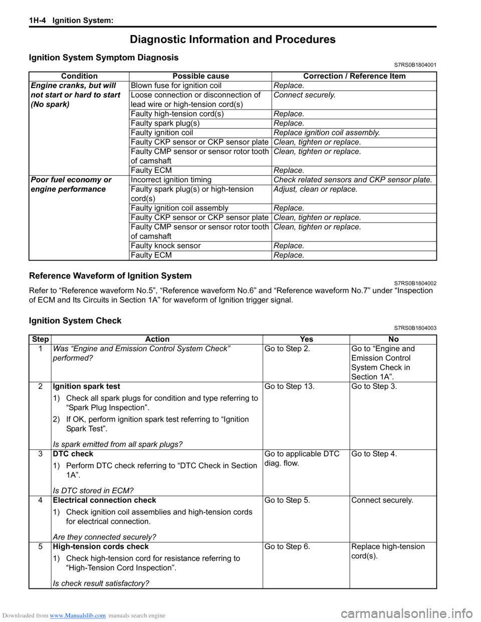
Ignition System Symptom DiagnosisS7RS0B1804001
Reference Waveform of Ignition SystemS7RS0B1804002
Refer to “Reference waveform No.5”, “Reference waveform No.6” and “Reference waveform No.7” under “Inspection
of ECM and Its Circuits in Section 1A” for waveform of Ignition trigger signal.
Ignition System CheckS7RS0B1804003
Condition Possible cause Correction / Reference Item
Engine cranks, but will
not start or hard to start
(No spark) Blown fuse for ignition coil
Replace.
Loose connection or disconnection of
lead wire or high-tension cord(s) Connect securely.
Faulty high-tension cord(s) Replace.
Faulty spark plug(s) Replace.
Faulty ignition coil Replace ignition coil assembly.
Faulty CKP sensor or CKP sensor plate Clean, tighten or replace.
Faulty CMP sensor or sensor rotor tooth
of camshaft Clean, tighten or replace.
Faulty ECM Replace.
Poor fuel economy or
engine performance Incorrect ignition timing
Check related sensors and CKP sensor plate.
Faulty spark plug(s) or high-tension
cord(s) Adjust, clean or replace.
Faulty ignition coil assembly Replace.
Faulty CKP sensor or CKP sensor plate Clean, tighten or replace.
Faulty CMP sensor or sensor rotor tooth
of camshaft Clean, tighten or replace.
Faulty knock sensor Replace.
Faulty ECM Replace.
StepAction YesNo
1 Was “Engine and Emission Control System Check”
performed? Go to Step 2.
Go to “Engine and
Emission Control
System Check in
Section 1A”.
2 Ignition spark test
1) Check all spark plugs for condition and type referring to
“Spark Plug Inspection”.
2) If OK, perform ignition spark test referring to “Ignition Spar k Tes t”.
Is spark emitted from all spark plugs? Go to Step 13. Go to Step 3.
3 DTC check
1) Perform DTC check referring to “DTC Check in Section
1A”.
Is DTC stored in ECM? Go to applicable DTC
diag. flow.
Go to Step 4.
4 Electrical connection check
1) Check ignition coil assemblies and high-tension cords
for electrical connection.
Are they connected securely? Go to Step 5.
Connect securely.
5 High-tension cords check
1) Check high-tension cord for resistance referring to
“High-Tension Cord Inspection”.
Is check result satisfactory? Go to Step 6.
Replace high-tension
cord(s).
Page 402 of 1496
Downloaded from www.Manualslib.com manuals search engine 1I-1 Starting System:
Engine
Starting System
Schematic and Routing Diagram
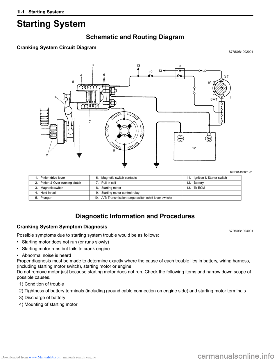
Cranking System Circuit DiagramS7RS0B1902001
Diagnostic Information and Procedures
Cranking System Symptom DiagnosisS7RS0B1904001
Possible symptoms due to starting system trouble would be as follows:
• Starting motor does not run (or runs slowly)
• Starting motor runs but fails to crank engine
• Abnormal noise is heard
Proper diagnosis must be made to determine exactly where the cause of each trouble lies in battery, wiring harness,
(including starting motor switch), starting motor or engine.
Do not remove motor just because starting motor does not run. Check the following items and narrow down scope of
possible causes.
1) Condition of trouble
2) Tightness of battery terminals (including ground cable connection on engine side) and starting motor terminals
3) Discharge of battery
4) Mounting of starting motor
I4RS0A190001-01
1. Pinion drive lever 6. Magnetic switch contacts 11. Ignition & Starter switch
2. Pinion & Over-running clutch 7. Pull-in coil 12. Battery
3. Magnetic switch 8. Starting motor 13. To ECM
4. Hold-in coil 9. Starting motor control relay
5. Plunger 10. A/T: Transmission range switch (shift lever switch)
Page 411 of 1496
Downloaded from www.Manualslib.com manuals search engine Charging System: 1J-1
Engine
Charging System
General Description
Battery DescriptionS7RS0B1A01001
The battery has three major functions in the electrical
system.
• It is a source of electrical energy for cranking the engine.
• It acts as a voltage stabilizer for the electrical system.
• It can, for a limited time, provide energy when the electrical load exceeds the output of the generator.
Carrier and Hold-Down
The battery carrier should be in good condition so that it
will support the battery securely and keep it level. Before
installing the battery, the ba ttery carrier and hold-down
clamp should be clean and free from corrosion and
make certain there are no parts in carrier.
To prevent the battery from shaking in its carrier, the
hold-down bolts should be tight enough but not over-
tightened.
Electrolyte Freezing
The freezing point of electrolyte depends on its specific
gravity. Since freezing may ruin a battery, it should be
protected against freezing by keeping it in a fully
charged condition. If a battery is frozen accidentally, it
should not be charged until it is warmed.
Sulfation
If the battery is allowed to stand for a long period in
discharged condition, the lead sulfate becomes
converted into a hard, cryst alline substance, which will
not easily turn back to the active material again during
the subsequent recharging. “Sulfation” means the result
as well as the process of that reaction. Such a battery
can be revived by very slow charging and may be
restored to usable condition but its capacity is lower than
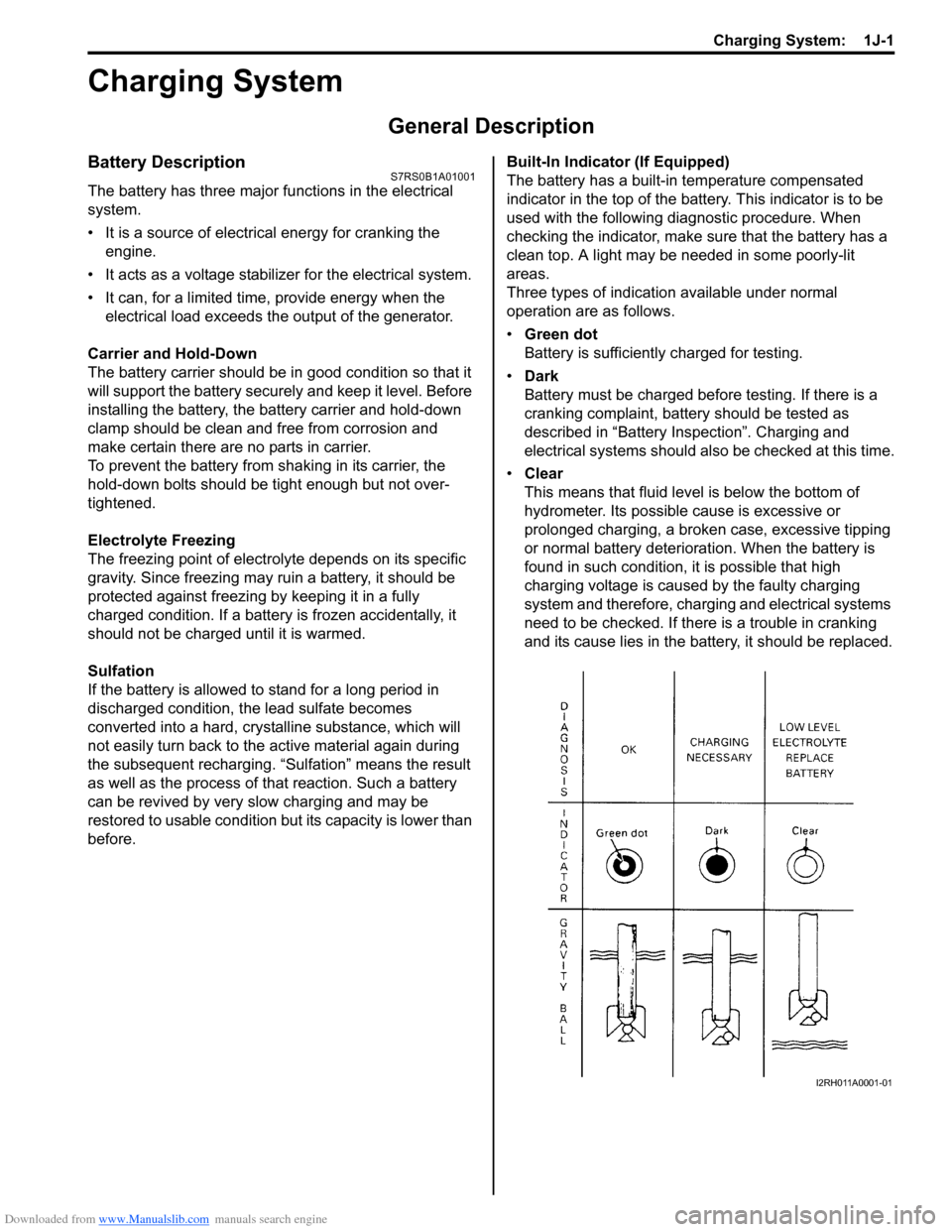
before. Built-In Indicator (If Equipped)
The battery has a built-in temperature compensated
indicator in the top of the battery. This indicator is to be
used with the following diagnostic procedure. When
checking the indicator, make sure that the battery has a
clean top. A light may be needed in some poorly-lit
areas.
Three types of indication available under normal
operation are as follows.
•
Green dot
Battery is sufficiently charged for testing.
• Dark
Battery must be charged before testing. If there is a
cranking complaint, battery should be tested as
described in “Battery Inspection”. Charging and
electrical systems should also be checked at this time.
• Clear
This means that fluid level is below the bottom of
hydrometer. Its possible cause is excessive or
prolonged charging, a broken case, excessive tipping
or normal battery deteriorat ion. When the battery is
found in such condition, it is possible that high
charging voltage is caused by the faulty charging
system and therefore, charging and electrical systems
need to be checked. If there is a trouble in cranking
and its cause lies in the battery, it should be replaced.
I2RH011A0001-01
Page 414 of 1496

Downloaded from www.Manualslib.com manuals search engine 1J-4 Charging System:
Diagnostic Information and Procedures
Battery InspectionS7RS0B1A04001
Common Causes of Failure
A battery is not designed to last indefinitely; however, with proper care, it will provide many years of service. If the
battery performs satisfactorily during te st but fails to operate properly for no apparent reason, the following are some
factors that may point to the cause of trouble:
• Accessories left on overnight or for an extended period without the generator operating.
• Slow average driving speeds for short periods.
• Electrical load exceeding generator output partic ularly with addition of aftermarket equipment.
• Defects in charging system such as high resistance, s lipping drive belt, loose generator output terminal, faulty
generator or voltage regulator, Refer to “Generator Symptom Diagnosis”.
• Battery abuse, including failure to keep battery cable terminals clean and tight or loose battery hold down.
• Mechanical problems in electrical sys tem such as shorted or pinched wires.
Visual Inspection
Check for obvious damage, such as cracked or broken case or cover, that could permit loss of electrolyte. If obvious
damage is noted, replace battery. Determine cause of damage and correct as needed.
Generator Symptom DiagnosisS7RS0B1A04002
CAUTION!
• Do not mistake polarities of “IG” terminal and “L” terminal.
• Do not create short circuit between “IG” and “L” terminals. Always connect these terminals through a lamp.
• Do not connect any load between “L” and “E” terminals.
• When connecting charger or booster battery to vehicle battery, refer to “Jump Starting in Case of Emergency”.
Trouble in charging system will show up as one or more of the following conditions:
1) Faulty indicator lamp operation.
2) An undercharged battery as evidenced by slow cranking or indicator dark.
3) An overcharged battery as evidenced by ex cessive spewing of electrolyte from vents.
Condition Possible cause Correction / Reference Item
Noisy generator Loose drive belt Adjust or replace drive belt.
Loose drive belt pulley Tighten by specified torque.
Loose mounting bolts Tighten by specified torque.
Worn or dirty bearings Replace.
Defective diode or stator Replace.
Charge light does not
light with ignition ON and
engine off Fuse blown
Replace fuse and check for shorted circuit.
Indicator lamp (LED) faulty Replace combination meter.
Wiring connection loose Tighten loose connection.
IC regulator or field coil faulty Replace.
Poor contact between brush and slip
ring Repair or replace.
Charge light does not go
out with engine running
(battery requires frequent
recharging) Drive belt loose or worn
Adjust or replace drive belt.
IC regulator or generator faulty Replace.
Wiring faulty Repair wiring.
Page 424 of 1496
Downloaded from www.Manualslib.com manuals search engine 1K-1 Exhaust System:
Engine
Exhaust System
General Description
Exhaust System DescriptionS7RS0B1B01001
The exhaust system consists of an exhaust manifold, three-way catalytic converter (TWC) in catalyst case, exhaust
pipes, a muffler and seals, gasket and etc.
The three-way catalytic converter is an emission control device added to the exhaust system to lower the levels of
Hydrocarbon (HC), Carbon Monoxide (CO), and Oxides of Nitrogen (NOx) pollutants in the exhaust gas.
Diagnostic Information and Procedures
Exhaust System CheckS7RS0B1B04001
WARNING!
To avoid the danger of being burned, do not touch the exhaust system when the system is hot. Any
service on the exhaust system should be performed when the system is cool.
At every interval of periodic maintenance service, and when vehicle is raised for other service, check exhaust system
as follows:
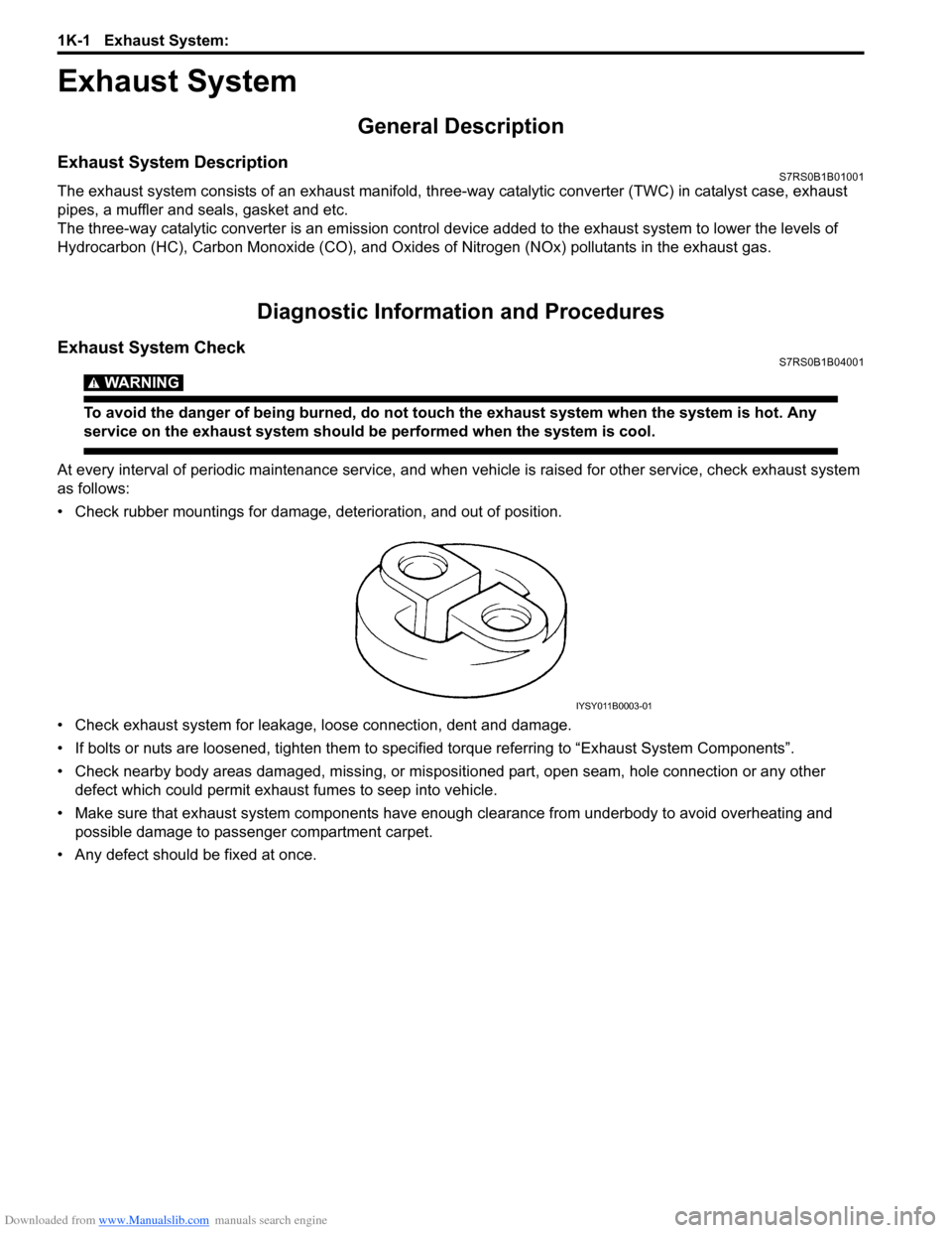
• Check rubber mountings for damage, deterioration, and out of position.
• Check exhaust system for leakage, loose connection, dent and damage.
• If bolts or nuts are loosened, tighten them to specified torque referring to “Exhaust System Components”.
• Check nearby body areas damaged, missing, or mispositio ned part, open seam, hole connection or any other
defect which could permit exhaust fumes to seep into vehicle.
• Make sure that exhaust system components have enough clearance from underbody to avoid overheating and
possible damage to passenger compartment carpet.
• Any defect should be fixed at once.
IYSY011B0003-01
Page 429 of 1496
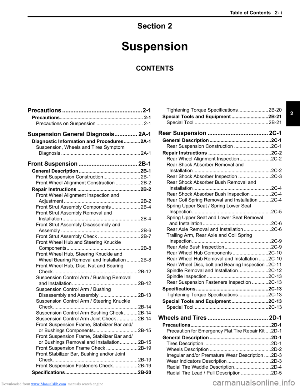
Downloaded from www.Manualslib.com manuals search engine Table of Contents 2- i
2
Section 2
CONTENTS
Suspension
Precautions ................................................. 2-1
Precautions............................................................. 2-1
Precautions on Suspension .................................. 2-1
Suspension General Dia gnosis.............. 2A-1
Diagnostic Information and Procedures ............ 2A-1
Suspension, Wheels and Tires Symptom Diagnosis .......................................................... 2A-1
Front Suspension ........... ......................... 2B-1
General Description ............................................. 2B-1
Front Suspension Construction ........................... 2B-1
Front Wheel Alignment Cons truction .................. 2B-2
Repair Instructions .............................................. 2B-2 Front Wheel Alignment Inspection and Adjustment ........................................................ 2B-2
Front Strut Assembly Comp onents ..................... 2B-4
Front Strut Assembly Removal and Installation ......................................................... 2B-4
Front Strut Assembly Disassembly and Assembly .......................................................... 2B-6
Front Strut Assembly Chec k ............................... 2B-7
Front Wheel Hub and Steering Knuckle Components...................................................... 2B-8
Front Wheel Hub, Steering Knuckle and Wheel Bearing Removal and Installation .......... 2B-8
Front Wheel Hub, Disc, Nut and Bearing Check .............................................................. 2B-12
Suspension Control Arm / Bushing Removal and Installation ................................................ 2B-12
Suspension Control Arm / Bushing Disassembly and Assembly ............................ 2B-13
Suspension Control Arm / Steering Knuckle Check .............................................................. 2B-14
Suspension Control Arm Bushing Check .......... 2B-14
Suspension Control Arm Joint Check ............... 2B-14
Front Suspension Fram e, Stabilizer Bar and/
or Bushings Components................................ 2B-15
Front Suspension Fram e, Stabilizer Bar and/
or Bushings Removal and Installation ............. 2B-15
Front Suspension Frame Ch eck ....................... 2B-19
Front Stabilizer Bar, Bushing and/or Joint Check .............................................................. 2B-19
Front Suspension Fastener s Check .................. 2B-19
Specifications ..................................................... 2B-20 Tightening Torque Specifications ...................... 2B-20
Special Tools and Equipmen t ...........................2B-21
Special Tool ...................................................... 2B-21
Rear Suspension ............ ......................... 2C-1
General Description .............................................2C-1
Rear Suspension Construction ...........................2C-1
Repair Instructions ........... ...................................2C-2
Rear Wheel Alignment Inspection .......................2C-2
Rear Shock Absorber Removal and Installation .........................................................2C-2
Rear Shock Absorber Ins pection ........................2C-3
Rear Shock Absorber Bush Removal and Installation .........................................................2C-4
Rear Shock Absorber Bush Inspection ...............2C-4
Rear Coil Spring Removal and Installation .........2C-4
Spring Upper Seat / Spring Lower Seat Inspection ..........................................................2C-5
Spring Upper Seat and Lower Seat Removal and Installation ..................................................2C-6
Rear Axle Removal and Inst allation ....................2C-6
Trailing Arm, Rear Axle and Coil Spring Inspection ..........................................................2C-9
Rear Axle Bush Inspection ..................................2C-9
Rear Wheel Hub Components ..........................2C-10
Rear Wheel Hub Removal an d Installation .......2C-10
Rear Wheel Disc, bolt and Bearing Inspection ..2C-11
Spindle Removal and Installation ......................2C-12
Spindle Inspection .............................................2C-13
Rear Suspension Fasteners Inspection ............2C-13
Specifications .................... .................................2C-13
Tightening Torque Specifications ......................2C-13
Special Tools and Equipmen t ...........................2C-13
Special Tool ......................................................2C-13
Wheels and Tires ............ ......................... 2D-1
Precautions...........................................................2D-1
Precaution for Emergency Flat Tire Repair Kit ....2D-1
General Description .............................................2D-1 Tires Description .................................................2D-1
Wheels Description .............................................2D-2
Irregular and/or Premature Wear Description .....2D-3
Wear Indicators Description ................................2D-3
Radial Tire Waddle Description...........................2D-4
Radial Tire Lead / Pull Description ......................2D-5