2008 SUZUKI SWIFT Transmission Fluid Pressure
[x] Cancel search: Transmission Fluid PressurePage 685 of 1496
Downloaded from www.Manualslib.com manuals search engine Automatic Transmission/Transaxle: 5A-41
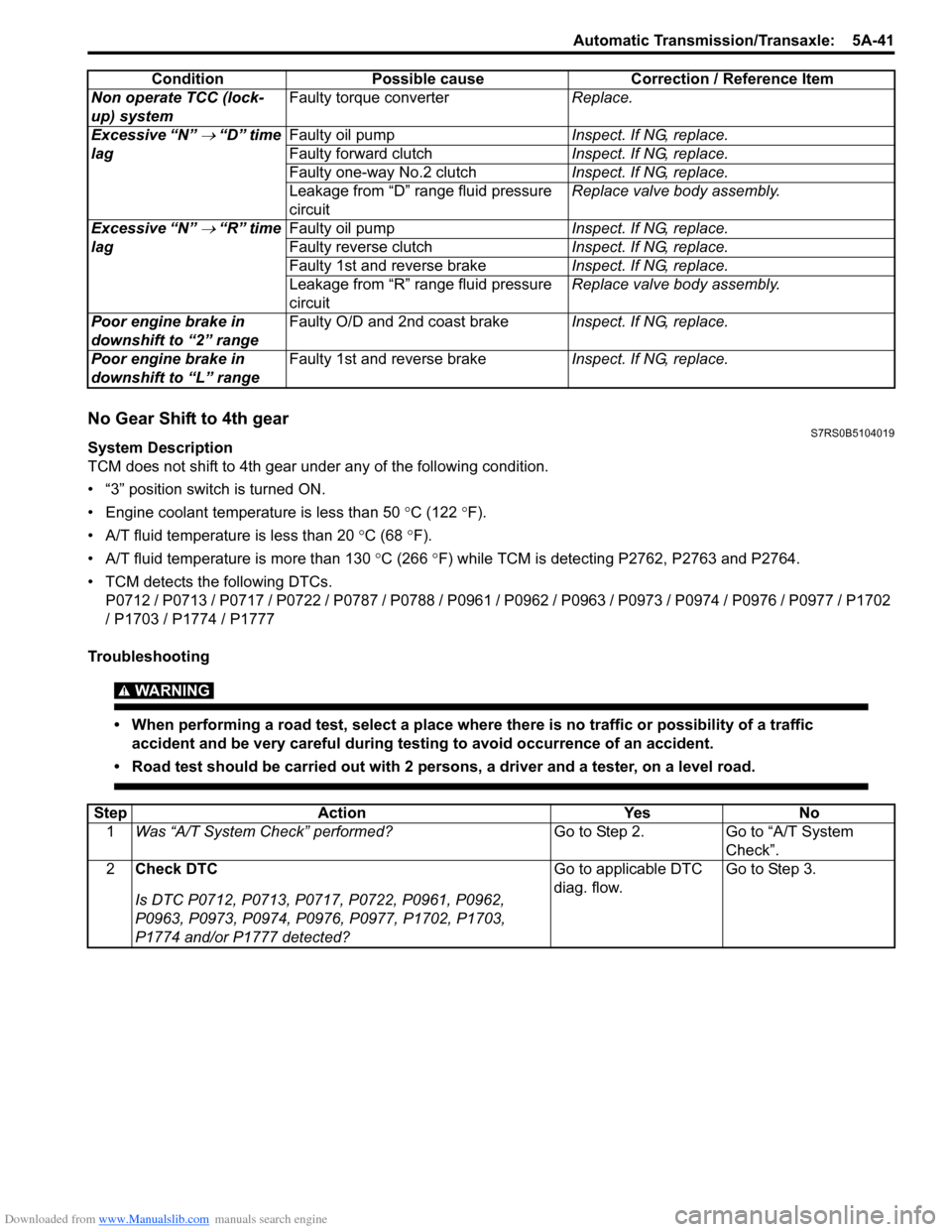
No Gear Shift to 4th gearS7RS0B5104019
System Description
TCM does not shift to 4th gear under any of the following condition.
• “3” position switch is turned ON.
• Engine coolant temperature is less than 50 °C (122 °F).
• A/T fluid temperature is less than 20 °C (68 °F).
• A/T fluid temperature is more than 130 °C (266 °F) while TCM is detecting P2762, P2763 and P2764.
• TCM detects the following DTCs. P0712 / P0713 / P0717 / P0722 / P0787 / P0788 / P0961 / P0962 / P0963 / P0973 / P0974 / P0976 / P0977 / P1702
/ P1703 / P1774 / P1777
Troubleshooting
WARNING!
• When performing a road test, select a place where there is no traffic or possibility of a traffic accident and be very careful during testing to avoid occurrence of an accident.
• Road test should be carried out with 2 persons, a driver and a tester, on a level road.
Non operate TCC (lock-
up) system Faulty torque converter
Replace.
Excessive “N”
→ “D” time
lag Faulty oil pump
Inspect. If NG, replace.
Faulty forward clutch Inspect. If NG, replace.
Faulty one-way No.2 clutch Inspect. If NG, replace.
Leakage from “D” range fluid pressure
circuit Replace valve body assembly.
Excessive “N”
→ “R” time
lag Faulty oil pump
Inspect. If NG, replace.
Faulty reverse clutch Inspect. If NG, replace.
Faulty 1st and reverse brake Inspect. If NG, replace.
Leakage from “R” range fluid pressure
circuit Replace valve body assembly.
Poor engine brake in
downshift to “2” range Faulty O/D and 2nd coast brake
Inspect. If NG, replace.
Poor engine brake in
downshift to “L” range Faulty 1st and reverse brake
Inspect. If NG, replace.
Condition Possible cause Correction / Reference Item
Step
Action YesNo
1 Was “A/T System Check” performed? Go to Step 2.Go to “A/T System
Check”.
2 Check DTC
Is DTC P0712, P0713, P0717, P0722, P0961, P0962,
P0963, P0973, P0974, P0976, P0977, P1702, P1703,
P1774 and/or P1777 detected? Go to applicable DTC
diag. flow.
Go to Step 3.
Page 727 of 1496

Downloaded from www.Manualslib.com manuals search engine Automatic Transmission/Transaxle: 5A-83
Connector “C34”Terminal Wire color Circuit Standard
voltage Condition
1 BLK Ground 0 – 1 V Ignition switch ON
2 LT GRN/
BLK Pressure control
solenoid valve (–)
0.6 – 1.0 V Ignition switch ON
3WHT/BLK TCC pressure control
solenoid valve (–) 0.6 – 1.0 V Ignition switch ON
4GRY Pressure control
solenoid valve (+) *0 – 0.6 V
↑↓
10 – 14 V
(“Reference waveform No. 1: ”) Engine running at idling.
(Output signal is duty pulse. Duty ratio varies
depending on throttle valve opening.)
5WHT/BLU TCC pressure control
solenoid valve (+) *0 – 0.6 V
↑↓
10 – 14 V
(“Reference waveform No. 2: ”) Engine running at idling.
(Output signal is duty pulse. Duty ratio varies
depending on torque converter clutch operating
condition.)
6 YEL/BLK Power source 10 – 14 V Ignition switch ON
7WHT CAN communication
line (Low) *2.5 – 3.6 V
↑↓
1.6 – 2.5 V
(“Reference waveform No. 3: ”) Engine running at idling with after warming up.
(CAN communication signal is pulse. Pulse signal
frequency varies depending on engine condition.))
8— — — —
9— — — —
10 — —— —
11 LT G R N Transmission fluid
temperature sensor (+) 2.9 – 3.1 V Ignition switch ON, fluid temperature is 20
°C (68 °F)
0.3 – 0.5 V Ignition switch ON, fluid temperature is 100 °C (212 °F)
12 ORN Transmission fluid
temperature sensor (–) 0 – 1 V Ignition switch ON
13 — —— —
14 BLU/BLK Timing solenoid valv e 0 – 1 V Ignition switch ON
15 BLK/YEL Shift solenoid valve-B
(No.2) 9 – 14 V Ignition switch ON, select lever in “P” range
16 BRN Shift solenoid valve-A
(No.1) 9 – 14 V Ignition switch ON, select lever in “P” range
17 RED CAN communication
line (High) *2.5 – 3.6 V
↑↓
1.6 – 2.5 V
(“Reference waveform No. 3: ”) Engine running at idling with after warming up.
(CAN communication signal is pulse. Pulse signal
frequency varies depending on engine condition.)
18 — —— —
19 — —— —
20 — —— —
21 — —— —
22 — —— —
23 BLK Ground 0 – 1 V Ignition switch ON
24 WHT/RED Power source
for back-
up 10 – 14 V Constantly
Page 743 of 1496
Downloaded from www.Manualslib.com manuals search engine Automatic Transmission/Transaxle: 5A-99
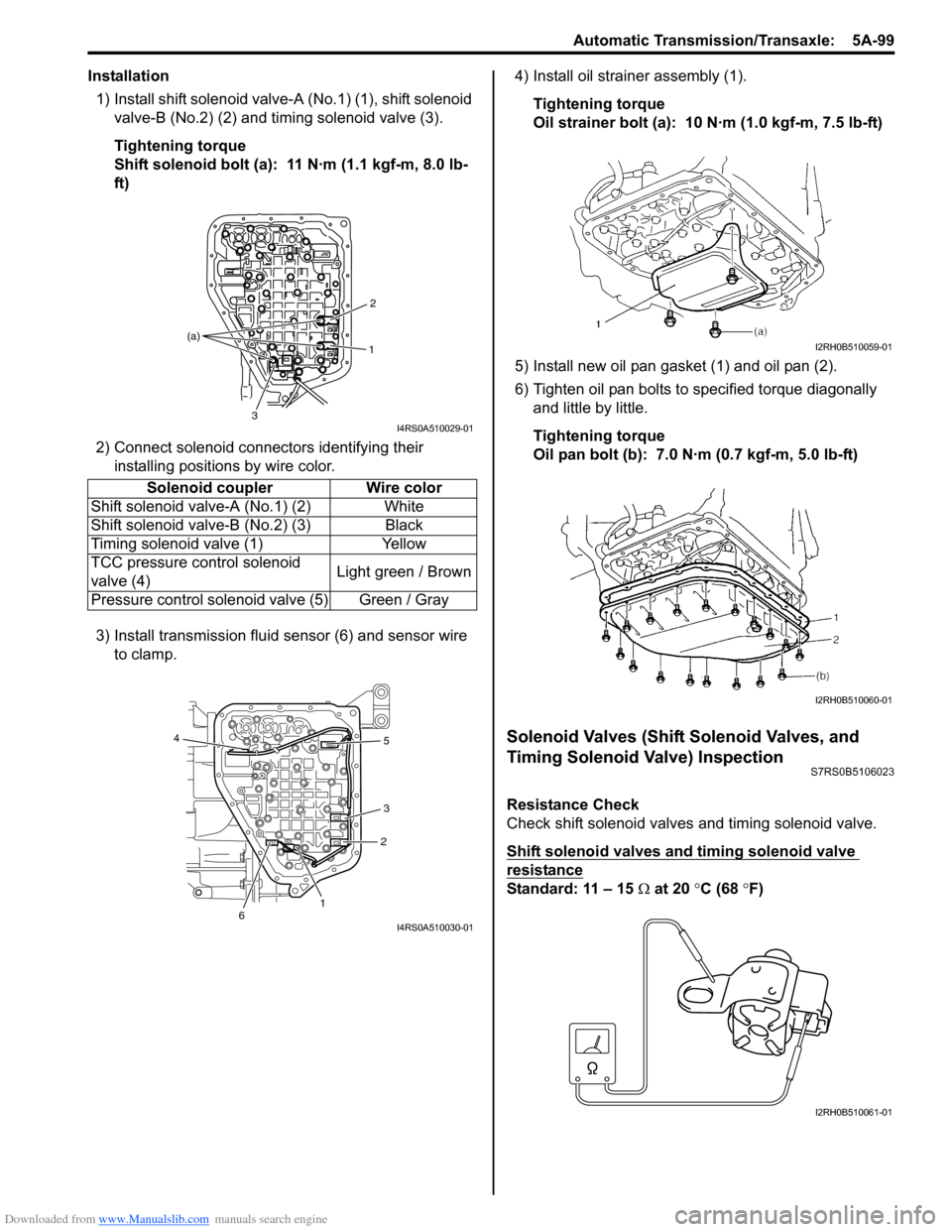
Installation1) Install shift solenoid valve- A (No.1) (1), shift solenoid
valve-B (No.2) (2) and timing solenoid valve (3).
Tightening torque
Shift solenoid bolt (a): 11 N·m (1.1 kgf-m, 8.0 lb-
ft)
2) Connect solenoid connectors identifying their installing positions by wire color.
3) Install transmission fluid sensor (6) and sensor wire to clamp. 4) Install oil strain
er assembly (1).
Tightening torque
Oil strainer bolt (a): 10 N·m (1.0 kgf-m, 7.5 lb-ft)
5) Install new oil pan gasket (1) and oil pan (2).
6) Tighten oil pan bolts to specified torque diagonally and little by little.
Tightening torque
Oil pan bolt (b): 7.0 N·m (0.7 kgf-m, 5.0 lb-ft)
Solenoid Valves (Shift Solenoid Valves, and
Timing Solenoid Valve) Inspection
S7RS0B5106023
Resistance Check
Check shift solenoid valves and timing solenoid valve.
Shift solenoid valves and timing solenoid valve
resistance
Standard: 11 – 15 Ω at 20 °C (68 ° F)
Solenoid coupler Wire color
Shift solenoid valv e-A (No.1) (2) White
Shift solenoid valv e-B (No.2) (3) Black
Timing solenoid valve (1) Yellow
TCC pressure control solenoid
valve (4) Light green / Brown
Pressure control solenoid valve (5) Green / Gray
1 2
3
(a)
I4RS0A510029-01
1
2
3 5
4
6
I4RS0A510030-01
I2RH0B510059-01
I2RH0B510060-01
I2RH0B510061-01
Page 745 of 1496
Downloaded from www.Manualslib.com manuals search engine Automatic Transmission/Transaxle: 5A-101
Pressure Control Solenoid Valves (Pressure
Control Solenoid and TCC Pressure Control
Solenoid) Removal and Installation
S7RS0B5106024
Removal1) Disconnect negative cable at battery.
2) Lift up vehicle.
3) Remove drain plug and drain A/T fluid.
4) Install drain plug.
Tightening torque
A/T fluid drain plug: 17 N·m (1.7 kgf-m, 12.5 lb-ft)
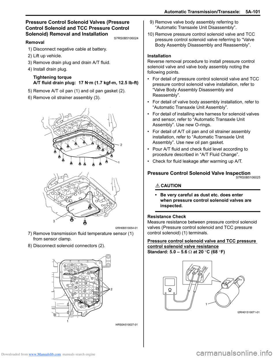
5) Remove A/T oil pan (1) and oil pan gasket (2).
6) Remove oil strain er assembly (3).
7) Remove transmission fluid temperature sensor (1) from sensor clamp.
8) Disconnect solenoid connectors (2). 9) Remove valve body assembly referring to
“Automatic Transaxl e Unit Disassembly”.
10) Remove pressure control solenoid valve and TCC pressure control solenoid valve referring to “Valve
Body Assembly Disassembly and Reassembly”.
Installation
Reverse removal procedure to install pressure control
solenoid valve and valve body assembly noting the
following points.
• For detail of pressure control solenoid valve and TCC pressure control solenoid va lve installation, refer to
“Valve Body Assembly Disassembly and
Reassembly”.
• For detail of valve body asse mbly installation, refer to
“Automatic Transaxle Unit Assembly”.
• For detail of installing wire harness for solenoid valves and sensor, refer to “Automatic Transaxle Unit
Assembly”. Use new O-rings.
• For detail of A/T oil pan and oil strainer assembly
installation, refer to “A utomatic Transaxle Unit
Assembly”. Use new oil pan gasket.
• Pour A/T fluid and check fluid level according to procedure described in “A/T Fluid Change”.
• Check for fluid leakage after warming up A/T.
Pressure Control Solenoid Valve InspectionS7RS0B5106025
CAUTION!
• Be very careful as dust etc. does enter when pressure control solenoid valves are
inspected.
Resistance Check
Measure resistance between pressure control solenoid
valves (Pressure control solenoid and TCC pressure
control solenoid) (1) terminals.
Pressure control solenoid valve and TCC pressure
control solenoid valve resistance
Standard: 5.0 – 5.6 Ω at 20 °C (68 °F)
I2RH0B510054-01
1 2I4RS0A510027-01
1
I2RH01510071-01
Page 756 of 1496
Downloaded from www.Manualslib.com manuals search engine 5A-112 Automatic Transmission/Transaxle:
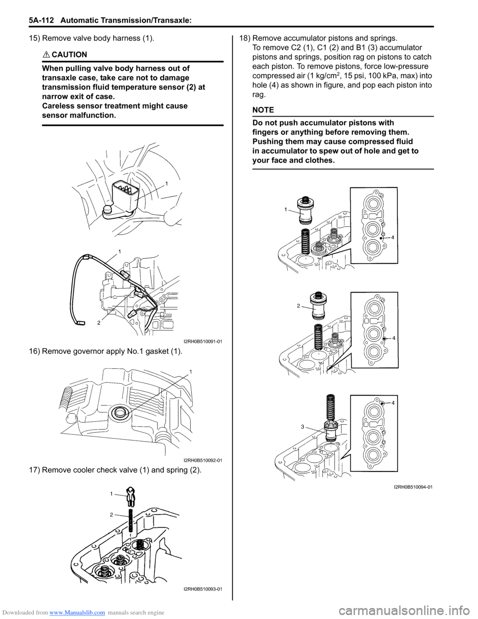
15) Remove valve body harness (1).
CAUTION!
When pulling valve body harness out of
transaxle case, take care not to damage
transmission fluid temperature sensor (2) at
narrow exit of case.
Careless sensor treatment might cause
sensor malfunction.
16) Remove governor apply No.1 gasket (1).
17) Remove cooler check valve (1) and spring (2).18) Remove accumulator pistons and springs.
To remove C2 (1), C1 (2) and B1 (3) accumulator
pistons and springs, position rag on pistons to catch
each piston. To remove pistons, force low-pressure
compressed air (1 kg/cm
2, 15 psi, 100 kPa, max) into
hole (4) as shown in figure, and pop each piston into
rag.
NOTE
Do not push accumulator pistons with
fingers or anything before removing them.
Pushing them may cause compressed fluid
in accumulator to spew out of hole and get to
your face and clothes.
I2RH0B510091-01
I2RH0B510092-01
I2RH0B510093-01
I2RH0B510094-01
Page 771 of 1496

Downloaded from www.Manualslib.com manuals search engine Automatic Transmission/Transaxle: 5A-127
Direct Clutch Assembly InspectionS7RS0B5106040
Clutch Discs, Plates and Retaining Plate
Check that sliding surfaces of discs, separator plates
and retaining plate are not worn hard or burnt. If
necessary, replace.
NOTE
• If disc lining is exfoliated, discolored, replace all discs.
• Before assembling new discs, soak them in A/T fluid for at least two hours.
Direct Clutch Return Spring Subassembly
Measure free length of direct clutch return spring.
Direct clutch return spring free length
“a”: 36.04 mm (1.419 in.)
NOTE
Do not apply excessive force when
measuring spring free length. Perform
measurement at several points.
Direct Clutch Piston
Shake direct clutch piston lightly and check that check
ball (1) is not stuck.
Blow in low pressure air (Max. 100 kPa, 1 kg/cm
2, 15 psi)
to check ball to check that there is no leakage.
I2RH0B510172-01
I2RH0B510173-01
I2RH0B510174-01
Page 783 of 1496

Downloaded from www.Manualslib.com manuals search engine Automatic Transmission/Transaxle: 5A-139
2) Install reduction driven gear (1) with special tools and hydraulic press.
Special tool
(A): 09913–84510
(B): 09925–88210 3) Install countershaft LH bearing (1) with special tools
and hydraulic press.
Special tool
(A): 09913–84510
(B): 09925–88210
Valve Body Assembly ComponentsS7RS0B5106052
I2RH0B510213-01
I2RH0B510214-01
I4RS0A510044-01
1. Pressure control solenoid valve 6. Temperature sensor clamp : Apply automatic transaxle fluid.
2. Shift solenoid valve-A (No.1) 7. Valve body assembly: 11 N⋅m (1.1 kgf-m, 8.0 lb-ft)
3. Shift solenoid valve-B (No.2) 8. Manual valve: Do not reuse.
4. TCC pressure control solenoid valve 9. Solenoid lock plate
5. Timing solenoid valve 10. O-ring
Page 808 of 1496
Downloaded from www.Manualslib.com manuals search engine 5A-164 Automatic Transmission/Transaxle:
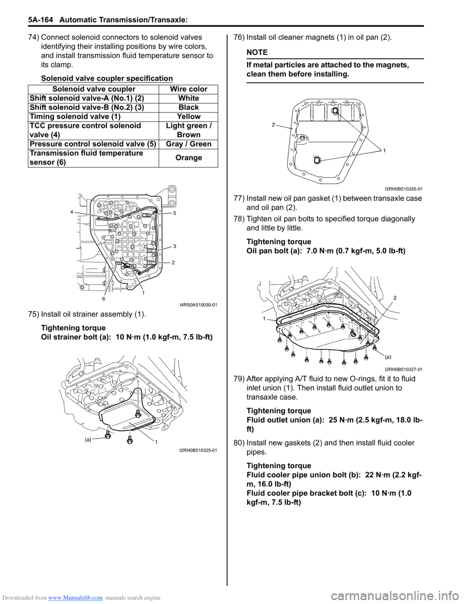
74) Connect solenoid connectors to solenoid valves identifying their installing positions by wire colors,
and install transmission fluid temperature sensor to
its clamp.
Solenoid valve coupler specification
75) Install oil strainer assembly (1).
Tightening torque
Oil strainer bolt (a): 10 N·m (1.0 kgf-m, 7.5 lb-ft) 76) Install oil cleaner magnets (1) in oil pan (2).
NOTE
If metal particles are attached to the magnets,
clean them before installing.
77) Install new oil pan gasket (1) between transaxle case
and oil pan (2).
78) Tighten oil pan bolts to specified torque diagonally and little by little.
Tightening torque
Oil pan bolt (a): 7.0 N·m (0.7 kgf-m, 5.0 lb-ft)
79) After applying A/T fluid to new O-rings, fit it to fluid inlet union (1). Then inst all fluid outlet union to
transaxle case.
Tightening torque
Fluid outlet union (a): 25 N·m (2.5 kgf-m, 18.0 lb-
ft)
80) Install new gaskets (2) and then install fluid cooler pipes.
Tightening torque
Fluid cooler pipe union bolt (b): 22 N·m (2.2 kgf-
m, 16.0 lb-ft)
Fluid cooler pipe bracket bolt (c): 10 N·m (1.0
kgf-m, 7.5 lb-ft)
Solenoid valve coupler Wire color
Shift solenoid valve-A (No.1) (2) White
Shift solenoid val ve-B (No.2) (3) Black
Timing solenoid valve (1) Yellow
TCC pressure control solenoid
valve (4) Light green /
Brown
Pressure control solenoid valve (5) Gray / Green
Transmission fluid temperature
sensor (6) Orange
12
3 5
4
6
I4RS0A510030-01
I2RH0B510325-01
I2RH0B510326-01
I2RH0B510327-01