Page 754 of 1496
Downloaded from www.Manualslib.com manuals search engine 5A-110 Automatic Transmission/Transaxle:
Automatic Transaxle Unit DisassemblyS7RS0B5106033
CAUTION!
• Thoroughly clean transaxle exterior before overhauling it.
• Keep working table, tools and hands clean while overhauling.
• Use special care to handle aluminum parts so as not to damage them.
• Do not expose removed parts to dust. Keep them always clean.
1) Remove torque converter (1).
CAUTION!
Remove torque converte r as much straight
as possible. Leaning it may cause to damage
oil seal lip.
2) Remove engine mounting LH bracket (1).
3) Remove manual select lever (1). 4) Uncaulk lock washer (1),
then remove lock nut (2)
and lock washer.
5) Remove transmission range sensor (1).
6) Remove output shaft speed sensor (2) and input shaft speed sensor (1).
7) Remove harness bracket (3) and select cable clamp (4).
I2RH0B510078-01
I3RM0B510054-01
1
I3RM0B510055-01
1
2
I3RM0B510056-01
I3RM0B510057-01
I3RM0B510058-01
Page 757 of 1496
Downloaded from www.Manualslib.com manuals search engine Automatic Transmission/Transaxle: 5A-113
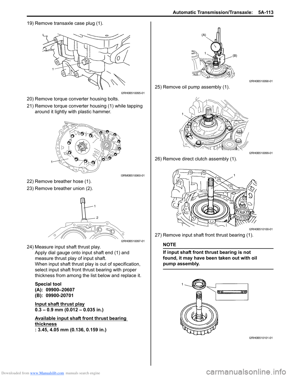
19) Remove transaxle case plug (1).
20) Remove torque converter housing bolts.
21) Remove torque converter housing (1) while tapping
around it lightly with plastic hammer.
22) Remove breather hose (1).
23) Remove breather union (2).
24) Measure input shaft thrust play. Apply dial gauge onto input shaft end (1) and
measure thrust play of input shaft.
When input shaft thrust play is out of specification,
select input shaft front th rust bearing with proper
thickness from among the list below and replace it.
Special tool
(A): 09900–20607
(B): 09900-20701
Input shaft thrust play
0.3 – 0.9 mm (0.012 – 0.035 in.)
Available input shaft front thrust bearing
thickness
: 3.45, 4.05 mm (0.136, 0.159 in.) 25) Remove oil pump assembly (1).
26) Remove direct clutch assembly (1).
27) Remove input shaft front thrust bearing (1).
NOTE
If input shaft front thrust bearing is not
found, it may have been taken out with oil
pump assembly.
I2RH0B510095-01
I3RM0B510060-01
1
2
I2RH0B510097-01
I2RH0B510098-01
I2RH0B510099-01
I2RH0B510100-01
I2RH0B510101-01
Page 766 of 1496
Downloaded from www.Manualslib.com manuals search engine 5A-122 Automatic Transmission/Transaxle:
Oil Pump Assembly Disassembly and
Reassembly
S7RS0B5106035
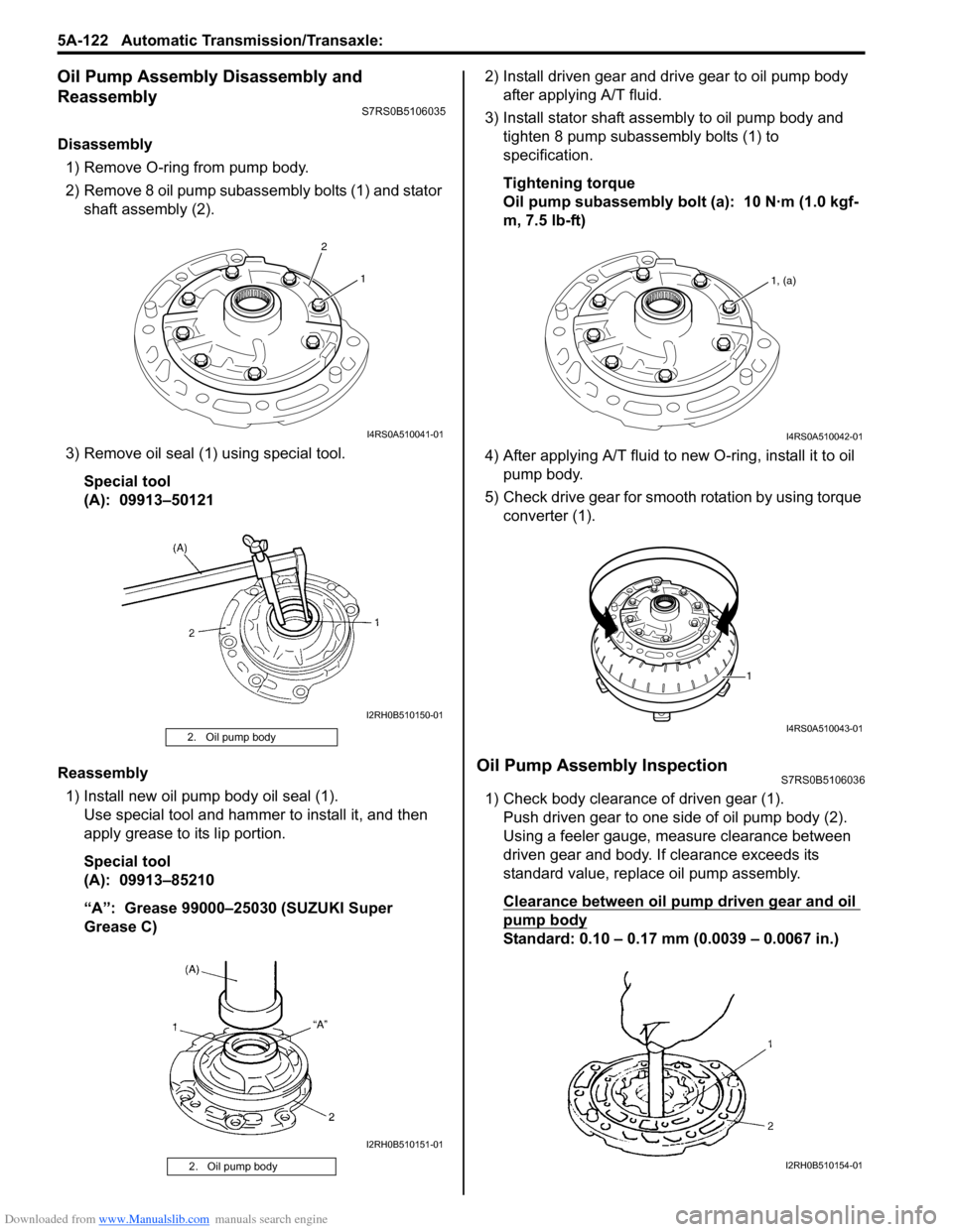
Disassembly1) Remove O-ring from pump body.
2) Remove 8 oil pump subassembly bolts (1) and stator shaft assembly (2).
3) Remove oil seal (1) using special tool. Special tool
(A): 09913–50121
Reassembly 1) Install new oil pump body oil seal (1). Use special tool and hammer to install it, and then
apply grease to its lip portion.
Special tool
(A): 09913–85210
“A”: Grease 99000–25030 (SUZUKI Super
Grease C) 2) Install driven gear and drive gear to oil pump body
after applying A/T fluid.
3) Install stator shaft assembly to oil pump body and tighten 8 pump subassembly bolts (1) to
specification.
Tightening torque
Oil pump subassembly bolt (a): 10 N·m (1.0 kgf-
m, 7.5 lb-ft)
4) After applying A/T fluid to new O-ring, install it to oil pump body.
5) Check drive gear for smooth rotation by using torque converter (1).
Oil Pump Assembly InspectionS7RS0B5106036
1) Check body clearance of driven gear (1).Push driven gear to one side of oil pump body (2).
Using a feeler gauge, m easure clearance between
driven gear and body. If clearance exceeds its
standard value, replace oil pump assembly.
Clearance between oil pump driven gear and oil
pump body
Standard: 0.10 – 0.17 mm (0.0039 – 0.0067 in.)
2. Oil pump body
2. Oil pump body
2 1
I4RS0A510041-01
I2RH0B510150-01
I2RH0B510151-01
1, (a)
I4RS0A510042-01
1
I4RS0A510043-01
I2RH0B510154-01
Page 767 of 1496

Downloaded from www.Manualslib.com manuals search engine Automatic Transmission/Transaxle: 5A-123
2) Check tip clearance of both drive and driven gears.Using a feeler gauge, m easure clearance between
drive and driven gear tips. If clearance exceeds its
standard value, replace oil pump assembly.
Tip clearance between oil pump drive gear and
oil pump driven gear
Standard: 0.07 – 0.15 mm (0.0028 – 0.0059 in.)
3) Check side clearance of both gears. Using a straightedge (1) and a feeler gauge (2),
measure side clearance between gears and pump
body.
If clearance exceeds its standard value, replace oil
pump assembly.
Side clearance between gears and oil pump body
Standard: 0.02 – 0.05 mm (0.0008 – 0.0019 in.)
4) Using special tool, measure stator shaft bush (1) bore.
If measured stator shaft bush bore is out of
specifications, replace oil pump assembly with new
one.
Special tool
(A): 09900–20605
Stator shaft bush bore
Standard: 18.424 – 18.450 mm (0.7254 – 0.7264
in.) 5) Install direct clutch asse
mbly (1) to stator shaft
assembly (2), then ensure that direct clutch
assembly turns smoothly.
If unsmooth rotation or noise are found in oil pump
assembly, replace oil pump assembly with new one.
This check should also be done to input shaft
assembly and replace input shaft assembly if
necessary.
6) Using special tool, measure oil pump body bush bore.
If measured oil pump body bush (1) bore is out of
specifications, replace o il pump assembly with new
one. Torque converter also needs to be checked.
Replace torque converter, if necessary.
Special tool
(A): 09900–20605
Oil pump body bush bore
Standard: 38.113 – 38.138 mm (1.5005 – 1.5015
in.)
I2RH0B510155-01
I2RH0B510156-01
I2RH0B510157-01
I2RH0B510158-01
I2RH0B510159-01
Page 788 of 1496
Downloaded from www.Manualslib.com manuals search engine 5A-144 Automatic Transmission/Transaxle:
Torque Converter Housing Disassembly and
Reassembly
S7RS0B5106057
Disassembly1) Remove fluid reservoir RH plate (1) and lubrication tube clamp (2).
2) Remove lubrication LH tube (1) and RH tube (2).
NOTE
Do not bend lubrication tube with excessive
force.
3) Remove differential side oil seal (1). 4) Remove countershaft RH bearing cup by using
special tools.
Special tool
(A): 09944–96011
(B): 09942–15511
5) Remove differential side RH bearing cup by using special tools.
Special tool
(A): 09944–96011
(B): 09942–15511
6) Remove torque converter case plugs (1).
I2RH0B510236-01
I2RH0B510237-01
I2RH0B510238-01
I2RH0B510239-01
I2RH0B510240-01
I2RH0B510241-01
Page 789 of 1496
Downloaded from www.Manualslib.com manuals search engine Automatic Transmission/Transaxle: 5A-145
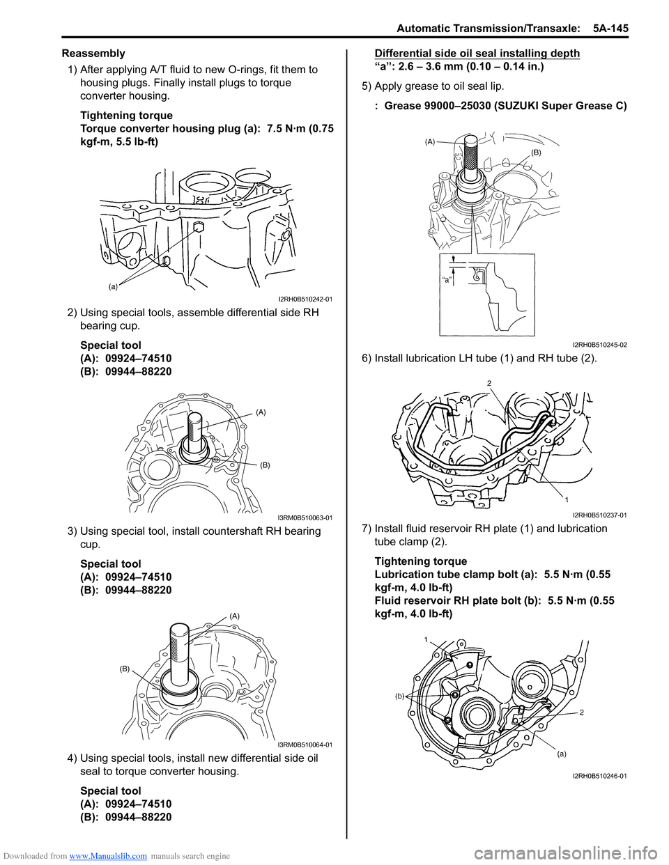
Reassembly1) After applying A/T fluid to new O-rings, fit them to housing plugs. Finally install plugs to torque
converter housing.
Tightening torque
Torque converter housing plug (a): 7.5 N·m (0.75
kgf-m, 5.5 lb-ft)
2) Using special tools, assemble differential side RH bearing cup.
Special tool
(A): 09924–74510
(B): 09944–88220
3) Using special tool, install countershaft RH bearing cup.
Special tool
(A): 09924–74510
(B): 09944–88220
4) Using special tools, install new differential side oil seal to torque converter housing.
Special tool
(A): 09924–74510
(B): 09944–88220 Differential side oil seal installing depth
“a”: 2.6 – 3.6 mm (0.10 – 0.14 in.)
5) Apply grease to oil seal lip. : Grease 99000–25030 (SUZUKI Super Grease C)
6) Install lubrication LH tube (1) and RH tube (2).
7) Install fluid reservoir RH plate (1) and lubrication tube clamp (2).
Tightening torque
Lubrication tube clamp bolt (a): 5.5 N·m (0.55
kgf-m, 4.0 lb-ft)
Fluid reservoir RH plate bolt (b): 5.5 N·m (0.55
kgf-m, 4.0 lb-ft)
I2RH0B510242-01
(A)
(B)
I3RM0B510063-01
(B) (A)
I3RM0B510064-01
I2RH0B510245-02
I2RH0B510237-01
I2RH0B510246-01
Page 792 of 1496
Downloaded from www.Manualslib.com manuals search engine 5A-148 Automatic Transmission/Transaxle:
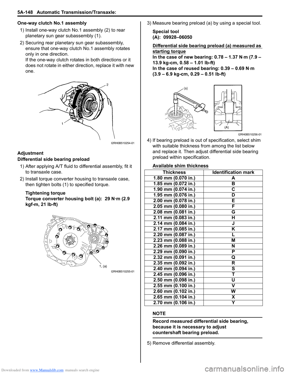
One-way clutch No.1 assembly1) Install one-way clutch No.1 assembly (2) to rear planetary sun gear subassembly (1).
2) Securing rear planetary sun gear subassembly, ensure that one-way clutch No.1 assembly rotates
only in one direction.
If the one-way clutch rotates in both directions or it
does not rotate in either direction, replace it with new
one.
Adjustment
Differential side bearing preload 1) After applying A/T fluid to differential assembly, fit it to transaxle case.
2) Install torque converter housing to transaxle case, then tighten bolts (1) to specified torque.
Tightening torque
Torque converter housing bolt (a): 29 N·m (2.9
kgf-m, 21 lb-ft) 3) Measure bearing preload (a) by using a special tool.
Special tool
(A): 09928–06050
Differential side bearing preload (a) measured as
starting torque
In the case of new bearing: 0.78 – 1.37 N ⋅m (7.9 –
13.9 kg-cm, 0.58 – 1.01 lb-ft)
In the case of reused bearing: 0.39 – 0.69 N ⋅m
(3.9 – 6.9 kg-cm, 0.29 – 0.51 lb-ft)
4) If bearing preload is out of specification, select shim with suitable thickness from among the list below
and replace it. Then adjust differential side bearing
preload within specification.
Available shim thickness
NOTE
Record measured differential side bearing,
because it is necessary to adjust
countershaft bearing preload.
5) Remove differential assembly.
I2RH0B510254-01
I2RH0B510255-01
Thickness Identification mark
1.80 mm (0.070 in.) A
1.85 mm (0.072 in.) B
1.90 mm (0.074 in.) C
1.95 mm (0.076 in.) D
2.00 mm (0.078 in.) E
2.05 mm (0.080 in.) F
2.08 mm (0.081 in.) G
2.11 mm (0.083 in.) H
2.14 mm (0.084 in.) J
2.17 mm (0.085 in.) K
2.20 mm (0.087 in.) L
2.23 mm (0.088 in.) M
2.26 mm (0.089 in.) N
2.29 mm (0.090 in.) P
2.32 mm (0.091 in.) Q
2.35 mm (0.092 in.) R
2.40 mm (0.094 in.) S
2.45 mm (0.096 in.) T
2.50 mm (0.098 in.) U
2.55 mm (0.100 in.) V
2.60 mm (0.102 in.) W
2.65 mm (0.104 in.) X
2.70 mm (0.106 in.) Y
I2RH0B510256-01
Page 793 of 1496
Downloaded from www.Manualslib.com manuals search engine Automatic Transmission/Transaxle: 5A-149
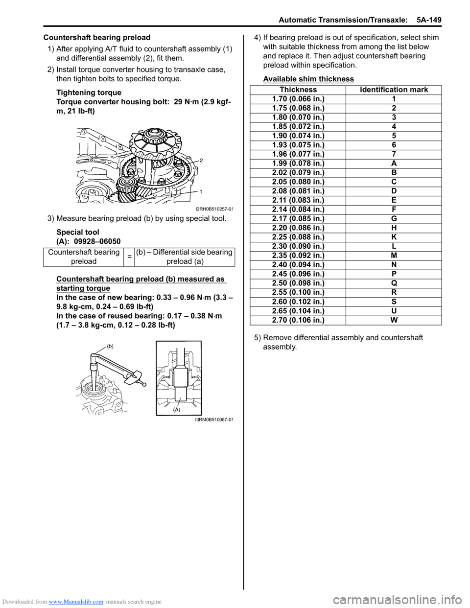
Countershaft bearing preload1) After applying A/T fluid to countershaft assembly (1) and differential assembly (2), fit them.
2) Install torque converter housing to transaxle case, then tighten bolts to specified torque.
Tightening torque
Torque converter housing bolt: 29 N·m (2.9 kgf-
m, 21 lb-ft)
3) Measure bearing preload (b) by using special tool. Special tool
(A): 09928–06050
Countershaft bearing preload (b) measured as
starting torque
In the case of new bearing: 0.33 – 0.96 N⋅ m (3.3 –
9.8 kg-cm, 0.24 – 0.69 lb-ft)
In the case of reused bearing: 0.17 – 0.38 N ⋅m
(1.7 – 3.8 kg-cm, 0.12 – 0.28 lb-ft) 4) If bearing preload is out of specification, select shim
with suitable thickness from among the list below
and replace it. Then adjust countershaft bearing
preload within specification.
Available shim thickness
5) Remove differential assembly and countershaft assembly.
Countershaft bearing
preload =(b) – Differential side bearing
preload (a)
I2RH0B510257-01
I3RM0B510067-01
Thickness Identification mark
1.70 (0.066 in.) 1
1.75 (0.068 in.) 2
1.80 (0.070 in.) 3
1.85 (0.072 in.) 4
1.90 (0.074 in.) 5
1.93 (0.075 in.) 6
1.96 (0.077 in.) 7
1.99 (0.078 in.) A
2.02 (0.079 in.) B
2.05 (0.080 in.) C
2.08 (0.081 in.) D
2.11 (0.083 in.) E
2.14 (0.084 in.) F
2.17 (0.085 in.) G
2.20 (0.086 in.) H
2.25 (0.088 in.) K
2.30 (0.090 in.) L
2.35 (0.092 in.) M
2.40 (0.094 in.) N
2.45 (0.096 in.) P
2.50 (0.098 in.) Q
2.55 (0.100 in.) R
2.60 (0.102 in.) S
2.65 (0.104 in.) U
2.70 (0.106 in.) W