Page 722 of 1496

Downloaded from www.Manualslib.com manuals search engine 5A-78 Automatic Transmission/Transaxle:
DTC P2763: Torque Converter Clutch Pressure Control Solenoid Control Circuit HighS7RS0B5104043
Wiring Diagram
DTC Detecting Condition and Trouble Area
DTC Confirmation Procedure
WARNING!
• When performing a road test, select a place where there is no traffic or possibility of a traffic
accident and be very careful during testing to avoid occurrence of an accident.
• Road test should be carried out with 2 persons, a driver and a tester, on a level road.
1) Connect scan tool to DLC with ig nition switch OFF, if available.
2) Clear DTC in TCM memory.
3) Start engine.
4) Keep engine running at idle speed in “P” range for 10 seconds or more.
5) Check DTC.
DTC Troubleshooting
1. TCM 3. A/T
2. TCC lock-up pressure control solenoid valve [A]: Terminal arrangement of TCM connector (viewed from harness side)
DTC detecting conditionTrouble area
Voltage of TCC lock-up pressure control solenoid valve TCM
terminal is high although TCM is commanding TCC lock-up
pressure control sole noid to turn OFF. • TCC lock-up pressure contro
l solenoid valve circuit
shorted to ground
• Malfunction of TCC lock-up pressure control solenoid valve
•TCM
12V
C34-5
C34-3
WHT/BLU
WHT/BLK
3
1
2
53
C34C35
[A]
I4RS0A510019-01
Step
Action YesNo
1 Was “A/T System Check” performed? Go to Step 2.Go to “A/T System
Check”.
Page 724 of 1496

Downloaded from www.Manualslib.com manuals search engine 5A-80 Automatic Transmission/Transaxle:
DTC P2764: Torque Converter Clutch Circuit Pressure Control Solenoid Control Circuit LowS7RS0B5104044
Wiring Diagram
DTC Detecting Condition and Trouble Area
DTC Confirmation Procedure
WARNING!
• When performing a road test, select a place where there is no traffic or possibility of a traffic
accident and be very careful during testing to avoid occurrence of an accident.
• Road test should be carried out with 2 persons, a driver and a tester, on a level road.
1) Connect scan tool to DLC with ig nition switch OFF, if available.
2) Clear DTC in TCM memory.
3) Start engine.
4) Keep engine running at idle speed in “P” range for 20 seconds or more.
5) Check DTC.
DTC Troubleshooting
1. TCM 3. A/T
2. TCC pressure control solenoid valve [A]: Terminal arrangement of TCM connector (viewed from harness side)
DTC detecting condition Trouble area
Voltage of TCC lock-up pressure control solenoid valve TCM
terminal is low although TCM is commanding TCC lock-up
pressure control sole noid to turn ON. • TCC lock-up pressure contro
l solenoid valve circuit
shorted to ground
• Malfunction of TCC lock-up pressure control solenoid valve
•TCM
12V
C34-5
C34-3
WHT/BLU
WHT/BLK
3
1
2
53
C34C35
[A]
I4RS0A510019-01
Step
Action YesNo
1 Was “A/T System Check” performed? Go to Step 2.Go to “A/T System
Check”.
Page 732 of 1496

Downloaded from www.Manualslib.com manuals search engine 5A-88 Automatic Transmission/Transaxle:
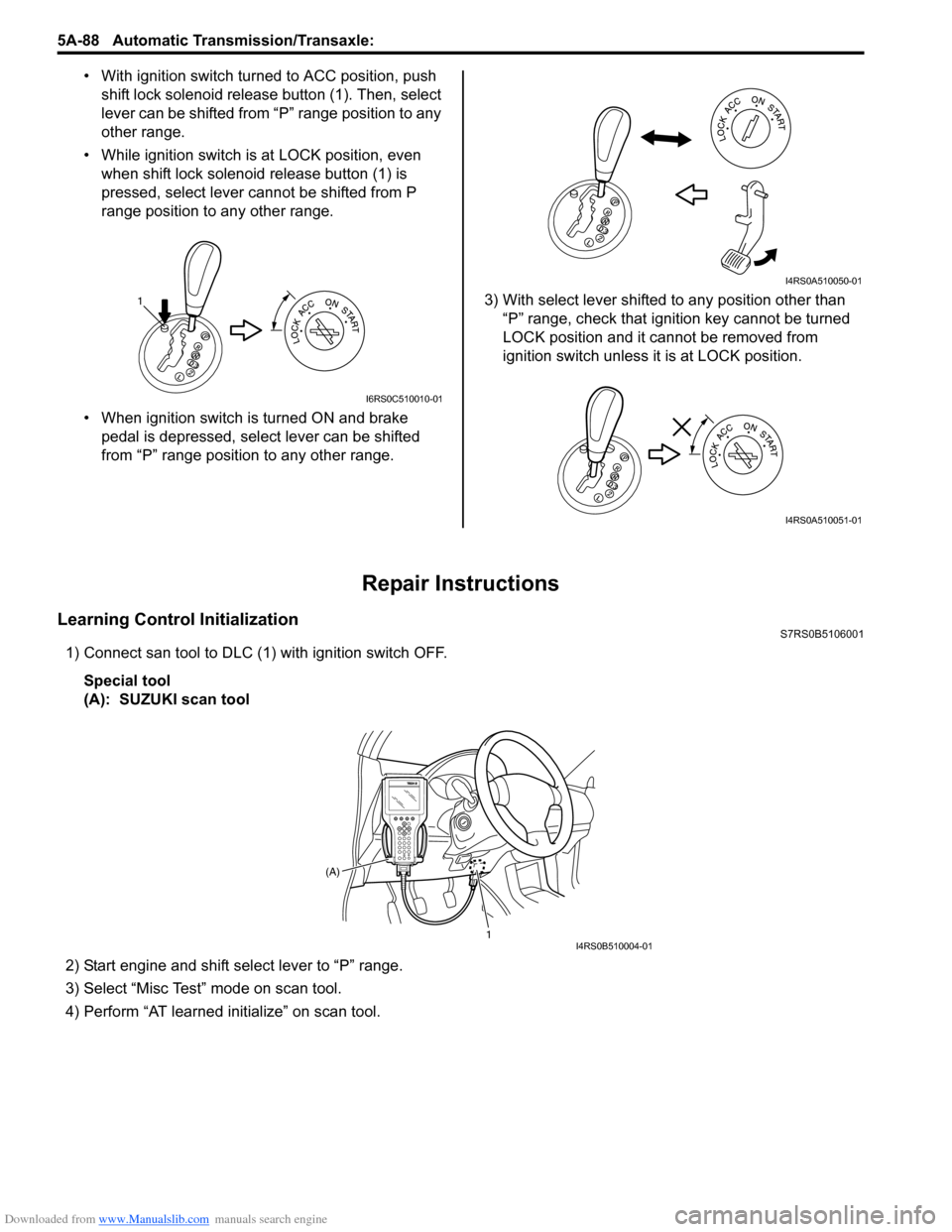
• With ignition switch turned to ACC position, push
shift lock solenoid release button (1). Then, select
lever can be shifted from “P” range position to any
other range.
• While ignition switch is at LOCK position, even when shift lock solenoid release button (1) is
pressed, select lever cannot be shifted from P
range position to any other range.
• When ignition switch is turned ON and brake pedal is depressed, select lever can be shifted
from “P” range position to any other range. 3) With select lever shifted to any position other than
“P” range, check that ignition key cannot be turned
LOCK position and it cannot be removed from
ignition switch unless it is at LOCK position.
Repair Instructions
Learning Control InitializationS7RS0B5106001
1) Connect san tool to DLC (1) with ignition switch OFF.
Special tool
(A): SUZUKI scan tool
2) Start engine and shift select lever to “P” range.
3) Select “Misc Test” mode on scan tool.
4) Perform “AT learned initialize” on scan tool.
1
I6RS0C510010-01
I4RS0A510050-01
I4RS0A510051-01
1
(A)I4RS0B510004-01
Page 735 of 1496

Downloaded from www.Manualslib.com manuals search engine Automatic Transmission/Transaxle: 5A-91
Select Lever InspectionS7RS0B5106007
Check select lever for smooth and clear-cut movement
individually. If a malfunction is found, replace select lever
assembly.
“3” Position Switch InspectionS7RS0B5106008
1) Remove console box referring to “Console Box Components in Section 9H”.
2) Disconnect “3” position switch connector (1).
3) Check continuity between “3” position switch terminals.
“3” position switch specification
Shift select lever to “3 ” or “2” range: Continuity
Shift other above range: No continuity
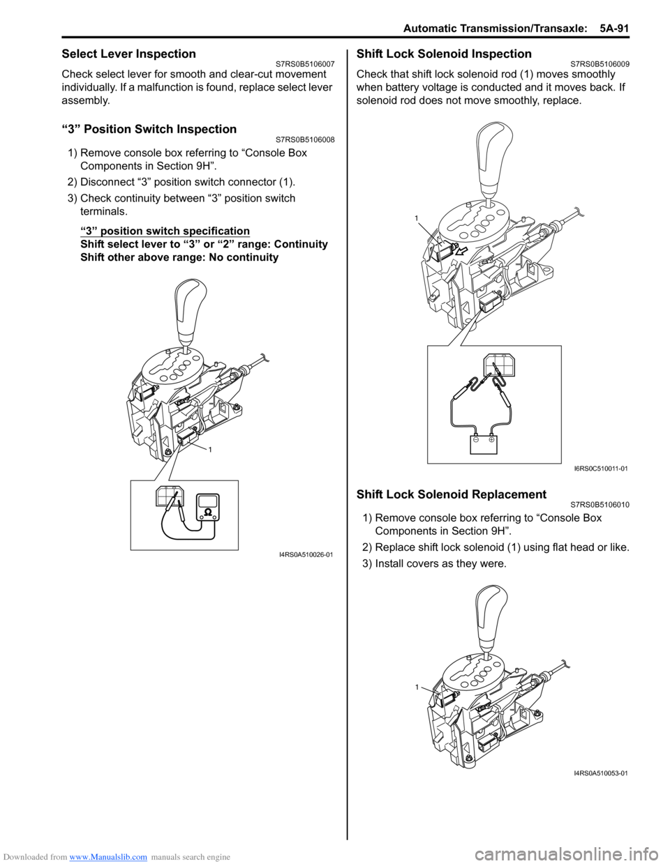
Shift Lock Solenoid InspectionS7RS0B5106009
Check that shift lock soleno id rod (1) moves smoothly
when battery voltage is conducted and it moves back. If
solenoid rod does not move smoothly, replace.
Shift Lock Solenoid ReplacementS7RS0B5106010
1) Remove console box referring to “Console Box Components in Section 9H”.
2) Replace shift lock solenoid (1) using flat head or like.
3) Install covers as they were.
1
I4RS0A510026-01
1
I6RS0C510011-01
1
I4RS0A510053-01
Page 738 of 1496

Downloaded from www.Manualslib.com manuals search engine 5A-94 Automatic Transmission/Transaxle:
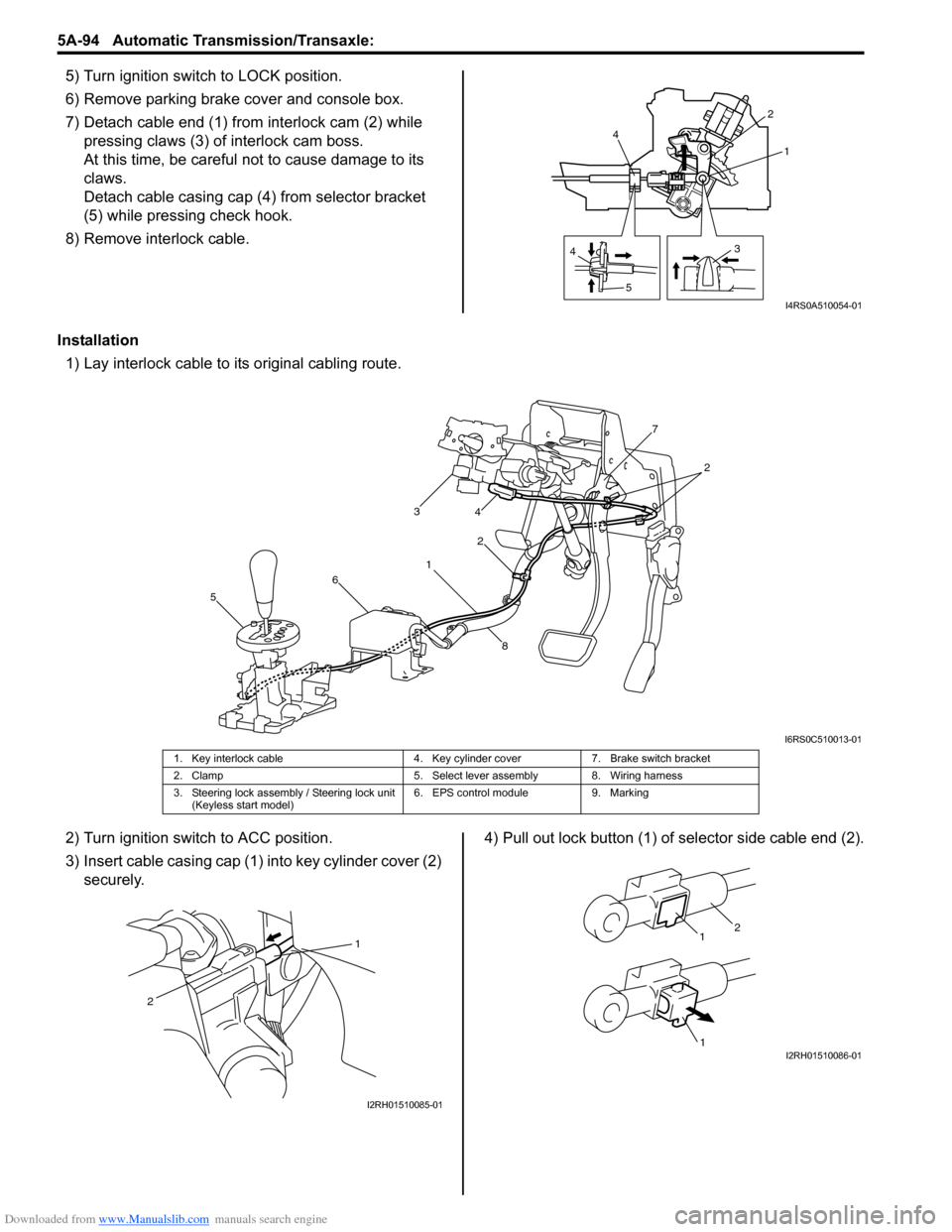
5) Turn ignition switch to LOCK position.
6) Remove parking brake cover and console box.
7) Detach cable end (1) from interlock cam (2) while
pressing claws (3) of interlock cam boss.
At this time, be careful no t to cause damage to its
claws.
Detach cable casing cap (4 ) from selector bracket
(5) while pressing check hook.
8) Remove interlock cable.
Installation 1) Lay interlock cable to its original cabling route.
2) Turn ignition switch to ACC position.
3) Insert cable casing cap (1) into key cylinder cover (2) securely. 4) Pull out lock button (1) of selector side cable end (2).
4
5 31
2
4
I4RS0A510054-01
1 2
3
4
5 6 7
8
2
I6RS0C510013-01
1. Key interlock cable 4. Key cylinder cover7. Brake switch bracket
2. Clamp 5. Select lever assembly 8. Wiring harness
3. Steering lock assembly / Steering lock unit (Keyless start model) 6. EPS control module
9. Marking
1
2
I2RH01510085-01
1
1
2
I2RH01510086-01
Page 747 of 1496

Downloaded from www.Manualslib.com manuals search engine Automatic Transmission/Transaxle: 5A-103
Installation
Reverse removal procedure noting the following.
• Connect TCM connectors securely.
• If the vehicle is equipped with air bag system, be sure to enable air bag system after TCM is back in place.
Refer to “Enabling Air Bag System in Section 8B”.
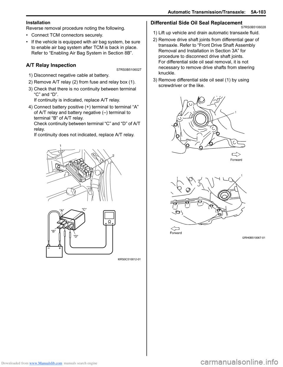
A/T Relay InspectionS7RS0B5106027
1) Disconnect negative cable at battery.
2) Remove A/T relay (2) from fuse and relay box (1).
3) Check that there is no continuity between terminal “C” and “D”.
If continuity is indicated, replace A/T relay.
4) Connect battery positive (+ ) terminal to terminal “A”
of A/T relay and battery negative (–) terminal to
terminal “B” of A/T relay.
Check continuity between terminal “C” and “D” of A/T
relay.
If continuity does not indicated, replace A/T relay.
Differential Side Oil Seal ReplacementS7RS0B5106028
1) Lift up vehicle and drain automatic transaxle fluid.
2) Remove drive shaft joints from differential gear of transaxle. Refer to “Front Drive Shaft Assembly
Removal and Installation in Section 3A” for
procedure to disconnect drive shaft joints.
For differential side oil seal removal, it is not
necessary to remove drive shafts from steering
knuckle.
3) Remove differential side oil seal (1) by using screwdriver or the like.
"D"
"B" "A"
"C"
1
2
I6RS0C510012-01
I2RH0B510067-01
Page 752 of 1496
Downloaded from www.Manualslib.com manuals search engine 5A-108 Automatic Transmission/Transaxle:
Automatic Transaxle Assembly ComponentsS7RS0B5106032
I6RS0C510016-04
Page 767 of 1496

Downloaded from www.Manualslib.com manuals search engine Automatic Transmission/Transaxle: 5A-123
2) Check tip clearance of both drive and driven gears.Using a feeler gauge, m easure clearance between
drive and driven gear tips. If clearance exceeds its
standard value, replace oil pump assembly.
Tip clearance between oil pump drive gear and
oil pump driven gear
Standard: 0.07 – 0.15 mm (0.0028 – 0.0059 in.)
3) Check side clearance of both gears. Using a straightedge (1) and a feeler gauge (2),
measure side clearance between gears and pump
body.
If clearance exceeds its standard value, replace oil
pump assembly.
Side clearance between gears and oil pump body
Standard: 0.02 – 0.05 mm (0.0008 – 0.0019 in.)
4) Using special tool, measure stator shaft bush (1) bore.
If measured stator shaft bush bore is out of
specifications, replace oil pump assembly with new
one.
Special tool
(A): 09900–20605
Stator shaft bush bore
Standard: 18.424 – 18.450 mm (0.7254 – 0.7264
in.) 5) Install direct clutch asse
mbly (1) to stator shaft
assembly (2), then ensure that direct clutch
assembly turns smoothly.
If unsmooth rotation or noise are found in oil pump
assembly, replace oil pump assembly with new one.
This check should also be done to input shaft
assembly and replace input shaft assembly if
necessary.
6) Using special tool, measure oil pump body bush bore.
If measured oil pump body bush (1) bore is out of
specifications, replace o il pump assembly with new
one. Torque converter also needs to be checked.
Replace torque converter, if necessary.
Special tool
(A): 09900–20605
Oil pump body bush bore
Standard: 38.113 – 38.138 mm (1.5005 – 1.5015
in.)
I2RH0B510155-01
I2RH0B510156-01
I2RH0B510157-01
I2RH0B510158-01
I2RH0B510159-01