2008 SUZUKI SWIFT air condition
[x] Cancel search: air conditionPage 1022 of 1496
Downloaded from www.Manualslib.com manuals search engine 7B-74 Air Conditioning System: Automatic Type
Air Flow Control Actuator Removal and
Installation
S7RS0B7226006
Removal1) Disconnect negative (–) cable at battery.
2) Remove steering column hol e cover from instrument
panel.
3) Remove foot duct from HVAC unit.
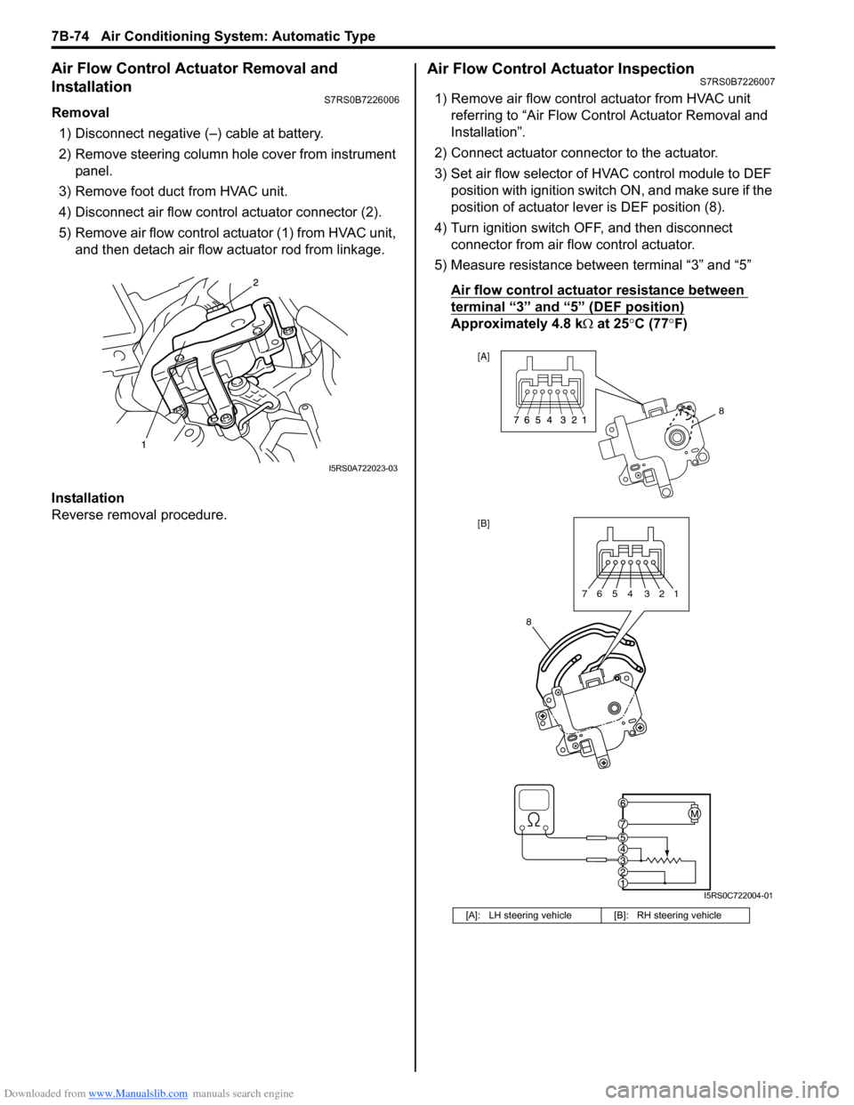
4) Disconnect air flow contro l actuator connector (2).
5) Remove air flow control actuator (1) from HVAC unit, and then detach air flow actuator rod from linkage.
Installation
Reverse removal procedure.
Air Flow Control Actuator InspectionS7RS0B7226007
1) Remove air flow control actuator from HVAC unit referring to “Air Flow C ontrol Actuator Removal and
Installation”.
2) Connect actuator connector to the actuator.
3) Set air flow selector of HVAC control module to DEF position with ignition switch ON, and make sure if the
position of actuator lever is DEF position (8).
4) Turn ignition switch OFF, and then disconnect connector from air flow control actuator.
5) Measure resistance between terminal “3” and “5”
Air flow control actuator resistance between
terminal “3” and “5” (DEF position)
Approximately 4.8 k Ω at 25 °C (77 °F)
I5RS0A722023-03
[A]: LH steering vehicle [B]: RH steering vehicle
8
[A]
[B]
8
7654 321
I5RS0C722004-01
Page 1023 of 1496
Downloaded from www.Manualslib.com manuals search engine Air Conditioning System: Automatic Type 7B-75
6) Connect connector to air flow control actuator.
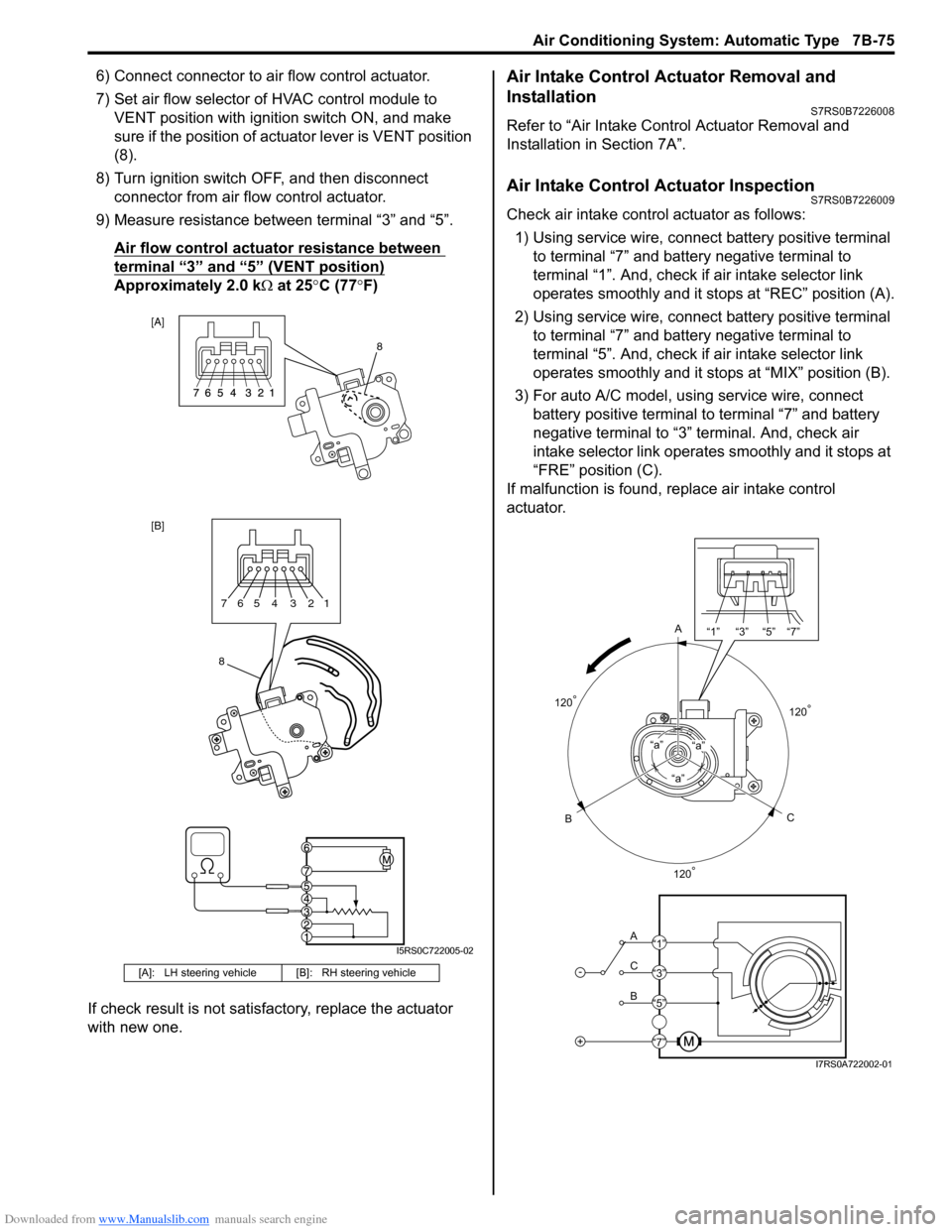
7) Set air flow selector of HVAC control module to VENT position with ignition switch ON, and make
sure if the position of act uator lever is VENT position
(8).
8) Turn ignition switch OFF, and then disconnect connector from air flow control actuator.
9) Measure resistance between terminal “3” and “5”.
Air flow control actuator resistance between
terminal “3” and “5” (VENT position)
Approximately 2.0 k Ω at 25 °C (77 °F)
If check result is not satisfactory, replace the actuator
with new one.
Air Intake Control Actuator Removal and
Installation
S7RS0B7226008
Refer to “Air Intake Control Actuator Removal and
Installation in Section 7A”.
Air Intake Control Actuator InspectionS7RS0B7226009
Check air intake contro l actuator as follows:
1) Using service wire, connect battery positive terminal
to terminal “7” and battery negative terminal to
terminal “1”. And, check if air intake selector link
operates smoothly and it stops at “REC” position (A).
2) Using service wire, connect battery positive terminal
to terminal “7” and battery negative terminal to
terminal “5”. And, check if air intake selector link
operates smoothly and it stops at “MIX” position (B).
3) For auto A/C model, using service wire, connect battery positive terminal to terminal “7” and battery
negative terminal to “3” terminal. And, check air
intake selector link operates smoothly and it stops at
“FRE” position (C).
If malfunction is found, replace air intake control
actuator.
[A]: LH steering vehicl e [B]: RH steering vehicle
[A]
[B]
8
8765 4 3 21
I5RS0C722005-02
A
C
B“a”
“a”“a”
-
+
A
C
B “1” “3” “5” “7”
“1”
“3”
“5”
“7”
120
°
120° 120
°
I7RS0A722002-01
Page 1024 of 1496
Downloaded from www.Manualslib.com manuals search engine 7B-76 Air Conditioning System: Automatic Type
Actuator Linkage InspectionS7RS0B7226010
• Check if each actuator linkage operates smoothly.
• Check actuator rod for bend.
• Check each actuator linkage for breakage.
• Make sure if there is not any obstruction in operating range of actuator linkage.
If any malfunction is found, repair or replace faulty
part(s).
Blower Motor Controller Removal and
Installation
S7RS0B7226011
Refer to “Blower Motor Resistor Removal and
Installation in Section 7A”.
Blower Motor Controller InspectionS7RS0B7226012
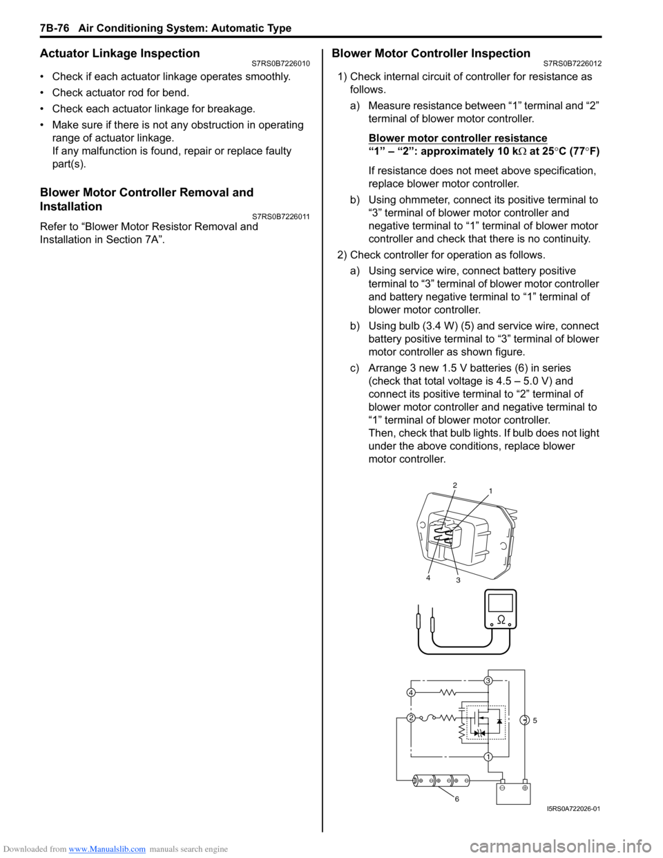
1) Check internal circuit of controller for resistance as follows.
a) Measure resistance between “1” terminal and “2” terminal of blower motor controller.
Blower motor cont roller resistance
“1” – “2”: approximately 10 k Ω at 25 °C (77 °F)
If resistance does not meet above specification,
replace blower motor controller.
b) Using ohmmeter, connect its positive terminal to “3” terminal of blower motor controller and
negative terminal to “1” terminal of blower motor
controller and check that there is no continuity.
2) Check controller for operation as follows. a) Using service wire, connect battery positive terminal to “3” terminal of blower motor controller
and battery negative terminal to “1” terminal of
blower motor controller.
b) Using bulb (3.4 W) (5) and service wire, connect battery positive terminal to “3” terminal of blower
motor controller as shown figure.
c) Arrange 3 new 1.5 V batteries (6) in series (check that total voltage is 4.5 – 5.0 V) and
connect its positive term inal to “2” terminal of
blower motor controller and negative terminal to
“1” terminal of blower motor controller.
Then, check that bulb lights. If bulb does not light
under the above conditions, replace blower
motor controller.
3
1
2
4
2
1
3
4
5
6I5RS0A722026-01
Page 1025 of 1496
Downloaded from www.Manualslib.com manuals search engine Air Conditioning System: Automatic Type 7B-77
HVAC Control Module Removal and InstallationS7RS0B7226013
Removal1) Disconnect negative (–) cable at battery.
2) Disable air bag system referring to “Disabling Air Bag System in Section 8B”.
3) Remove passenger air bag module from instrument panel referring to “Passenger Air Bag (Inflator)
Module Removal and Installation in Section 8B”.
4) Remove radio assembly from instrument panel referring to “Rear Speaker Removal and Installation
in Section 9C”.
5) Remove two connectors fr om HVAC control module.
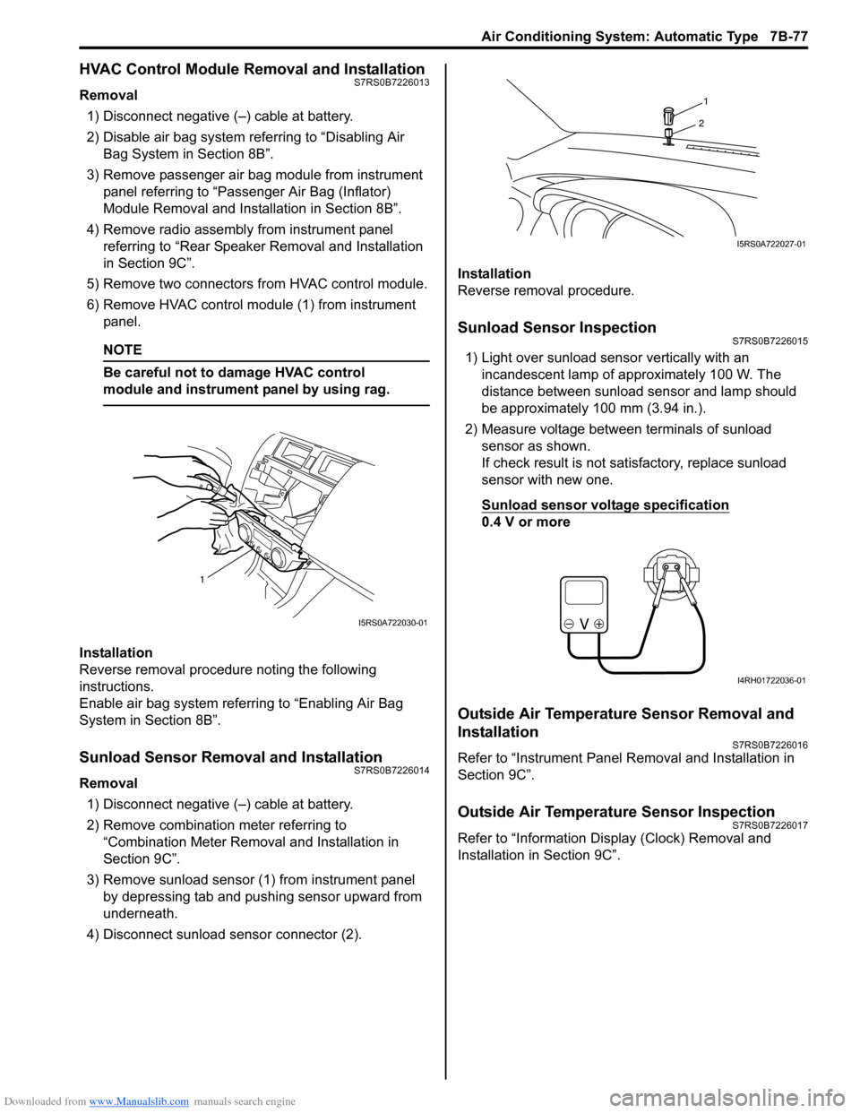
6) Remove HVAC control modu le (1) from instrument
panel.
NOTE
Be careful not to damage HVAC control
module and instrument panel by using rag.
Installation
Reverse removal procedure noting the following
instructions.
Enable air bag system referring to “Enabling Air Bag
System in Section 8B”.
Sunload Sensor Removal and InstallationS7RS0B7226014
Removal
1) Disconnect negative (–) cable at battery.
2) Remove combination meter referring to “Combination Meter Removal and Installation in
Section 9C”.
3) Remove sunload sensor (1) from instrument panel by depressing tab and pushing sensor upward from
underneath.
4) Disconnect sunload sensor connector (2). Installation
Reverse removal procedure.
Sunload Sensor InspectionS7RS0B7226015
1) Light over sunload sensor vertically with an
incandescent lamp of approximately 100 W. The
distance between sunload sensor and lamp should
be approximately 100 mm (3.94 in.).
2) Measure voltage between terminals of sunload sensor as shown.
If check result is not satisfactory, replace sunload
sensor with new one.
Sunload sensor voltage specification
0.4 V or more
Outside Air Temperature Sensor Removal and
Installation
S7RS0B7226016
Refer to “Instrument Panel Re moval and Installation in
Section 9C”.
Outside Air Temperature Sensor InspectionS7RS0B7226017
Refer to “Information Display (Clock) Removal and
Installation in Section 9C”.
1
I5RS0A722030-01
1
2
I5RS0A722027-01
I4RH01722036-01
Page 1026 of 1496
Downloaded from www.Manualslib.com manuals search engine 7B-78 Air Conditioning System: Automatic Type
Inside Air Temperature Sensor Removal and
Installation
S7RS0B7226018
Removal1) Disconnect negative (–) cable at battery.
2) Remove steering column hole cover.
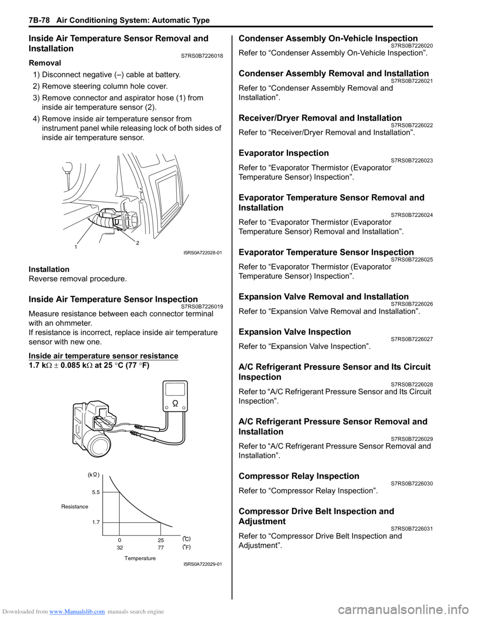
3) Remove connector and aspirator hose (1) from inside air temperature sensor (2).
4) Remove inside air temperature sensor from instrument panel while releas ing lock of both sides of
inside air temperature sensor.
Installation
Reverse removal procedure.
Inside Air Temperature Sensor InspectionS7RS0B7226019
Measure resistance between each connector terminal
with an ohmmeter.
If resistance is incorrect, replace inside air temperature
sensor with new one.
Inside air temperature sensor resistance
1.7 k Ω ± 0.085 k Ω at 25 °C (77 ° F)
Condenser Assembly On-Vehicle InspectionS7RS0B7226020
Refer to “Condenser Assembly On-Vehicle Inspection”.
Condenser Assembly Removal and InstallationS7RS0B7226021
Refer to “Condenser Assembly Removal and
Installation”.
Receiver/Dryer Removal and InstallationS7RS0B7226022
Refer to “Receiver/Dryer Removal and Installation”.
Evaporator InspectionS7RS0B7226023
Refer to “Evaporator Thermistor (Evaporator
Temperature Sensor) Inspection”.
Evaporator Temperature Sensor Removal and
Installation
S7RS0B7226024
Refer to “Evaporator Thermistor (Evaporator
Temperature Sensor) Removal and Installation”.
Evaporator Temperature Sensor InspectionS7RS0B7226025
Refer to “Evaporator Thermistor (Evaporator
Temperature Sensor) Inspection”.
Expansion Valve Removal and InstallationS7RS0B7226026
Refer to “Expansion Valve Removal and Installation”.
Expansion Valve InspectionS7RS0B7226027
Refer to “Expansion Valve Inspection”.
A/C Refrigerant Pressure Sensor and Its Circuit
Inspection
S7RS0B7226028
Refer to “A/C Refrigerant Pressure Sensor and Its Circuit
Inspection”.
A/C Refrigerant Pressure Sensor Removal and
Installation
S7RS0B7226029
Refer to “A/C Refrigerant Pressure Sensor Removal and
Installation”.
Compressor Relay InspectionS7RS0B7226030
Refer to “Compressor Relay Inspection”.
Compressor Drive Belt Inspection and
Adjustment
S7RS0B7226031
Refer to “Compressor Drive Belt Inspection and
Adjustment”.
12I5RS0A722028-01
Temperature
Resistance
1.7
0
32 25
77
F
5.5
I5RS0A722029-01
Page 1027 of 1496
Downloaded from www.Manualslib.com manuals search engine Air Conditioning System: Automatic Type 7B-79
Compressor Drive Belt Removal and
Installation
S7RS0B7226032
Refer to “Compressor Drive Belt Removal and
Installation”.
Compressor Assembly Removal and
Installation
S7RS0B7226033
Refer to “Compressor Assembly Removal and
Installation”.
Compressor Assembly ComponentsS7RS0B7226034
Refer to “Compressor Assembly Components”.
Magnet Clutch Removal and InstallationS7RS0B7226035
Refer to “Magnet Clutch Removal and Installation”.
Magnet Clutch InspectionS7RS0B7226036
Refer to “Magnet Clutch Inspection”.
Relief Valve InspectionS7RS0B7226039
Refer to “Relief Valve Inspection”.
Special Tools and Equipment
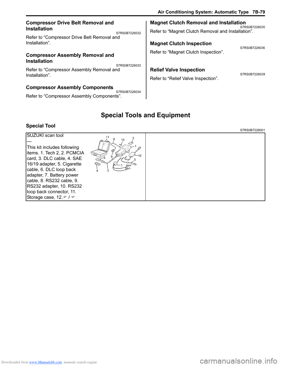
Special ToolS7RS0B7228001
SUZUKI scan tool
—
This kit includes following
items. 1. Tech 2, 2. PCMCIA
card, 3. DLC cable, 4. SAE
16/19 adapter, 5. Cigarette
cable, 6. DLC loop back
adapter, 7. Battery power
cable, 8. RS232 cable, 9.
RS232 adapter, 10. RS232
loop back connector, 11.
Storage case, 12.�) / �)
Page 1028 of 1496
Downloaded from www.Manualslib.com manuals search engine 7B-80 Air Conditioning System: Automatic Type
Page 1032 of 1496
Downloaded from www.Manualslib.com manuals search engine 8A-1 Seat Belts:
Restraint
Seat Belts
Precautions
Precautions on Service and Diagnosis of Seat
Belt
S7RS0B8100001
WARNING!
If replacing seat belt is necessary, replace
buckle and seat belt assembly together as a
set. This is for the reason of ensuring locking
of tongue plate with buckle. If these parts are
replaced individually, such a locking
condition may become unreliable. For this
reason, SUZUKI will supply only the spare
buckle and seat belt assembly in a set part.
Before servicing or replacing seat belts, refer to the
following precautionary items.
• Seat belts should be normal relative to strap retractor and buckle portions. • Keep sharp edges and damaging objects away from
belts.
• Avoid bending or damaging any portion of belt buckle or latch plate.
• Do not bleach or dye belt webbing. (Use only mild soap and lukewarm water to clean it.)
• When installing a seat belt anchor bolt, it should be tightened by hand at first to prevent cross-threading
and then to specified torque.
• Do not attempt any repair s on retractor mechanisms
or retractor covers. Replace defective assemblies with
new replacement parts.
• Keep belts dry and clean at all times.
• If there exist any parts in question, replace such parts.
• Replace belts whose webbing is cut or otherwise damaged.
• Do not put anything into trim panel opening which seat belt webbing passes through.
General Description
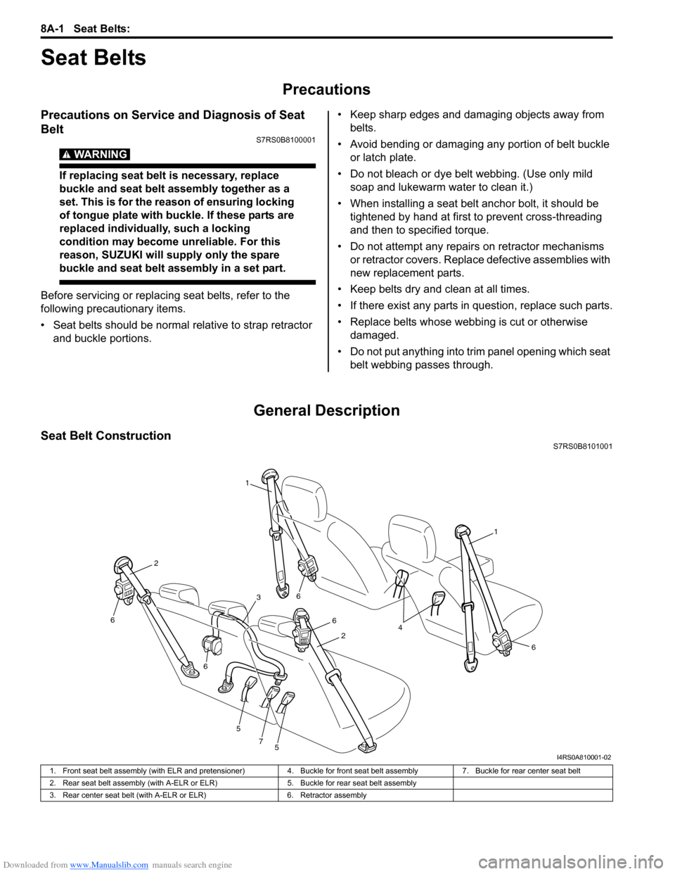
Seat Belt ConstructionS7RS0B8101001
1
1
6
6
6
5
5
7
6
6
2
2
3
4
I4RS0A810001-02
1. Front seat belt assembly (with ELR and pretensioner) 4. Buckle for front seat belt assembly7. Buckle for rear center seat belt
2. Rear seat belt assembly (with A-ELR or ELR) 5. Buckle for rear seat belt assembly
3. Rear center seat belt (with A-ELR or ELR) 6. Retractor assembly