Page 1349 of 1496
Downloaded from www.Manualslib.com manuals search engine Security and Locks: 9F-3
Diagnostic Information and Procedures
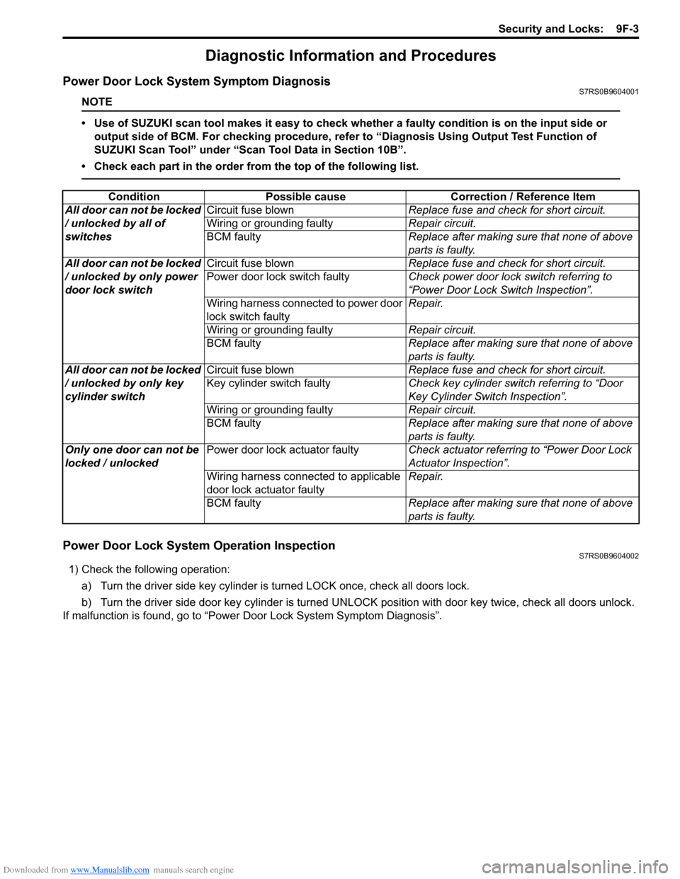
Power Door Lock System Symptom DiagnosisS7RS0B9604001
NOTE
• Use of SUZUKI scan tool makes it easy to check whether a faulty condition is on the input side or
output side of BCM. For checking procedure, re fer to “Diagnosis Using Output Test Function of
SUZUKI Scan Tool” under “Scan Tool Data in Section 10B”.
• Check each part in the order from the top of the following list.
Power Door Lock System Operation InspectionS7RS0B9604002
1) Check the following operation:
a) Turn the driver side key cylinder is turned LOCK once, check all doors lock.
b) Turn the driver side door key cylinder is turned UNLOC K position with door key twice, check all doors unlock.
If malfunction is found, go to “Power Door Lock System Symptom Diagnosis”.
Condition Possible cause Correction / Reference Item
All door can not be locked
/ unlocked by all of
switches Circuit fuse blown
Replace fuse and check for short circuit.
Wiring or grounding faulty Repair circuit.
BCM faulty Replace after making sure that none of above
parts is faulty.
All door can not be locked
/ unlocked by only power
door lock switch Circuit fuse blown
Replace fuse and check for short circuit.
Power door lock switch faulty Check power door lock switch referring to
“Power Door Lock Switch Inspection”.
Wiring harness connected to power door
lock switch faulty Repair.
Wiring or grounding faulty Repair circuit.
BCM faulty Replace after making sure that none of above
parts is faulty.
All door can not be locked
/ unlocked by only key
cylinder switch Circuit fuse blown
Replace fuse and check for short circuit.
Key cylinder switch faulty Check key cylinder switch referring to “Door
Key Cylinder Switch Inspection”.
Wiring or grounding faulty Repair circuit.
BCM faulty Replace after making sure that none of above
parts is faulty.
Only one door can not be
locked / unlocked Power door lock actuator faulty
Check actuator referring to “Power Door Lock
Actuator Inspection”.
Wiring harness connected to applicable
door lock actuator faulty Repair.
BCM faulty Replace after making sure that none of above
parts is faulty.
Page 1361 of 1496
Downloaded from www.Manualslib.com manuals search engine Security and Locks: 9F-15
Keyless Entry Receiver and Its Circuit InspectionS7RS0B9606018
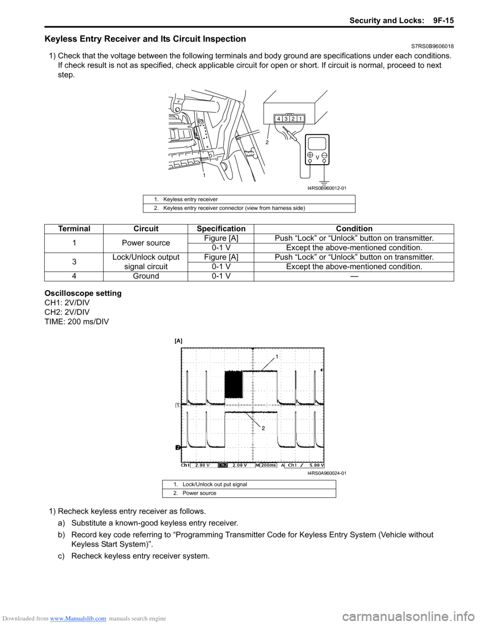
1) Check that the voltage between the following terminals and body ground are specifications under each conditions.
If check result is not as specified, ch eck applicable circuit for open or short. If circuit is normal, proceed to next
step.
Oscilloscope setting
CH1: 2V/DIV
CH2: 2V/DIV
TIME: 200 ms/DIV 1) Recheck keyless entry receiver as follows.
a) Substitute a known-good keyless entry receiver.
b) Record key code referring to “Programming Transmit ter Code for Keyless Entry System (Vehicle without
Keyless Start System)”.
c) Recheck keyless entry receiver system.
1. Keyless entry receiver
2. Keyless entry receiver connector (view from harness side)
1234
V
1 2
I4RS0B960012-01
Terminal
Circuit Specification Condition
1 Power source Figure [A] Push “Lock” or “Unlock” button on transmitter.
0-1 V Except the above-mentioned condition.
3 Lock/Unlock output
signal circuit Figure [A] Push “Lock” or “Unlock” button on transmitter.
0-1 V Except the above-mentioned condition.
4G ro un d0 -1 V —
1. Lock/Unlock out put signal
2. Power source
I4RS0A960024-01
Page 1363 of 1496
Downloaded from www.Manualslib.com manuals search engine Seats: 9G-1
Body, Cab and Accessories
Seats
Repair Instructions
Front Seat ComponentsS7RS0B9706001
2
4
1 3
11
6
3
4
6
7
8
(b)
(b)
10
5
(a)
or
94
5
(c)
(b)
10
or
A
A
B
AB
B
A
I6RS0C970001-02
1. Seat cushion 6. Knob or 11. Riser bolt
: Apply thread lock 99000-32100 or 99000-32030
to all around thread part of bolt.
2. Seat back 7. Side air bag module (if equipped) : 23 N⋅m (2.3 kgf-m, 17.0 lb-ft)
3. Riser nut 8. Side air bag harness (if equipped) : 35 N⋅m (3.5 kgf-m, 25.5 lb-ft)
4. Cover or 9. Seat mounting bolt
: Apply thread lock 99000-32100 or 99000-
32030 to all around thread part of bolt. :28 N
⋅m (2.8 kgf-m, 20.5 lb-ft) (Seat lifter type)
35 N ⋅m (3.5 kgf-m, 25.5 lb-ft) (Non seat lifter
type)
5. Seat adjuster 10. Seat back mounting bolt
Page 1364 of 1496
Downloaded from www.Manualslib.com manuals search engine 9G-2 Seats:
Front Seat Removal and InstallationS7RS0B9706002
WARNING!
Refer to “Air Bag Warning in Section 00” before starting service work.
Removal1) Disable air bag system referring to “Disabling Air Bag System in Section 8B”.
2) Disconnect couplers for seat harness and side air bag, if equipped.
3) Remove 4 mounting bolts to remove seat assembly.
4) Disassemble and repair seat if necessary.
Installation
Reverse removal procedure to install front seat.
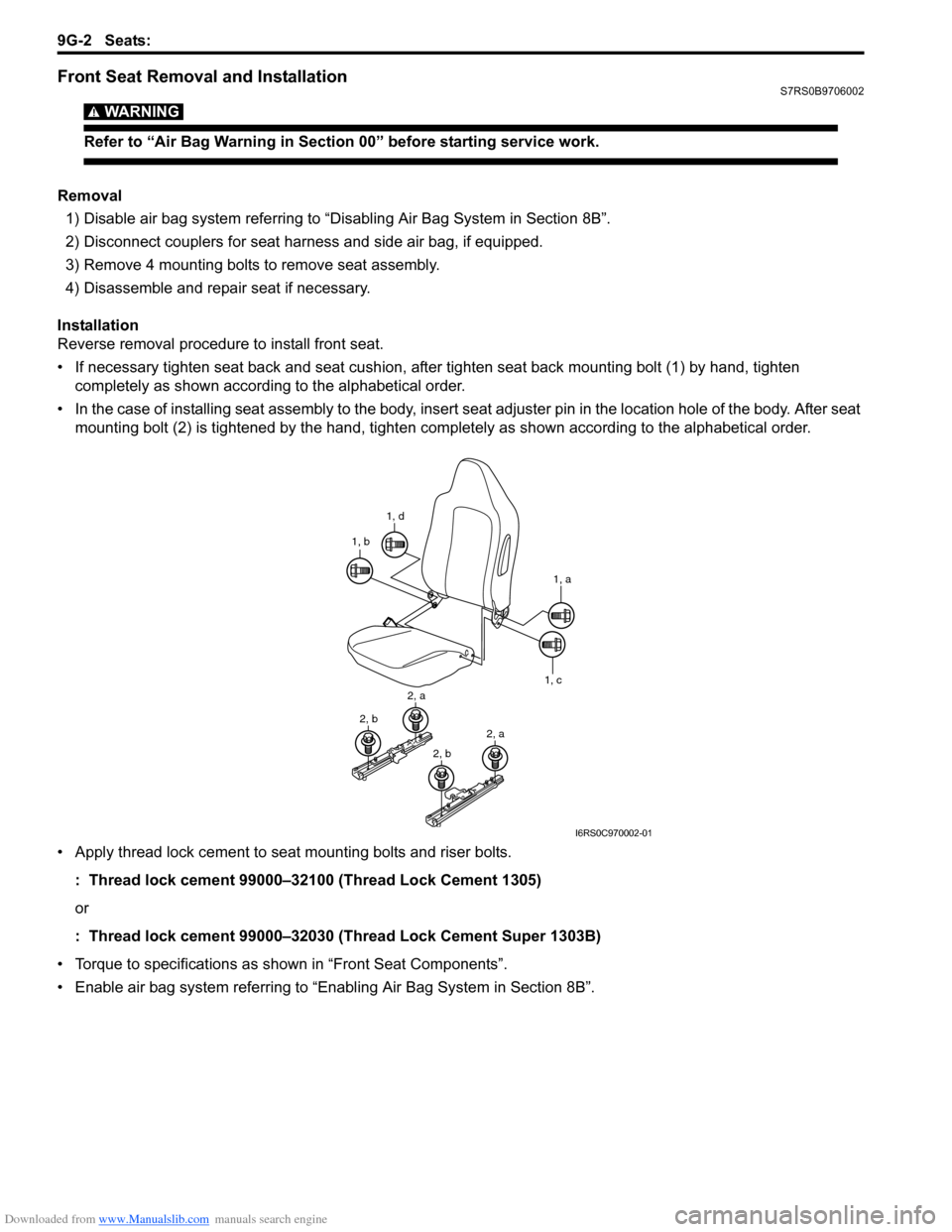
• If necessary tighten seat back and seat cushion, after tighten seat back mounting bolt (1) by hand, tighten completely as shown according to the alphabetical order.
• In the case of installing seat assembly to the body, insert se at adjuster pin in the location hole of the body. After seat
mounting bolt (2) is tightened by t he hand, tighten completely as shown according to the alphabetical order.
• Apply thread lock cement to seat mounting bolts and riser bolts. : Thread lock cement 99000–32100 (Thread Lock Cement 1305)
or
: Thread lock cement 99000–32030 (Thread Lock Cement Super 1303B)
• Torque to specifications as shown in “Front Seat Components”.
• Enable air bag system referring to “Enabling Air Bag System in Section 8B”.
1, d
1, b
1, a
1, c
2, a
2, b2, a
2, b
I6RS0C970002-01
Page 1372 of 1496
Downloaded from www.Manualslib.com manuals search engine 9J-3 Hood / Fenders / Doors:
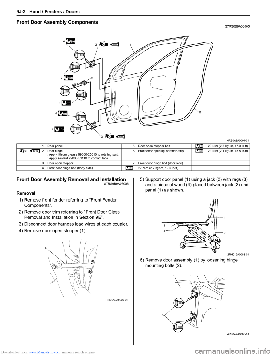
Front Door Assembly ComponentsS7RS0B9A06005
Front Door Assembly Removal and InstallationS7RS0B9A06006
Removal1) Remove front fender referring to “Front Fender Components”.
2) Remove door trim referring to “Front Door Glass Removal and Installa tion in Section 9E”.
3) Disconnect door harness lead wires at each coupler.
4) Remove door open stopper (1). 5) Support door panel (1) using a jack (2) with rags (3)
and a piece of wood (4) placed between jack (2) and
panel (1) as shown.
6) Remove door assembly (1) by loosening hinge mounting bolts (2).
2
21(a)4
(a)4
3(b)7
(b)7
(c)5
6
I4RS0A9A0004-01
1. Door panel 5. Door open stopper bolt: 23 N⋅m (2.3 kgf-m, 17.0 lb-ft)
2. Door hinge : Apply lithium grease 99000-25010 to rotating part.
: Apply sealant 99000-31110 to contact face. 6. Front door opening weather-strip
: 21 N⋅m (2.1 kgf-m, 15.5 lb-ft)
3. Door open stopper 7. Front door hinge bolt (door side)
4. Front door hinge bolt (body side) : 27 N⋅m (2.7 kgf-m, 19.5 lb-ft)
I4RS0A9A0005-01
I2RH019A0003-01
1
2
I4RS0A9A0006-01
Page 1375 of 1496
Downloaded from www.Manualslib.com manuals search engine Hood / Fenders / Doors: 9J-6
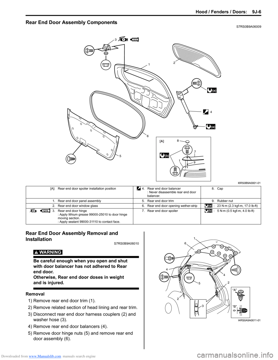
Rear End Door Assembly ComponentsS7RS0B9A06009
Rear End Door Assembly Removal and
Installation
S7RS0B9A06010
WARNING!
Be careful enough when you open and shut
with door balancer has not adhered to Rear
end door.
Otherwise, Rear end door doses in weight
and is injured.
Removal1) Remove rear end door trim (1).
2) Remove related section of head lining and rear trim.
3) Disconnect rear end door harness couplers (2) and washer hose (3).
4) Remove rear end door balancers (4).
5) Remove door hinge nuts (5) and remove rear end door assembly (6).
3
(a)
(a)
12
6
5
[A]
1
7
9
8
(b)
4
I6RS0B9A0001-01
[A]: Rear end door spoiler installation position 4. Rear end door balancer
: Never disassemble rear end door
balancer. 8. Cap
1. Rear end door panel assembly 5. Rear end door trim9. Rubber nut
2. Rear end door window glass 6. Rear end door opening wether-strip: 23 N⋅m (2.3 kgf-m, 17.0 lb-ft)
3. Rear end door hinge : Apply lithium grease 99000-25010 to door hinge
moving section.
: Apply sealant 99000-31110 to contact face. 7. Rear end door spoiler
: 5 N⋅m (0.5 kgf-m, 4.0 lb-ft)
“A”
“B”
“B”
“A”“B”“A”“A”“A”
“A”“A”“A”
“A”
1
6
5 4
2
3
2
4
I4RS0A9A0011-01
Page 1376 of 1496
Downloaded from www.Manualslib.com manuals search engine 9J-7 Hood / Fenders / Doors:
WARNING!
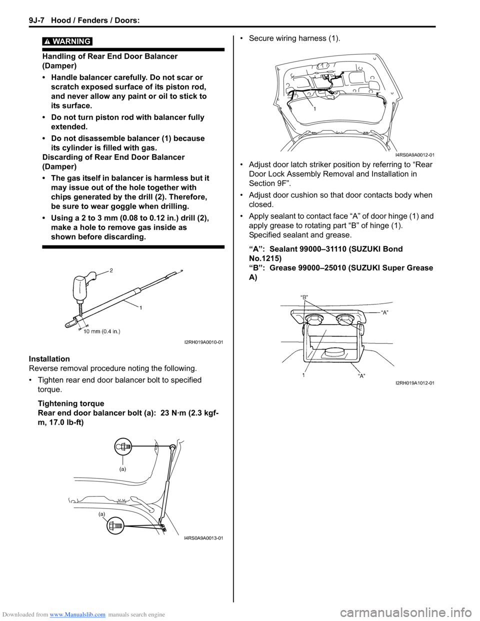
Handling of Rear End Door Balancer
(Damper)
• Handle balancer carefully. Do not scar or scratch exposed surface of its piston rod,
and never allow any paint or oil to stick to
its surface.
• Do not turn piston rod with balancer fully extended.
• Do not disassemble balancer (1) because its cylinder is filled with gas.
Discarding of Rear End Door Balancer
(Damper)
• The gas itself in balancer is harmless but it may issue out of the hole together with
chips generated by th e drill (2). Therefore,
be sure to wear goggle when drilling.
• Using a 2 to 3 mm (0.08 to 0.12 in.) drill (2),
make a hole to remove gas inside as
shown before discarding.
Installation
Reverse removal procedure noting the following.
• Tighten rear end door balancer bolt to specified torque.
Tightening torque
Rear end door balancer bolt (a): 23 N·m (2.3 kgf-
m, 17.0 lb-ft) • Secure wiring harness (1).
• Adjust door latch striker position by referring to “Rear
Door Lock Assembly Removal and Installation in
Section 9F”.
• Adjust door cushion so that door contacts body when closed.
• Apply sealant to contact face “A” of door hinge (1) and apply grease to rotating part “B” of hinge (1).
Specified sealant and grease.
“A”: Sealant 99000–31110 (SUZUKI Bond
No.1215)
“B”: Grease 99000–25010 (SUZUKI Super Grease
A)
I2RH019A0010-01
(a)
(a)
I4RS0A9A0013-01
1
I4RS0A9A0012-01
I2RH019A1012-01
Page 1410 of 1496
Downloaded from www.Manualslib.com manuals search engine 10B-7 Body Electrical Control System:
Connector Layout Diagram of BCM and Junction Block AssemblyS7RS0BA202002
BCM and junction block assembly connectors (viewed from harness side)
I4RS0AA20004-01
[A]: Junction block assembly (viewed from BCM side)2. Junction block assembly5. Rear wiper relay
[B]: Junction block assembly (viewed from relay side) 3.Heater relay 6. Rear end door window defogger relay
1. BCM 4. Horn relay7. Turn signal and hazard warning relay