Page 1235 of 1496
Downloaded from www.Manualslib.com manuals search engine Wiring Systems: 9A-64
B-3 Rear Defogger Circuit DiagramS7RS0B910E012
L42
O013
BLK/RED
O02
1
O06
1
20
1
2
4
3
20A RR
DEF
41
Relay
17
BRN
G3717
G337
BLK/REDBLK/RED
L058
REAR DEF
HVAC control
unit
BLK/ORN
10
BLK/ORN
G15
J/C B
B
BLK
G18
G51
J/B
B
A
BR
J/B side connector (BCM)
Manual A/C
Auto A/C
ABC
BCM
BB
C
G18
G52B
C
C7
10B
B
C8
20
BC9
11
C
Auto
unit
I7RS0B910943-01
Page 1240 of 1496
Downloaded from www.Manualslib.com manuals search engine 9A-69 Wiring Systems:
B-6 Power Mirror Circuit DiagramS7RS0B910E015
13L06
181814
Switch
1
ACC 1
15A26
28L31 J09
28L07J01
BRN
BLK/REDBLK/RED
BLU/WHT
PNK/BLULT GRNGRN/ORNBRN/WHTLT GRNBLUREDYEL
PNK/BLULT GRNGRN/ORNBRN/WHTLT GRNBLUREDPNK/BLUYELBLKYEL
PNK/BLULT GRNGRN/ORN
BLK/REDBLK/REDBLKBLK
BLK
BLK
BLKBLK
BLK
BRN/WHTLT GRNBLUREDYEL
BLU/WHT
A
J/B side connector (BCM)
A
B
B
C
RHD
BLHD
C
BCM
32L07
J01
1
2
4
3
20A RR
DEF
41
Relay
17
G3717
6L057
J073
J/B
A
BCM
B
"B-3"
"B-3"
Mode control
switch
Auto
unit
139104512
32
B
B
3433
4
31
2629
12
27
J03
J1176
30
575621
L31
J09313027L31J09
3126292730J01
L07313027J01
L07
33 4
R
L SET
RETRACT
R/L SELECT SWRLUPDOWN
MM
UP
SET
DOWN L
R
RTR
MMM
UP
DOWN L
R
M
RTR
SET
Motor (R)
J01
L07
3433J01
L0732J09
L31 J09
L31
IF EQPD
J/C
L24
B
B
J/C
L24
C
B
C
C
B
28L07 J0128L31 J09
Motor (L)
BC7
8BC8
7
I7RS0B910922-01
Page 1252 of 1496
Downloaded from www.Manualslib.com manuals search engine 9A-81 Wiring Systems:
D-4 Illumination Light System Circuit DiagramS7RS0B910E025
WHT/RED
A/T
Shift
lever
L23
L742
5
BLK
BLKBLK
10A
TAIL
32J/B
15G34
BLK
G25
111814
A/T
B
B
J/C
L24
RED/YEL
RED/YEL
L053
"D-3"
IF EQPD
RY
Switch
J/C J/C
G31
RED/YEL
RY
RED/YEL
Switch
RY
RED/YEL
HVAC
control unit Auto
unit
"E-1"
"E-2""D-6"
OFF
TAIL
HEAD -BT
T
P(H) ELRED/YEL
7
RY
RED/YEL
Audio
"G-1"
D
D
D
D
D
D
D
RY
RED/YEL
D
D
RY
RY
RED/YEL
Multi information
display
"G-2"RED/YEL
RED/YEL
RED/YEL
RY
Tail light (L) "D-2"
RED/YEL
RY
Tail light (R) "D-2"
Licence
plate light
"D-2"
J/B side connector (BCM)
Without DRL controller
With DRL controller
RHD
LHD
A
R
BCDE
Switch
"B-8"
Switch"B-8"
ESP
OFF switch
"F-3"
DE5
13
DE7
11DE
B
C
8
10
DRL
controller
G393
5
RED/YEL
RED/BLK
RED/YEL
D
RY
I7RS0B910927-01
Page 1262 of 1496
Downloaded from www.Manualslib.com manuals search engine 9A-91 Wiring Systems:
E-2 Auto A/C System Circuit DiagramS7RS0B910E033
12G53
G51
G52
G51
G52 G52 G51
251211
11
15
17
12V
198
REDGRN
RED/BLK
GRN/RED
RED/YEL
RED/YELRED/BLK
RED/BLKBLU/WHT
M
7133G01
8G34
ILL
Auto A/C panel
Sunload sensor
DLC Auto
unit
Air intake control actuator
BACK
10A24
"A-5"
PW
"A-5"BW"D-4"RY
18
GRN/WHT
"A-8"GW
ECMBCMBCM
BLK/ORN
YEL/BLKPNK
5
PPL/WHT
PPL/WHT
BLK/ORNBLK/YEL
5V 5V
12V
J/B
7
YEL
YEL
"A-8"Y
109
G31
J/C
D
D
G15
J/C
B
B
BLK
BLK
G31
J/C
C
C
G16
J/C
C
C
G15
J/C
A A
11
BLK
A
G16
J/C
A
A
J/C
BG31B B
16
5
I7RS0B910932-01
Page 1263 of 1496
Downloaded from www.Manualslib.com manuals search engine Wiring Systems: 9A-92
G091
2
346
1698G52 G51
G52 G52
G51 G51G52
1
3
7
G495
6
M
G48
M
2
31141413
341
M
2G46
5G33
WHT/RED
WHT/RED
BLK/WHT
GRY/REDGRY/BLUWHTWHT/BLUBRN/WHTBRN/YELWHT/BLKGRN
WHTYELWHTWHT/BLU
GRNGRNBLKGRNGRN
BLK/YELBLK/YEL
BLK/WHTGRYBLK/WHTBLU/RED
Blower motor controller
A/C
DiodeAutounit
Blower
motor
15A RADIO
Evaporator
temperature
sensor Air flow control
actuator
Temperature
control actuator
40
635
71 2
G47
G051
2 1
5V5V
5V5V 12V
12V
12V
J/B
J/B
G326
1 2
5
3
30A HTR
FAN
4
10A
38IG2
SIG
Blowermotorrelay
E39
7
G349
G15
J/C
912
A
A
BLK
11
A
BLKBLK
BLU
J/C
B BG16
B
G16
J/C
DDDD
G17
J/C
B
B
Individual circuit fuse box (No.1)
G502
1
PNK/BLK
Inside air
temperature
sensor
5V
I7RS0B910946-02
Page 1278 of 1496

Downloaded from www.Manualslib.com manuals search engine 9A-107 Wiring Systems:
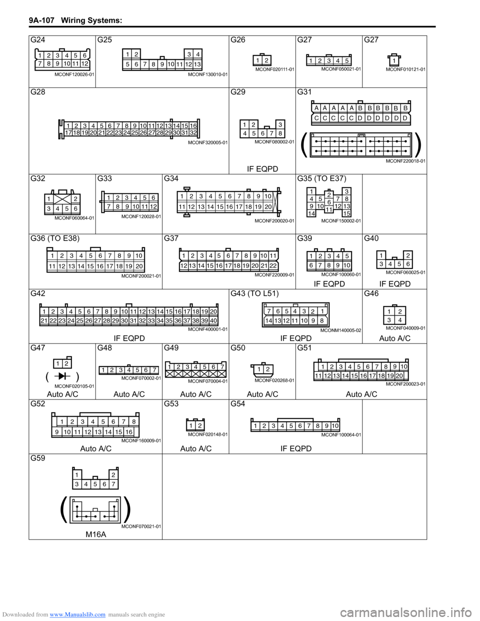
G24G25 G26G27 G27
G28 G29G31
IF EQPD
G32 G33G34 G35 (TO E37)
G36 (TO E38) G37G39G40
IF EQPD IF EQPD
G42 G43 (TO L51)G46
IF EQPD IF EQPDAuto A/C
G47 G48G49G50G51
Auto A/C Auto A/C Auto A/C Auto A/C Auto A/C
G52 G53G54
Auto A/C Auto A/CIF EQPD
G59
M16A
21
83
9 4
10 5
11 6
12
7
MCONF120026-01
710
56 12 34
8 9 11 12 13
MCONF130010-01
21
MCONF020111-01
12345MCONF050021-011
MCONF010121-01
1
17 2
18 3
19 4
20 5
21 6
22 7
23 8
24 9
25 10
26 11
27 12
28 13
29 14
30 15
31 16
32
MCONF320005-01
12 3
8
467 5
MCONF080002-01
AA A A A
BBBB
BB
CCC C CD DD D DD
()
MCONF220018-01
6543 21
MCONF060064-01
12345
78 11 6
12
910
MCONF120028-01
10
11 12 13 14 15 16 17 18 19 123456789
20
MCONF200020-01
14951071214
381315
2611
MCONF150002-01
10
11 12 13 14 15 16 17 18 19 123456789
20
MCONF200021-01
1234567891011
12 13 14 15 16 17 18 19 20 21 22
MCONF220009-01
54321
109876
MCONF100060-01
12
3456
MCONF060025-01
123456
212223242526
7
27
8
28
9
29
10
30
11
31
12
32
13
33
14
34
15
35
16
36
17
37
18
38
19
39
20
40
MCONF400001-01
7 654 3
21
14 13 12 11 10 9 8
MCONM140005-02
12
34
MCONF040009-01
1 2
( )MCONF020105-01
2
14 3657MCONF070002-01
1234567
MCONF070004-01
12
MCONF020268-01
12349105678
11121718192013141516MCONF200023-01
12345678
910151611121314
MCONF160009-01
21
MCONF020148-01
12345678910
MCONF100064-01
12
34567
()
MCONF070021-01
Page 1293 of 1496

Downloaded from www.Manualslib.com manuals search engine Lighting Systems: 9B-11
Front Fog Light Removal and Installation (If
Equipped)
S7RS0B9206014
Removal1) Disconnect negative (–) cable at battery.
2) Remove front bumper, and then remove front bumper guard from front bumper referring to “Front
Bumper and Rear Bumper Components in Section
9K”.
3) Disconnect coupler from fog light.
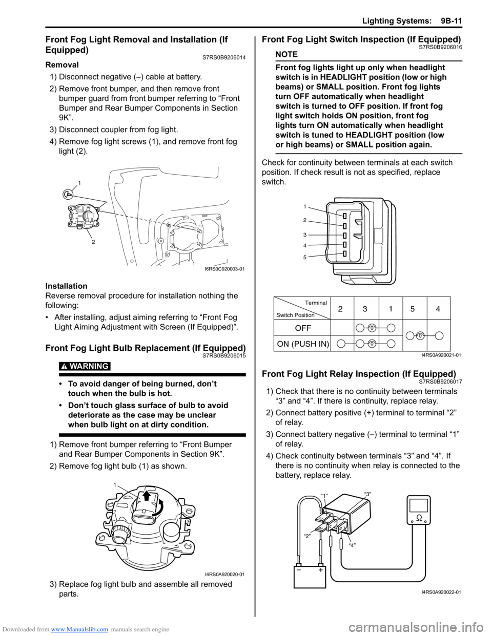
4) Remove fog light screws (1), and remove front fog light (2).
Installation
Reverse removal procedure for installation nothing the
following:
• After installing, adjust aimi ng referring to “Front Fog
Light Aiming Adjustment with Screen (If Equipped)”.
Front Fog Light Bulb Replacement (If Equipped)S7RS0B9206015
WARNING!
• To avoid danger of being burned, don’t touch when the bulb is hot.
• Don’t touch glass surface of bulb to avoid deteriorate as the case may be unclear
when bulb light on at dirty condition.
1) Remove front bumper referring to “Front Bumper and Rear Bumper Components in Section 9K”.
2) Remove fog light bulb (1) as shown.
3) Replace fog light bulb and assemble all removed parts.
Front Fog Light Switch Inspection (If Equipped)S7RS0B9206016
NOTE
Front fog lights light up only when headlight
switch is in HEADLIGHT position (low or high
beams) or SMALL position. Front fog lights
turn OFF automatically when headlight
switch is turned to OFF position. If front fog
light switch holds ON position, front fog
lights turn ON automa tically when headlight
switch is tuned to HEADLIGHT position (low
or high beams) or SMALL position again.
Check for continuity between terminals at each switch
position. If check result is not as specified, replace
switch.
Front Fog Light Relay Inspection (If Equipped)S7RS0B9206017
1) Check that there is no continuity between terminals “3” and “4”. If there is continuity, replace relay.
2) Connect battery positive (+ ) terminal to terminal “2”
of relay.
3) Connect battery negative (–) terminal to terminal “1” of relay.
4) Check continuity between terminals “3” and “4”. If there is no continuity when relay is connected to the
battery, replace relay.
1
2
I6RS0C920003-01
1
I4RS0A920020-01
1
2
3
4
5
Switch Position Terminal
ON (PUSH IN) 23
1
54
OFF
I4RS0A920021-01
“4”
“2” “1”
“3”
I4RS0A920022-01
Page 1298 of 1496
Downloaded from www.Manualslib.com manuals search engine 9C-3 Instrumentation / Driver Info. / Horn:
Auto Volume Control System Description (If Equipped)S7RS0B9301002
Function of auto volume control system is to vary sound volume according to changes of vehicle speed. How much
sound volume varies depends on selected level.
Reference correlation chart of vehicle speed and sound volume
[A]: Vehicle speed [D]: Deceleration
[B]: Sound volume [E]: Increase
[C]: Acceleration [F]: Decrease
[A][E]
[F]
[B] [E]
[F]
[C]
[D]
I6RS0B930004-01