2008 SUZUKI SWIFT stabilizer
[x] Cancel search: stabilizerPage 453 of 1496

Downloaded from www.Manualslib.com manuals search engine Front Suspension: 2B-20
Specifications
Tightening Torque SpecificationsS7RS0B2207001
NOTE
The specified tightening torque is also described in the following.
“Front Suspension Construction”
“Front Strut Assembly Components”
“Front Wheel Hub and Steering Knuckle Components”
“Front Suspension Frame, Stabilizer Bar and/or Bushings Components”
Reference:
For the tightening torque of fastener not specified in this section, refer to “Fasteners Information in Section 0A”.
Fastening part
Tightening torque
Note
N ⋅mkgf-mlb-ft
Tie-rod end lock nut 454.5 32.5 �)
Strut bracket nut 909.0 65.5 �) / �)
Brake hose mounting bolt 252.5 18.0 �)
Stabilizer joint nut 505.0 36.5 �) / �)
Strut nut 505.0 36.5 �)
Wheel nut 858.5 61.5 �) / �) / �)
Strut support lower nut 505.0 36.5 �)
Suspension control arm ball joint nut 606.0 43.5 �) / �)
Wheel speed sensor mounting bolt 111.1 8.0 �)
Caliper carrier bolt 858.5 61.5 �)
Drive shaft nut 200 20.0 145.0�)
Suspension control arm front bolt 959.5 68.0 �)
Suspension control arm rear bolt 959.5 68.0 �)
Stabilizer bar mounting bracket bolt 232.3 17.0 �)
Steering gear case mounting No.1 bolt 555.5 40.0 �)
Steering gear case mounting No.2 bolt 555.5 40.0 �)
Front suspension frame mounting bolt 150 15.0 108.5�)
Engine rear mounting bolt 555.5 40.0 �)
Steering shaft joint bolt 252.5 18.5 �)
Wheel bolt 858.5 61.5 �)
Page 466 of 1496

Downloaded from www.Manualslib.com manuals search engine 2C-12 Rear Suspension:
• Check noise and smooth rotation of wheel by rotating wheel. If it is defect ive, replace bearing.
Spindle Removal and InstallationS7RS0B2306014
Removal
1) Remove rear brake caliper assembly and brake disc. For details, refer to Step 2) to 4) of “Removal” under
“Rear Brake Disc Removal and Installation in
Section 4C”.
2) Remove rear wheel hub. For details, refer to Step 3) to 5) of “Removal” under “Rear Wheel Hub Removal
and Installation”.
3) Disconnect wheel speed sensor (1).
4) Remove brake disc dust cover (2) and spindle (3) from rear axle. Installation
1) Install brake disc dust cover (1), spindle (2) and new spindle bolts (3) and then tighten spindle bolts to
specified torque.
CAUTION!
Never reuse the removed rear spindle bolts.
Bolts are pre-coated wi th friction stabilizer.
Be sure to replace pre-coated bolt with a new
one, or bolt may loosen.
Tightening torque
Rear spindle bolt (a): 88 N·m (8.8 kgf-m, 64.0 lb-
ft)
2) Connect wheel speed sensor (4) and tighten wheel speed sensor bolt to specified torque.
Tightening torque
Wheel speed sensor bolt (b): 11 N·m (1.1 kgf-m,
8.0 lb-ft)
3) Install rear wheel hub re ferring to “Rear Wheel Hub
Removal and Installation”.
4) Install brake disc and rear brake caliper assembly referring to “Rear Brake Disc Removal and
Installation in Section 4C”.
5) Install wheel and tighten wheel nuts to specified torque.
Tightening torque
Wheel nut: 85 N·m (8.5 kgf-m, 61.5 lb-ft)
6) Adjust parking brake cable. For adjustment, see “Parking Brake Inspection and Adjustment in Section
4D”.
7) Perform brake test (foot brake and parking brake).
8) Check each installed part for fluid leakage.
I3RM0A230050-01
2
1 3
I6RS0B230015-01
1
(b)
4
2
3, (a)
I6RS0B230016-01
Page 482 of 1496

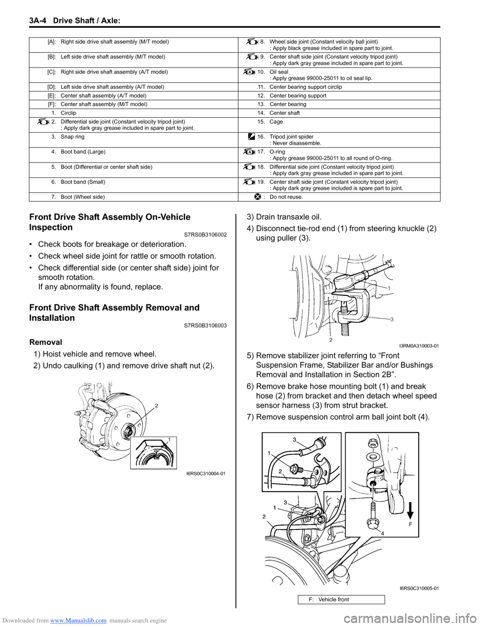
Downloaded from www.Manualslib.com manuals search engine 3A-4 Drive Shaft / Axle:
Front Drive Shaft Assembly On-Vehicle
Inspection
S7RS0B3106002
• Check boots for breakage or deterioration.
• Check wheel side joint for rattle or smooth rotation.
• Check differential side (or center shaft side) joint for smooth rotation.
If any abnormality is found, replace.
Front Drive Shaft Assembly Removal and
Installation
S7RS0B3106003
Removal
1) Hoist vehicle and remove wheel.
2) Undo caulking (1) and remove drive shaft nut (2). 3) Drain transaxle oil.
4) Disconnect tie-rod end (1) from steering knuckle (2)
using puller (3).
5) Remove stabilizer join t referring to “Front
Suspension Frame, Stabiliz er Bar and/or Bushings
Removal and Installati on in Section 2B”.
6) Remove brake hose mounting bolt (1) and break hose (2) from bracket and then detach wheel speed
sensor harness (3) from strut bracket.
7) Remove suspension contro l arm ball joint bolt (4).
[A]: Right side drive shaft assembly (M/T model) 8. Wheel side joint (Constant velocity ball joint)
: Apply black grease included in spare part to joint.
[B]: Left side drive shaft assembly (M/T model) 9. Center shaft side joint (Constant velocity tripod joint)
: Apply dark gray grease included in spare part to joint.
[C]: Right side drive shaft assembly (A/T model) 10. Oil seal
: Apply grease 99000-25011 to oil seal lip.
[D]: Left side drive shaft assembly (A/T model) 11. Center bearing support circlip
[E]: Center shaft assembly (A/T model) 12. Center bearing support
[F]: Center shaft assembly (M/T model) 13. Center bearing
1. Circlip 14. Center shaft
2. Differential side joint (Constant velocity tripod joint) : Apply dark gray grease included in spare part to joint. 15. Cage
3. Snap ring 16. Tripod joint spider
: Never disassemble.
4. Boot band (Large) 17. O-ring
: Apply grease 99000-25011 to all round of O-ring.
5. Boot (Differential or center shaft side) 18. Differential side joint (Constant velocity tripod joint)
: Apply dark gray grease included in spare part to joint.
6. Boot band (Small) 19. Center shaft side joint (Constant velocity tripod joint)
: Apply dark gray grease included is spare part to joint.
7. Boot (Wheel side) : Do not reuse.
I6RS0C310004-01
F: Vehicle front
I3RM0A310003-01
I6RS0C310005-01
Page 871 of 1496

Downloaded from www.Manualslib.com manuals search engine Steering General Diagnosis: 6A-2
Diagnostic Information and Procedures
Steering Symptom DiagnosisS7RS0B6104001
ConditionPossible cause Correction / Reference Item
Hard steering Tire not adequately inflated Inflate tires to proper pressure.
Malfunction of power steering system Check and correct.
Bind in tie-rod end ball studs or lower
ball joints Replace tie-rod end or front suspension arm.
Disturbed front wheel alignment Check and adjust front wheel alignment.
Bind in steering column Repair or replace steering column.
Rack and pinion adjustment Check and adjustment rack and pinion torque.
Too much play in steering Wheel bearings worn Replace wheel bearing.
Loose steering gear case bolts Tighten gear case bolts.
Faulty steering gear case assembly Replace steering gear case assembly.
Worn steering shaft joints Replace joint.
Worn tie-rod ends or tie-rod inside ball
joints Replace tie-rod end or tie-rod.
Worn lower ball joints Replace front suspension control arm.
Rack and pinion adjustment Check and adjustment rack and pinion torque.
Poor return ability Bind in tie-rod end ball studs Replace tie-rod end.
Bind in ball joints Replace front suspension control arm.
Bind in steering column Repair or replace steering column.
Disturbed front end alignment Check and adjust front end alignment.
Faulty steering gear case assembly Replace steering gear case assembly.
Tires not adequately inflated Adjust tire pressure.
Rack and pinion adjustment Check and adjustment rack and pinion torque.
Rack and pinion noise
(Rattle or chuckle) Loose steering gear case bolts
Tighten steering gear case bolts.
Rack and pinion adjustment Check and adjustment rack and pinion torque.
Faulty steering gear case assembly Replace steering gear case assembly.
Broken or other wise damaged wheel
bearing(s) Replace wheel bearing(s).
Wander or poor steering
stability Mismatched or uneven tires
Replace or inflate tires to proper pressure.
Loosen ball joints and tie-rod ends Replace suspension control arm or tie-rod end.
Faulty struts or mountings Replace strut or repair mounting.
Loose stabilizer bar Tighten or replace stabilizer bar or bush.
Broken or sagging springs Replace spring.
Rack and pinion adjustment Check and adjustment rack and pinion torque.
Disturbed front wheel alignment Check and adjust front wheel alignment.
Faulty steering gear case assembly Replace steering gear case assembly.
Erratic steering when
braking Worn wheel bearing(s)
Replace wheel bearing(s).
Broken or sagging spring(s) Replace coil spring(s).
Wheel tires are inflated unequally Inflate tires to proper pressure.
Disturbed front wheel alignment Check and adjust front wheel alignment.
Brakes not working in unison Check and repair brake system.
Leaking caliper Repair or replace caliper.
Warped discs Replace brake disc.
Badly worn brake pads Replace brake pads.
Page 924 of 1496

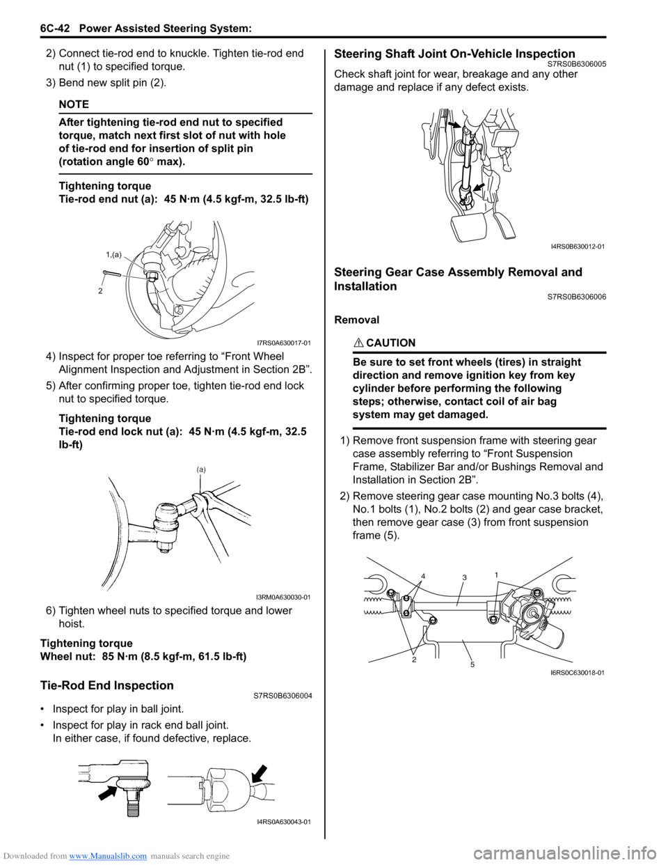
Downloaded from www.Manualslib.com manuals search engine 6C-42 Power Assisted Steering System:
2) Connect tie-rod end to knuckle. Tighten tie-rod end nut (1) to spec ified torque.
3) Bend new split pin (2).
NOTE
After tightening tie-rod end nut to specified
torque, match next first slot of nut with hole
of tie-rod end for insertion of split pin
(rotation angle 60 ° max).
Tightening torque
Tie-rod end nut (a): 45 N·m (4.5 kgf-m, 32.5 lb-ft)
4) Inspect for proper toe re ferring to “Front Wheel
Alignment Inspection and Adjustment in Section 2B”.
5) After confirming proper toe, tighten tie-rod end lock nut to specified torque.
Tightening torque
Tie-rod end lock nut (a): 45 N·m (4.5 kgf-m, 32.5
lb-ft)
6) Tighten wheel nuts to specified torque and lower hoist.
Tightening torque
Wheel nut: 85 N·m (8.5 kgf-m, 61.5 lb-ft)
Tie-Rod End InspectionS7RS0B6306004
• Inspect for play in ball joint.
• Inspect for play in rack end ball joint. In either case, if found defective, replace.
Steering Shaft Joint On-Vehicle InspectionS7RS0B6306005
Check shaft joint for wear, breakage and any other
damage and replace if any defect exists.
Steering Gear Case Assembly Removal and
Installation
S7RS0B6306006
Removal
CAUTION!
Be sure to set front wheels (tires) in straight
direction and remove ignition key from key
cylinder before performing the following
steps; otherwise, contact coil of air bag
system may get damaged.
1) Remove front suspension frame with steering gear case assembly referrin g to “Front Suspension
Frame, Stabilizer Bar and/ or Bushings Removal and
Installation in Section 2B”.
2) Remove steering gear case mounting No.3 bolts (4), No.1 bolts (1), No.2 bolts (2) and gear case bracket,
then remove gear case (3) from front suspension
frame (5).
2 1,(a)
I7RS0A630017-01
I3RM0A630030-01
I4RS0A630043-01
I4RS0B630012-01
25
3
14
I6RS0C630018-01
Page 925 of 1496

Downloaded from www.Manualslib.com manuals search engine Power Assisted Steering System: 6C-43
Installation1) Mount steering gear case (1) to front suspension frame (2) and tighten gear case mounting No.1 bolts
(3), No.2 bolts (4) and No .3 bolts (5) to specified
torque.
Tightening torque
Steering gear case mounting No.1 bolt (a): 55
N·m (5.5 kgf-m, 40.0 lb-ft)
Steering gear case mounting No.2 bolt (b): 55
N·m (5.5 kgf-m, 40.0 lb-ft)
Steering gear case mounting No.3 bolt (c): 40
N·m (4.0 kgf-m, 29.0 lb-ft)
2) Install earth cable (6) as shown in figure. Tightening torque
Earth cable bolt (d): 4.5 N·m (0.45 kgf-m, 3.5 lb-
ft)
3) Install grommet (1) whose projection (2) orients vehicle forward.
4) Install front suspension frame with steering gear case assembly referring to “Front Suspension
Frame, Stabilizer Bar and/or Bushings Removal and
Installation in Section 2B”.Steering Rack Boot InspectionS7RS0B6306007
Hoist vehicle.
Inspect each boot for tear. A torn boot allows entry of
dust and water which can cause wear to steering rack
and pinion to produce noise as well as rust to result in
malfunction of steering system.
Even if boot tear is small, replace with new one.
Also, check each boot for dent. If there is a dent, keep
boot in most compressed st ate for some seconds to
correct dent.
Boots should be visually inspected for any damage, dent
and tear during every periodical inspection at specified
intervals and whenever vehicle is hoisted for any other
purpose.
Tie-Rod / Rack Boot Removal and InstallationS7RS0B6306008
Removal
1) Remove steering gear case assembly referring to
“Steering Gear Case Assembly Removal and
Installation”.
2) For ease of adjustment after installation, make marking (1) of tie-rod end lock nut position of tie-rod
thread.
3) Loosen tie-rod end lock nut and remove tie-rod end.
4) Remove boot band (2) and clip (1).
5) Remove boot from tie-rod.
F: Vehicle forward
1 2
3, (a) 4, (b)
6, (d)
5, (c)
I6RS0C630019-02
12
F
I6RS0C630020-01
I2RH01630012-01
I4RS0A630044-01
IYSQ01630034-01