2008 SUZUKI SWIFT rod bearing
[x] Cancel search: rod bearingPage 434 of 1496
Downloaded from www.Manualslib.com manuals search engine 2B-1 Front Suspension:
Suspension
Front Suspension
General Description
Front Suspension ConstructionS7RS0B2201001
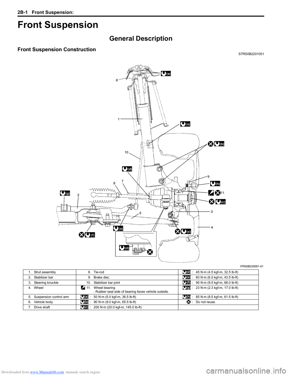
I7RS0B220001-01
1. Strut assembly8. Tie-rod : 45 N⋅m (4.5 kgf-m, 32.5 lb-ft)
2. Stabilizer bar 9. Brake disc : 60 N⋅m (6.0 kgf-m, 43.5 lb-ft)
3. Steering knuckle 10. Stabilizer bar joint : 95 N⋅m (9.5 kgf-m, 68.0 lb-ft)
4. Wheel 11. Wheel bearing
: Rubber seal side of bearing faces vehicle outside. : 23 N
⋅m (2.3 kgf-m, 17.0 lb-ft)
5. Suspension control arm : 50 N⋅m (5.0 kgf-m, 36.5 lb-ft) : 85 N⋅m (8.5 kgf-m, 61.5 lb-ft)
6. Vehicle body : 90 N⋅m (9.0 kgf-m, 65.5 lb-ft) : Do not reuse.
7. Drive shaft : 200 N⋅m (20.0 kgf-m, 145.0 lb-ft)
Page 436 of 1496
Downloaded from www.Manualslib.com manuals search engine 2B-3 Front Suspension:
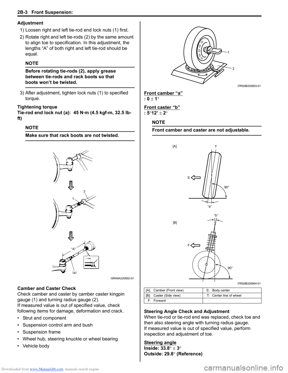
Adjustment1) Loosen right and left tie-rod end lock nuts (1) first.
2) Rotate right and left tie-rods (2) by the same amount to align toe to specification. In this adjustment, the
lengths “A” of both right and left tie-rod should be
equal.
NOTE
Before rotating tie-rods (2), apply grease
between tie-rods and rack boots so that
boots won’t be twisted.
3) After adjustment, tighten lock nuts (1) to specified torque.
Tightening torque
Tie-rod end lock nut (a): 45 N·m (4.5 kgf-m, 32.5 lb-
ft)
NOTE
Make sure that rack boots are not twisted.
Camber and Caster Check
Check camber and caster by camber caster kingpin
gauge (1) and turning radius gauge (2).
If measured value is out of specified value, check
following items for damage, deformation and crack.
• Strut and component
• Suspension control arm and bush
• Suspension frame
• Wheel hub, steering knuckle or wheel bearing
• Vehicle body Front camber “a”
: 0
± 1°
Front caster “b”
: 5 °12’ ± 2°
NOTE
Front camber and caster are not adjustable.
Steering Angle Check and Adjustment
When tie-rod or tie-rod end was replaced, check toe and
then also steering angle with turning radius gauge.
If measured value is out of specified value, perform
inspection and adjustment of toe.
Steering angle
Inside: 33.8 ° ± 3 °
Outside: 29.8 ° (Reference)
I3RH0A220002-01
[A]: Camber (Front view) S: Body center
[B]: Caster (Side view) T: Center line of wheel
F: Forward
2
1
I7RS0B220003-01
[B]
S T
90°
“a”
[A]
F
90°
“b”
I7RS0B220004-01
Page 437 of 1496
Downloaded from www.Manualslib.com manuals search engine Front Suspension: 2B-4
Reference Information
Side slip
When checked with side slip tester, side slip should
satisfy following specification.Side slip
0 to IN 3.0 mm/m (0 to IN 0.118 in/3.3 ft)
If side slip is greatly di
fferent, toe or front wheel
alignment may not be correct.
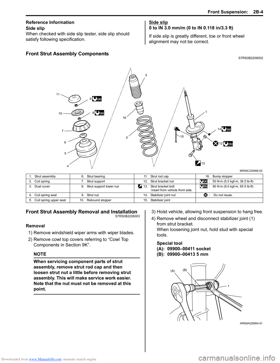
Front Strut Assembly ComponentsS7RS0B2206002
Front Strut Assembly Removal and InstallationS7RS0B2206003
Removal
1) Remove windshield wipe r arms with wiper blades.
2) Remove cowl top covers referring to “Cowl Top
Components in Section 9K”.
NOTE
When servicing component parts of strut
assembly, remove stru t rod cap and then
loosen strut nut a little before removing strut
assembly. This will make service work easier.
Note that the nut must not be removed at this
point.
3) Hoist vehicle, allowing front suspension to hang free.
4) Remove wheel and disconn ect stabilizer joint (1)
from strut bracket.
When loosening joint nu t, hold stud with special
tools.
Special tool
(A): 09900–00411 socket
(B): 09900–00413 5 mm
11 3
2 1
12
13
4
5
6
7
10
8(a)
(b)
9
(a)
14
15(a)
16
I6RS0C220006-02
1. Strut assembly
6. Strut bearing 11. Strut rod cap16. Bump stopper
2. Coil spring 7. Strut support 12. Strut bracket nut : 50 N⋅m (5.0 kgf-m, 36.5 lb-ft)
3. Dust cover 8. Strut support lower nut 13. Strut bracket bolt
:Insert from vehicle front side. : 90 N
⋅m (9.0 kgf-m, 65.5 lb-ft)
4. Coil spring seat 9. Strut nut 14. Stabilizer joint nut : Do not reuse.
5. Coil spring upper seat 10. Rebound stopper 15. Stabilizer joint
1
(A)
(B)
I4RS0A220004-01
Page 440 of 1496
Downloaded from www.Manualslib.com manuals search engine 2B-7 Front Suspension:
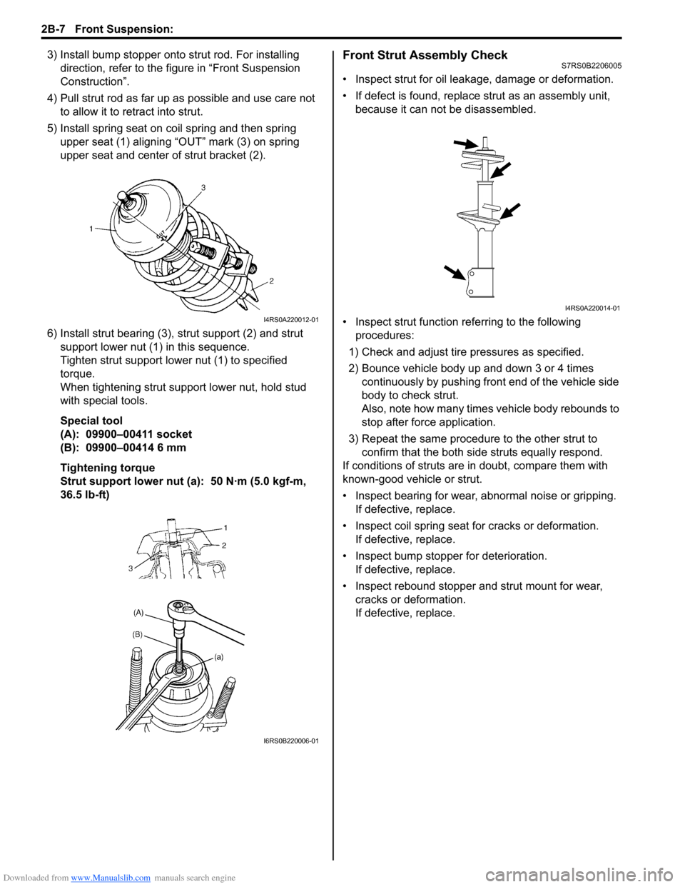
3) Install bump stopper onto strut rod. For installing
direction, refer to the figure in “Front Suspension
Construction”.
4) Pull strut rod as far up as possible and use care not to allow it to re tract into strut.
5) Install spring seat on coil spring and then spring upper seat (1) aligning “OUT” mark (3) on spring
upper seat and center of strut bracket (2).
6) Install strut bearing (3), strut support (2) and strut
support lower nut (1) in this sequence.
Tighten strut support lower nut (1) to specified
torque.
When tightening strut support lower nut, hold stud
with special tools.
Special tool
(A): 09900–00411 socket
(B): 09900–00414 6 mm
Tightening torque
Strut support lower nut (a): 50 N·m (5.0 kgf-m,
36.5 lb-ft)Front Strut Assembly CheckS7RS0B2206005
• Inspect strut for oil leakage, damage or deformation.
• If defect is found, replace strut as an assembly unit, because it can not be disassembled.
• Inspect strut function re ferring to the following
procedures:
1) Check and adjust tire pressures as specified.
2) Bounce vehicle body up and down 3 or 4 times continuously by pushing front end of the vehicle side
body to check strut.
Also, note how many times vehicle body rebounds to
stop after force application.
3) Repeat the same procedure to the other strut to confirm that the both side struts equally respond.
If conditions of struts are in doubt, compare them with
known-good vehicle or strut.
• Inspect bearing for wear, abnormal noise or gripping. If defective, replace.
• Inspect coil spring seat for cracks or deformation.
If defective, replace.
• Inspect bump stopper for deterioration. If defective, replace.
• Inspect rebound stopper and strut mount for wear, cracks or deformation.
If defective, replace.
I4RS0A220012-01
I6RS0B220006-01
I4RS0A220014-01
Page 441 of 1496
Downloaded from www.Manualslib.com manuals search engine Front Suspension: 2B-8
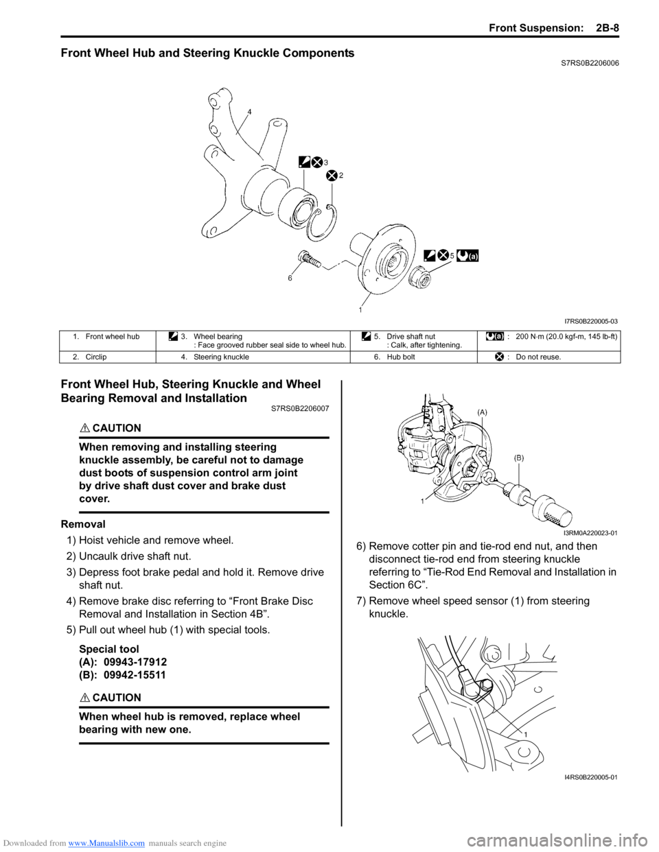
Front Wheel Hub and Steering Knuckle ComponentsS7RS0B2206006
Front Wheel Hub, Steering Knuckle and Wheel
Bearing Removal and Installation
S7RS0B2206007
CAUTION!
When removing and installing steering
knuckle assembly, be careful not to damage
dust boots of suspension control arm joint
by drive shaft dust cover and brake dust
cover.
Removal1) Hoist vehicle and remove wheel.
2) Uncaulk drive shaft nut.
3) Depress foot brake pedal and hold it. Remove drive shaft nut.
4) Remove brake disc referring to “Front Brake Disc Removal and Installa tion in Section 4B”.
5) Pull out wheel hub (1) with special tools.
Special tool
(A): 09943-17912
(B): 09942-15511
CAUTION!
When wheel hub is removed, replace wheel
bearing with new one.
6) Remove cotter pin and tie-rod end nut, and then disconnect tie-rod end from steering knuckle
referring to “Tie-Rod End Removal and Installation in
Section 6C”.
7) Remove wheel speed sensor (1) from steering knuckle.
I7RS0B220005-03
1. Front wheel hub 3. Wheel bearing
: Face grooved rubber seal side to wheel hub. 5. Drive shaft nut
: Calk, after tightening. : 200 N
⋅m (20.0 kgf-m, 145 lb-ft)
2. Circlip 4. Steering knuckle 6. Hub bolt: Do not reuse.
I3RM0A220023-01
1
I4RS0B220005-01
Page 479 of 1496

Downloaded from www.Manualslib.com manuals search engine Drive Shaft / Axle: 3A-1
Driveline / Axle
Drive Shaft / Axle
General Description
Front Drive Shaft ConstructionS7RS0B3101001
A constant velocity ball joint is used on the wheel side of both right and left side drive shaft assemblies. For A/T
vehicle, a tripod type constant velocity joint is used on the differential side and center shaft side. For M/T vehicle, a
double offset type constant velocity joint (DOJ) is used on the differential side and center shaft side. The drive shaft
can slide through the tripod joint or the double offset joint (DOJ) in the extension/contraction direction.
Component Location
Front Drive Shaft Assembly Components LocationS7RS0B3103001
I6RS0C310002-03
1. To transaxle 8. Ball stud washer : 45 N⋅m (4.5 kgf-m, 32.5 lb-ft)
2. Drive shaft assembly 9. Tie-rod end nut : 60 N⋅m (6.0 kgf-m, 43.5 lb-ft)
3. Tie-rod end 10. Ball stud bolt : 200 N⋅m (20.0 kgf-m, 145.0 lb-ft)
4. Center bearing support 11. Drive shaft nut
: After tightening nut, caulk nut securely. : 85 N
⋅m (8.5 kgf-m, 61.5 lb-ft)
5. Center shaft 12. Wheel nut : Do not reuse.
6. Center bearing support bolts 13. Drive shaft washer
7. Ball stud nut : 55 N⋅m (5.5 kgf-m, 40.0 lb-ft)
Page 482 of 1496
Downloaded from www.Manualslib.com manuals search engine 3A-4 Drive Shaft / Axle:
Front Drive Shaft Assembly On-Vehicle
Inspection
S7RS0B3106002
• Check boots for breakage or deterioration.
• Check wheel side joint for rattle or smooth rotation.
• Check differential side (or center shaft side) joint for smooth rotation.
If any abnormality is found, replace.
Front Drive Shaft Assembly Removal and
Installation
S7RS0B3106003
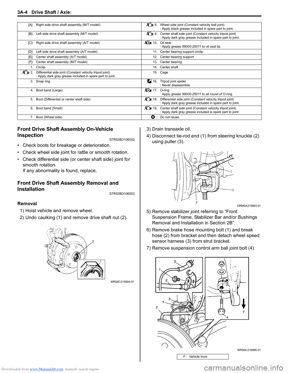
Removal
1) Hoist vehicle and remove wheel.
2) Undo caulking (1) and remove drive shaft nut (2). 3) Drain transaxle oil.
4) Disconnect tie-rod end (1) from steering knuckle (2)
using puller (3).
5) Remove stabilizer join t referring to “Front
Suspension Frame, Stabiliz er Bar and/or Bushings
Removal and Installati on in Section 2B”.
6) Remove brake hose mounting bolt (1) and break hose (2) from bracket and then detach wheel speed
sensor harness (3) from strut bracket.
7) Remove suspension contro l arm ball joint bolt (4).
[A]: Right side drive shaft assembly (M/T model) 8. Wheel side joint (Constant velocity ball joint)
: Apply black grease included in spare part to joint.
[B]: Left side drive shaft assembly (M/T model) 9. Center shaft side joint (Constant velocity tripod joint)
: Apply dark gray grease included in spare part to joint.
[C]: Right side drive shaft assembly (A/T model) 10. Oil seal
: Apply grease 99000-25011 to oil seal lip.
[D]: Left side drive shaft assembly (A/T model) 11. Center bearing support circlip
[E]: Center shaft assembly (A/T model) 12. Center bearing support
[F]: Center shaft assembly (M/T model) 13. Center bearing
1. Circlip 14. Center shaft
2. Differential side joint (Constant velocity tripod joint) : Apply dark gray grease included in spare part to joint. 15. Cage
3. Snap ring 16. Tripod joint spider
: Never disassemble.
4. Boot band (Large) 17. O-ring
: Apply grease 99000-25011 to all round of O-ring.
5. Boot (Differential or center shaft side) 18. Differential side joint (Constant velocity tripod joint)
: Apply dark gray grease included in spare part to joint.
6. Boot band (Small) 19. Center shaft side joint (Constant velocity tripod joint)
: Apply dark gray grease included is spare part to joint.
7. Boot (Wheel side) : Do not reuse.
I6RS0C310004-01
F: Vehicle front
I3RM0A310003-01
I6RS0C310005-01
Page 485 of 1496
Downloaded from www.Manualslib.com manuals search engine Drive Shaft / Axle: 3A-7
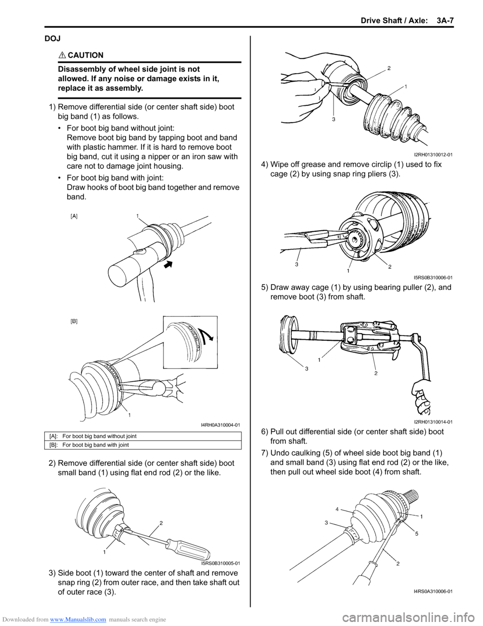
DOJ
CAUTION!
Disassembly of wheel side joint is not
allowed. If any noise or damage exists in it,
replace it as assembly.
1) Remove differential side (or center shaft side) boot big band (1) as follows.
• For boot big band without joint:Remove boot big band by tapping boot and band
with plastic hammer. If it is hard to remove boot
big band, cut it using a nipper or an iron saw with
care not to damage joint housing.
• For boot big band with joint: Draw hooks of boot big band together and remove
band.
2) Remove differential side (or center shaft side) boot small band (1) using flat end rod (2) or the like.
3) Side boot (1) toward the center of shaft and remove snap ring (2) from outer race, and then take shaft out
of outer race (3). 4) Wipe off grease and remove circlip (1) used to fix
cage (2) by using snap ring pliers (3).
5) Draw away cage (1) by using bearing puller (2), and remove boot (3) from shaft.
6) Pull out differential side (or center shaft side) boot from shaft.
7) Undo caulking (5) of wheel side boot big band (1) and small band (3) using flat end rod (2) or the like,
then pull out wheel side boot (4) from shaft.
[A]: For boot big band without joint
[B]: For boot big band with joint
I4RH0A310004-01
2
1
I5RS0B310005-01
I2RH01310012-01
I5RS0B310006-01
I2RH01310014-01
I4RS0A310006-01