2008 SUZUKI SWIFT power control door
[x] Cancel search: power control doorPage 1414 of 1496
Downloaded from www.Manualslib.com manuals search engine 10B-11 Body Electrical Control System:
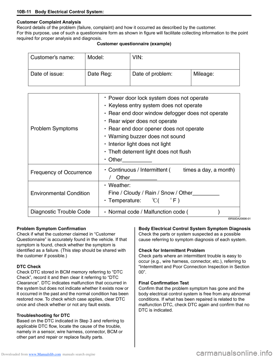
Customer Complaint Analysis
Record details of the problem (failure, complaint) and how it occurred as described by the customer.
For this purpose, use of such a questionnaire form as shown in figure will facilitate collectin g information to the point
required for proper analysis and diagnosis. Customer questionnaire (example)
Problem Symptom Confirmation
Check if what the custom er claimed in “Customer
Questionnaire” is accurately f ound in the vehicle. If that
symptom is found, check whether the symptom is
identified as a failure. (This step should be shared with
the customer if possible.)
DTC Check
Check DTC stored in BCM me mory referring to “DTC
Check”, record it and then clear it referring to “DTC
Clearance”. DTC indicates malfunction that occurred in
the system but does not indicate whether it exists now or
it occurred in the past and the normal condition has been
restored now. To check which case applies, clear DTC
once and check whether or not any fault exists.
Troubleshooting for DTC
Based on the DTC indicated in Step 3 and referring to
applicable DTC flow, locate the cause of the trouble,
namely in a sensor, wire harness, connector, BCM or
other part and repair or replace faulty parts. Body Electrical Control System Symptom Diagnosis
Check the parts or system
suspected as a possible
cause referring to symptom diagnosis of each system.
Check for Intermi ttent Problem
Check parts where an intermit tent trouble is easy to
occur (e.g., wire harness, connector, etc.), referring to
“Intermittent and Poor Connec tion Inspection in Section
00”.
Final Confirmation Test
Confirm that the problem symptom has gone and the
body electrical control system is free from any abnormal
conditions. If what has been repaired is related to the
malfunction DTC, check DTC again and confirm that no
DTC is indicated.
Customers name:
Model:
VIN:
Date of issue:
Date Reg:
Date of problem:
Mileage:
Problem Symptoms
Power door lock system does not operate
Keyless entry system does not operate
Rear end door window defogger does not operate
Rear wiper does not operate
Rear end door opener does not operate
Other
Frequency of Occurrence
Continuous / Intermittent ( times a day, a month)
/ Other
Environmental Condition
Weather:
Fine / Cloudy / Rain / Snow / Other
Temperature: (F )
Diagnostic Trouble Code Normal code / Malfunction code ( )
Warning buzzer does not sound
Interior light does not light
Theft deterrent light does not flush
I5RS0DA20006-01
Page 1436 of 1496
Downloaded from www.Manualslib.com manuals search engine 10B-33 Body Electrical Control System:
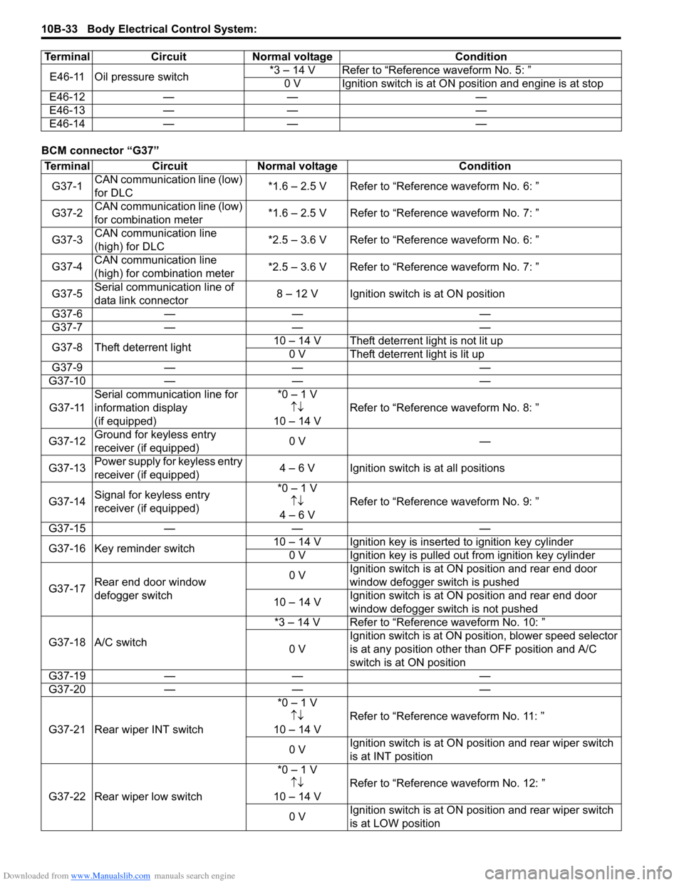
BCM connector “G37”E46-11 Oil pressure switch
*3 – 14 V Refer to “Reference waveform No. 5: ”
0 V Ignition switch is at ON position and engine is at stop
E46-12 — — —
E46-13 — — —
E46-14 — — —
Terminal Circuit Normal voltage Condition
Terminal
CircuitNormal voltage Condition
G37-1 CAN communication line (low)
for DLC *1.6 – 2.5 V Refer to “Reference waveform No. 6: ”
G37-2 CAN communication line (low)
for combination meter *1.6 – 2.5 V Refer to “Reference waveform No. 7: ”
G37-3 CAN communication line
(high) for DLC *2.5 – 3.6 V Refer to “Reference waveform No. 6: ”
G37-4 CAN communication line
(high) for combination meter *2.5 – 3.6 V Refer to “Reference waveform No. 7: ”
G37-5 Serial communication line of
data link connector 8 – 12 V Ignition switch is at ON position
G37-6 — — —
G37-7 — — —
G37-8 Theft deterrent light 10 – 14 V Theft deterrent light is not lit up
0 V Theft deterrent light is lit up
G37-9 — — —
G37-10 — — —
G37-11 Serial communication line for
information display
(if equipped) *0 – 1 V
↑↓
10 – 14 V Refer to “Reference
waveform No. 8: ”
G37-12 Ground for keyless entry
receiver (if equipped) 0 V
—
G37-13 Power supply for keyless entry
receiver (if equipped) 4 – 6 V Ignition switch is at all positions
G37-14 Signal for keyless entry
receiver (if equipped) *0 – 1 V
↑↓
4 – 6 V Refer to “Reference
waveform No. 9: ”
G37-15 — — —
G37-16 Key reminder switch 10 – 14 V Ignition key is inserted to ignition key cylinder
0 V Ignition key is pulled out from ignition key cylinder
G37-17 Rear end door window
defogger switch 0 V
Ignition switch is at ON
position and rear end door
window defogger switch is pushed
10 – 14 V Ignition switch is at ON
position and rear end door
window defogger switch is not pushed
G37-18 A/C switch *3 – 14 V Refer to “Reference waveform No. 10: ”
0 V Ignition switch is at ON pos
ition, blower speed selector
is at any position other than OFF position and A/C
switch is at ON position
G37-19 — — —
G37-20 — — —
G37-21 Rear wiper INT switch *0 – 1 V
↑↓
10 – 14 V Refer to “Reference
waveform No. 11: ”
0 V Ignition switch is at ON pos
ition and rear wiper switch
is at INT position
G37-22 Rear wiper low switch *0 – 1 V
↑↓
10 – 14 V Refer to “Reference
waveform No. 12: ”
0 V Ignition switch is at ON pos
ition and rear wiper switch
is at LOW position
Page 1437 of 1496
Downloaded from www.Manualslib.com manuals search engine Body Electrical Control System: 10B-34
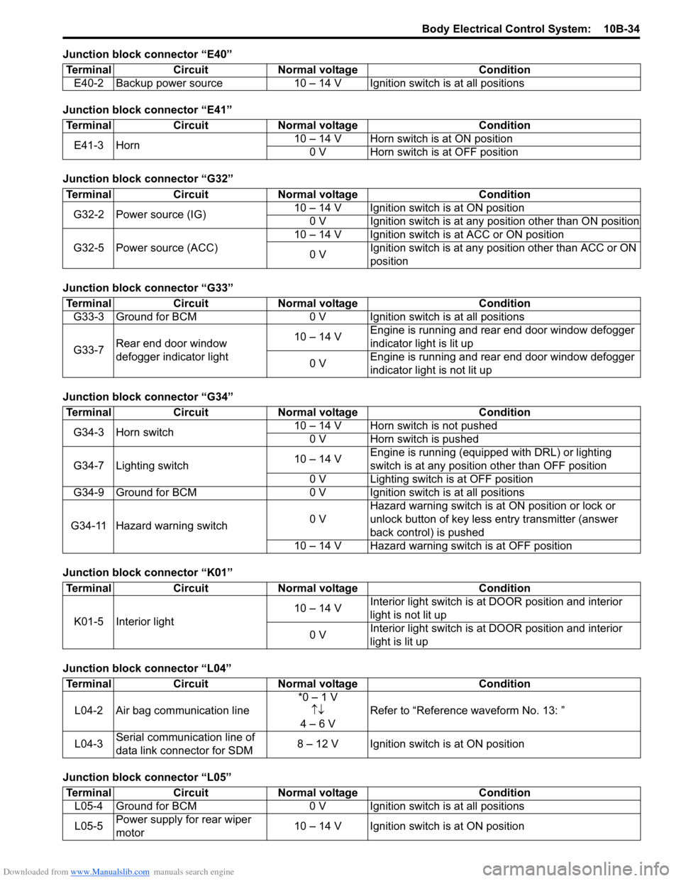
Junction block connector “E40”
Junction block connector “E41”
Junction block connector “G32”
Junction block connector “G33”
Junction block connector “G34”
Junction block connector “K01”
Junction block connector “L04”
Junction block connector “L05”Terminal Circuit Normal voltage Condition
E40-2 Backup power source 10 – 14 V Igni tion switch is at all positions
TerminalCircuitNormal voltage Condition
E41-3 Horn 10 – 14 V Horn switch is at ON position
0 V Horn switch is at OFF position
Terminal CircuitNormal voltage Condition
G32-2 Power source (IG) 10 – 14 V Ignition switch is at ON position
0 V Ignition switch is at any position other than ON position
G32-5 Power source (ACC) 10 – 14 V Ignition switch is at ACC or ON position
0 V Ignition switch is at any position other than ACC or ON
position
Terminal
CircuitNormal voltage Condition
G33-3 Ground for BCM 0 V Ignition switch is at all positions
G33-7 Rear end door window
defogger indicator light 10 – 14 V
Engine is running and rear end door window defogger
indicator light is lit up
0 V Engine is running and rear end door window defogger
indicator light is not lit up
Terminal
CircuitNormal voltage Condition
G34-3 Horn switch 10 – 14 V Horn switch is not pushed
0 V Horn switch is pushed
G34-7 Lighting switch 10 – 14 VEngine is running (equipped with DRL) or lighting
switch is at any position other than OFF position
0 V Lighting switch is at OFF position
G34-9 Ground for BCM 0 V Ignition switch is at all positions
G34-11 Hazard warning switch 0 VHazard warning switch is at
ON position or lock or
unlock button of key less entry transmitter (answer
back control) is pushed
10 – 14 V Hazard warning switch is at OFF position
Terminal CircuitNormal voltage Condition
K01-5 Interior light 10 – 14 V
Interior light switch is at
DOOR position and interior
light is not lit up
0 V Interior light switch is at
DOOR position and interior
light is lit up
Terminal CircuitNormal voltage Condition
L04-2 Air bag communication line *0 – 1 V
↑↓
4 – 6 V Refer to “Reference
waveform No. 13: ”
L04-3 Serial communication line of
data link connector for SDM 8 – 12 V Ignition switch is at ON position
Terminal
CircuitNormal voltage Condition
L05-4 Ground for BCM 0 V Ignition switch is at all positions
L05-5 Power supply for rear wiper
motor 10 – 14 V Ignition switch is at ON position
Page 1474 of 1496
Downloaded from www.Manualslib.com manuals search engine 10E-12 Keyless Start System:
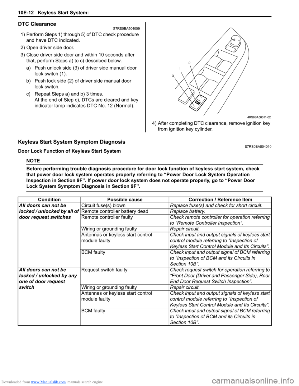
DTC ClearanceS7RS0BA504009
1) Perform Steps 1) through 5) of DTC check procedure and have DTC indicated.
2) Open driver side door.
3) Close driver side door and within 10 seconds after that, perform Steps a) to c) described below.
a) Push unlock side (3) of driver side manual door lock switch (1).
b) Push lock side (2) of driver side manual door lock switch.
c) Repeat Steps a) and b) 3 times. At the end of Step c), DTCs are cleared and key
indicator lamp indicates DTC No. 12 (Normal).
4) After completing DTC clearance, remove ignition key from ignition key cylinder.
Keyless Start System Symptom DiagnosisS7RS0BA504010
Door Lock Function of Keyless Start System
NOTE
Before performing trouble diagnosis procedure for door lock function of keyless start system, check
that power door lock system operates properly referring to “Power Door Lock System Operation
Inspection in Section 9F”. If power door lock system does not operate properly, go to “Power Door
Lock System Symptom Diagnosis in Section 9F”.
1
3 2
I4RS0BA50011-02
Condition
Possible cause Correction / Reference Item
All doors can not be
locked / unlocked by all of
door request switches Circuit fuse(s) blown
Replace fuse(s) and check for short circuit.
Remote controller battery dead Replace battery.
Remote controller faulty Check remote controller for operation referring
to “Remote Controller Inspection”.
Wiring or grounding faulty Repair circuit.
Antennas or keyless start control
module faulty Check input and output signals of keyless start
control module referring to “Inspection of
Keyless Start Control Mo
dule and Its Circuits”.
BCM faulty Check input and output signal of BCM referring
to “Inspection of BCM and its Circuits in
Section 10B”.
All doors can not be
locked / unlocked by any
one of door request
switch Request switch faulty
Check request switch for operation referring to
“Front Door (Driver and Passenger Side), Rear
End Door Request Switch Inspection”.
Wiring or grounding faulty Repair circuit.
Antennas or keyless start control
module faulty Check input and output signals of keyless start
control module referring to “Inspection of
Keyless Start Control Mo
dule and Its Circuits”.
BCM faulty Check input and output signal of BCM referring
to “Inspection of BCM and its Circuits in
Section 10B”.
Page 1477 of 1496
Downloaded from www.Manualslib.com manuals search engine Keyless Start System: 10E-15
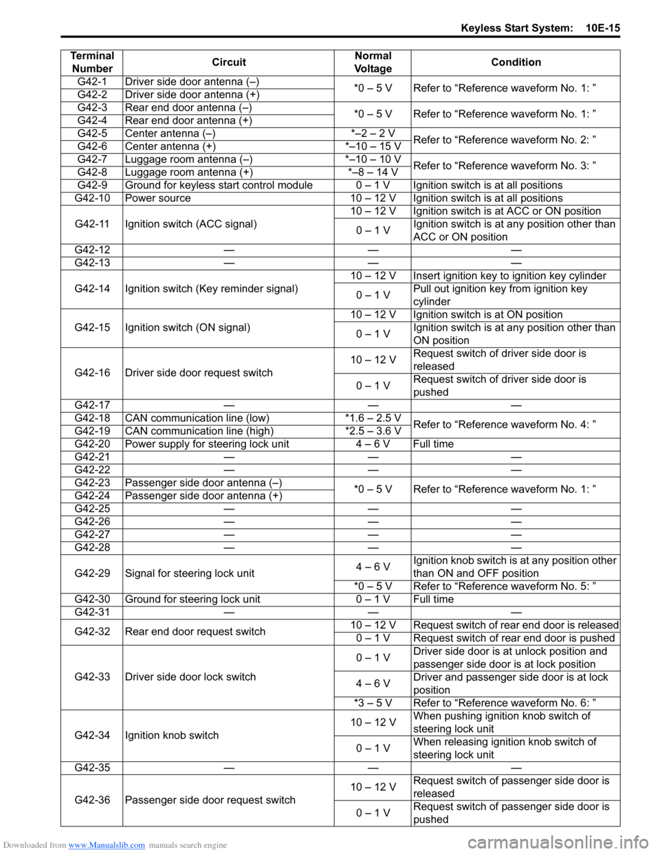
Terminal Number Circuit Normal
Vo l ta g e Condition
G42-1 Driver side door antenna (–) *0 – 5 V Refer to “Reference waveform No. 1: ”
G42-2 Driver side door antenna (+)
G42-3 Rear end door antenna (–) *0 – 5 V Refer to “Reference waveform No. 1: ”
G42-4 Rear end door antenna (+)
G42-5 Center antenna (–) *–2 – 2 V Refer to “Reference waveform No. 2: ”
G42-6 Center antenna (+) *–10 – 15 V
G42-7 Luggage room antenna (–) *–10 – 10 V Refer to “Reference waveform No. 3: ”
G42-8 Luggage room antenna (+) *–8 – 14 V
G42-9 Ground for keyless start control module 0 – 1 V Ignition switch is at all positions
G42-10 Power source 10 – 12 V Ignition switch is at all positions
G42-11 Ignition switch (ACC signal) 10 – 12 V Ignition switch is at ACC or ON position
0 – 1 V Ignition switch is at any position other than
ACC or ON position
G42-12 — — —
G42-13 — — —
G42-14 Ignition switch (Key reminder signal) 10 – 12 V Insert ignition key to ignition key cylinder
0 – 1 V Pull out ignition key from ignition key
cylinder
G42-15 Ignition switch (ON signal) 10 – 12 V Ignition switch is at ON position
0 – 1 V Ignition switch is at any position other than
ON position
G42-16 Driver side door request switch 10 – 12 V
Request switch of driver side door is
released
0 – 1 V Request switch of driver side door is
pushed
G42-17 — — —
G42-18 CAN communication line (low) *1.6 – 2.5 V Refer to “Reference waveform No. 4: ”
G42-19 CAN communication line (high) *2.5 – 3.6 V
G42-20 Power supply for steering lock unit 4 – 6 V Full time
G42-21 — — —
G42-22 — — —
G42-23 Passenger side door antenna (–) *0 – 5 V Refer to “Reference waveform No. 1: ”
G42-24 Passenger side door antenna (+)
G42-25 — — —
G42-26 — — —
G42-27 — — —
G42-28 — — —
G42-29 Signal for steering lock unit 4 – 6 VIgnition knob switch is at any position other
than ON and OFF position
*0 – 5 V Refer to “Reference waveform No. 5: ”
G42-30 Ground for steering lock unit 0 – 1 V Full time
G42-31 — — —
G42-32 Rear end door request switch 10 – 12 V Request switch of rear end door is released
0 – 1 V Request switch of rear end door is pushed
G42-33 Driver side door lock switch 0 – 1 V
Driver side door is at unlock position and
passenger side door is at lock position
4 – 6 V Driver and passenger side door is at lock
position
*3 – 5 V Refer to “Reference waveform No. 6: ”
G42-34 Ignition knob switch 10 – 12 V
When pushing ignition knob switch of
steering lock unit
0 – 1 V When releasing ignition knob switch of
steering lock unit
G42-35 — — —
G42-36 Passenger side door request switch 10 – 12 V
Request switch of passenger side door is
released
0 – 1 V Request switch of passenger side door is
pushed
Page 1481 of 1496
Downloaded from www.Manualslib.com manuals search engine Keyless Start System: 10E-19
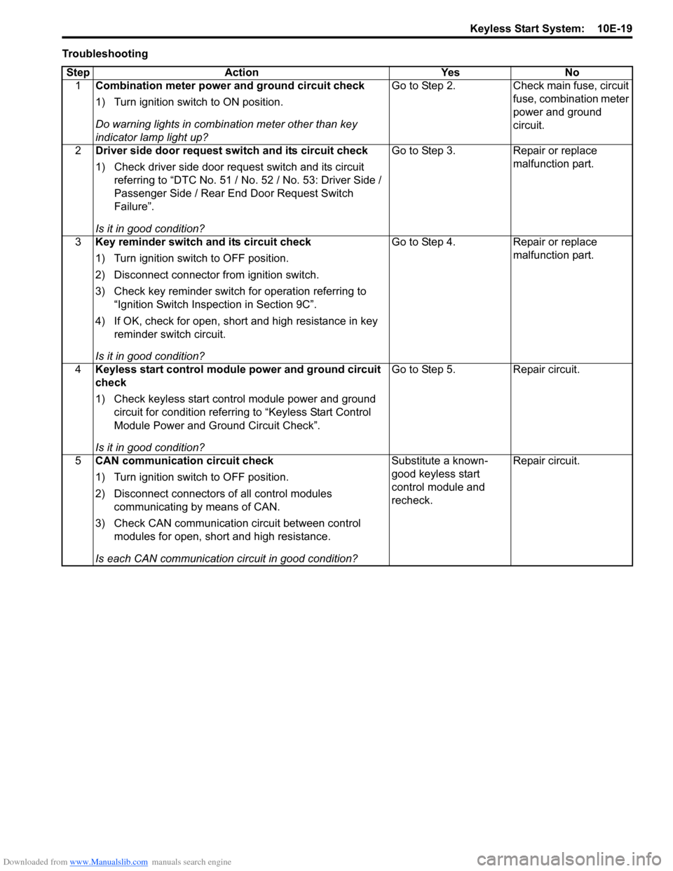
TroubleshootingStep Action Yes No 1 Combination meter power and ground circuit check
1) Turn ignition switch to ON position.
Do warning lights in combi nation meter other than key
indicator lamp light up? Go to Step 2. Check main fuse, circuit
fuse, combination meter
power and ground
circuit.
2 Driver side door request switch and its circuit check
1) Check driver side door request switch and its circuit
referring to “DTC No. 51 / No . 52 / No. 53: Driver Side /
Passenger Side / Rear End Door Request Switch
Failure”.
Is it in good condition? Go to Step 3. Repair or replace
malfunction part.
3 Key reminder switch and its circuit check
1) Turn ignition switch to OFF position.
2) Disconnect connector from ignition switch.
3) Check key reminder switch for operation referring to
“Ignition Switch Inspection in Section 9C”.
4) If OK, check for open, short and high resistance in key reminder switch circuit.
Is it in good condition? Go to Step 4. Repair or replace
malfunction part.
4 Keyless start control module power and ground circuit
check
1) Check keyless start control module power and ground
circuit for condition referrin g to “Keyless Start Control
Module Power and Ground Circuit Check”.
Is it in good condition? Go to Step 5. Repair circuit.
5 CAN communication circuit check
1) Turn ignition switch to OFF position.
2) Disconnect connectors of all control modules
communicating by means of CAN.
3) Check CAN communication circuit between control modules for open, short and high resistance.
Is each CAN communication circuit in good condition? Substitute a known-
good keyless start
control module and
recheck.
Repair circuit.
Page 1486 of 1496
Downloaded from www.Manualslib.com manuals search engine 10E-24 Keyless Start System:
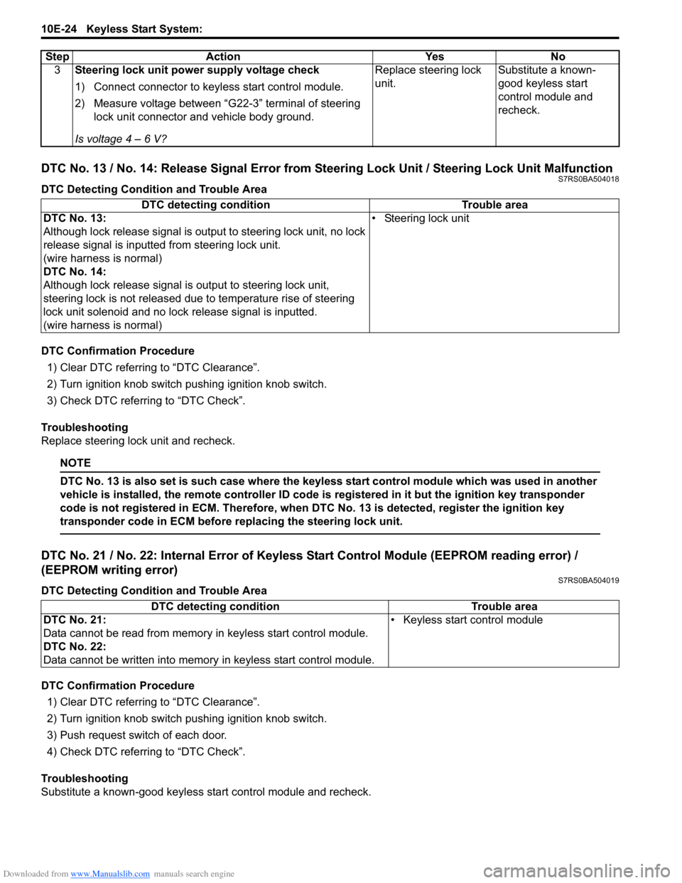
DTC No. 13 / No. 14: Release Signal Error from Steering Lock Unit / Steering Lock Unit MalfunctionS7RS0BA504018
DTC Detecting Condition and Trouble Area
DTC Confirmation Procedure1) Clear DTC referring to “DTC Clearance”.
2) Turn ignition knob switch pushing ignition knob switch.
3) Check DTC referring to “DTC Check”.
Troubleshooting
Replace steering lock unit and recheck.
NOTE
DTC No. 13 is also set is such case where the keyless start control module which was used in another
vehicle is installed, the remote controller ID code is registered in it but the ignition key transponder
code is not registered in ECM. Therefore, when DTC No. 13 is detected, register the ignition key
transponder code in ECM before replacing the steering lock unit.
DTC No. 21 / No. 22: Internal Error of Keyle ss Start Control Module (EEPROM reading error) /
(EEPROM writing error)
S7RS0BA504019
DTC Detecting Condition and Trouble Area
DTC Confirmation Procedure
1) Clear DTC referring to “DTC Clearance”.
2) Turn ignition knob switch pushing ignition knob switch.
3) Push request switch of each door.
4) Check DTC referring to “DTC Check”.
Troubleshooting
Substitute a known-good keyless start control module and recheck. 3
Steering lock unit power supply voltage check
1) Connect connector to keyl ess start control module.
2) Measure voltage between “G22-3” terminal of steering lock unit connector and vehicle body ground.
Is voltage 4 – 6 V? Replace steering lock
unit.
Substitute a known-
good keyless start
control module and
recheck.
Step Action Yes No
DTC detecting condition
Trouble area
DTC No. 13:
Although lock release signal is ou tput to steering lock unit, no lock
release signal is inputted from steering lock unit.
(wire harness is normal)
DTC No. 14:
Although lock release signal is output to steering lock unit,
steering lock is not released due to temperature rise of steering
lock unit solenoid and no lock release signal is inputted.
(wire harness is normal) • Steering lock unit
DTC detecting condition Trouble area
DTC No. 21:
Data cannot be read from memory in keyless start control module.
DTC No. 22:
Data cannot be written into memory in keyless start control module.• Keyless start control module
Page 1490 of 1496
Downloaded from www.Manualslib.com manuals search engine 10E-28 Keyless Start System:
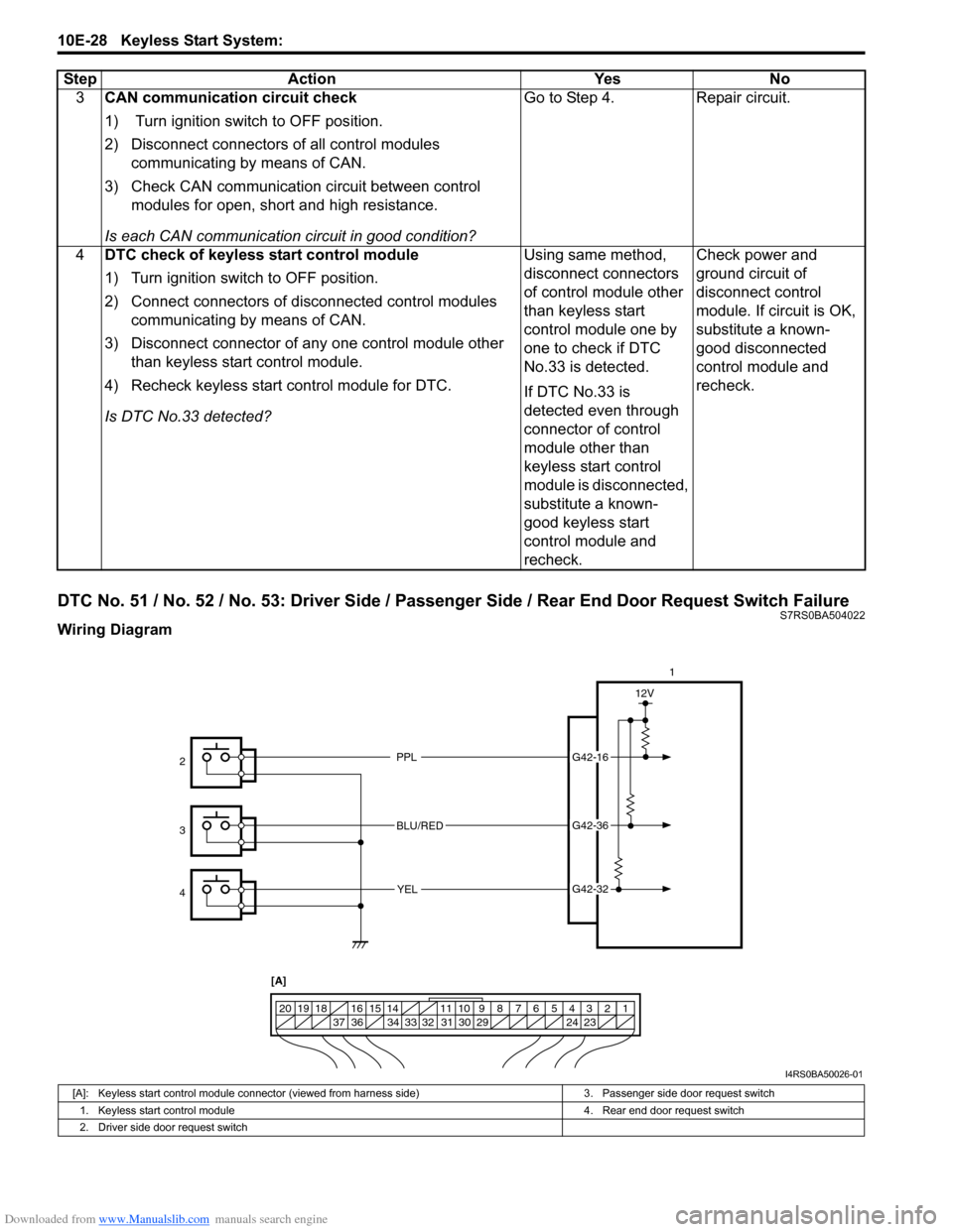
DTC No. 51 / No. 52 / No. 53: Driver Side / Passenger Side / Rear End Door Request Switch FailureS7RS0BA504022
Wiring Diagram3
CAN communication circuit check
1) Turn ignition switch to OFF position.
2) Disconnect connectors of all control modules
communicating by means of CAN.
3) Check CAN communication circuit between control modules for open, short and high resistance.
Is each CAN communication circuit in good condition? Go to Step 4. Repair circuit.
4 DTC check of keyless start control module
1) Turn ignition switch to OFF position.
2) Connect connectors of disconnected control modules
communicating by means of CAN.
3) Disconnect connector of any one control module other than keyless start control module.
4) Recheck keyless start control module for DTC.
Is DTC No.33 detected? Using same method,
disconnect connectors
of control module other
than keyless start
control module one by
one to check if DTC
No.33 is detected.
If DTC No.33 is
detected even through
connector of control
module other than
keyless start control
module is disconnected,
substitute a known-
good keyless start
control module and
recheck.Check power and
ground circuit of
disconnect control
module. If circuit is OK,
substitute a known-
good disconnected
control module and
recheck.
Step
Action YesNo
PPL
BLU/RED YELG42-16
G42-36
G42-32
12V
1234567891011
141516
36 34 33 32 31 30 29 24 23
37
181920
1
2
3
4 [A]
I4RS0BA50026-01
[A]: Keyless start control module connector (viewed from harness side) 3. Passenger side door request switch
1. Keyless start control module 4. Rear end door request switch
2. Driver side door request switch