2008 SUZUKI SWIFT intake manifold
[x] Cancel search: intake manifoldPage 115 of 1496
Downloaded from www.Manualslib.com manuals search engine Engine General Information and Diagnosis: 1A-65
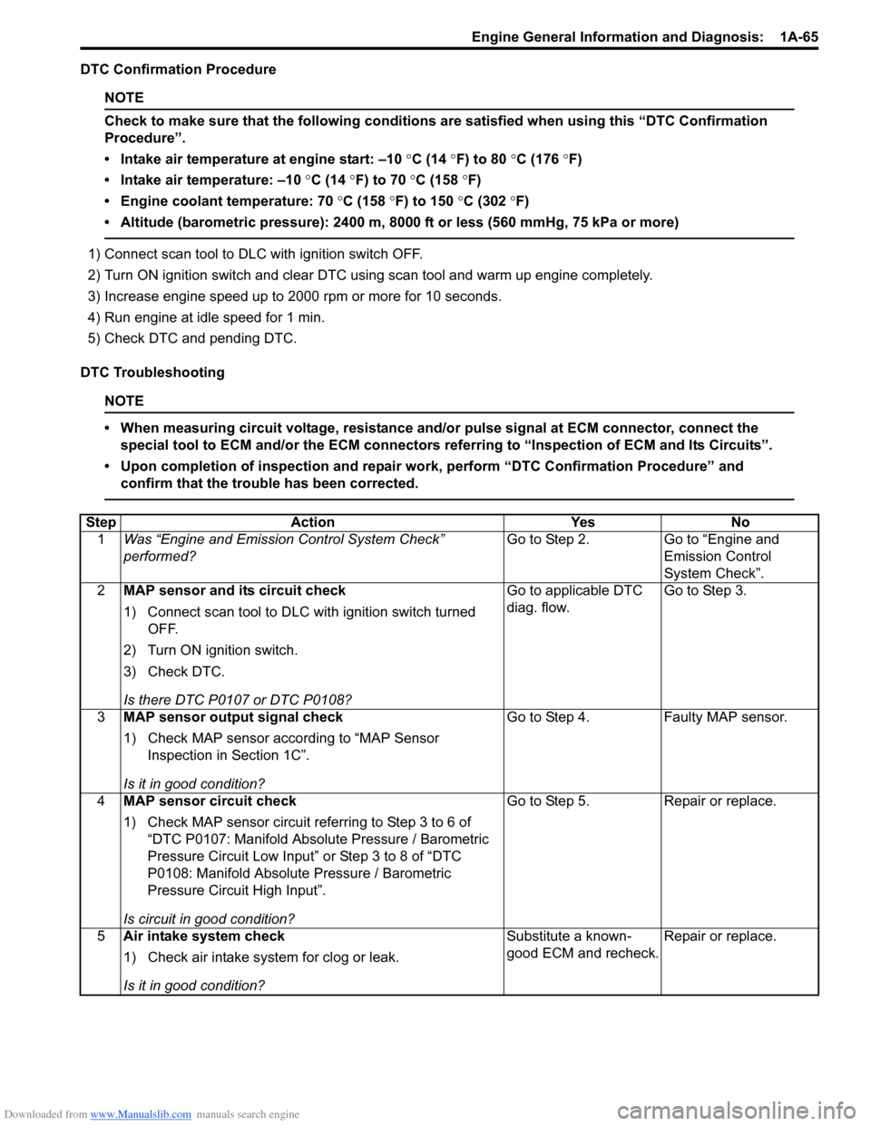
DTC Confirmation Procedure
NOTE
Check to make sure that the following conditions are satisfied when using this “DTC Confirmation
Procedure”.
• Intake air temperature at engine start: –10 °C (14 ° F) to 80 °C (176 °F)
• Intake air temperature: –10 °C (14 °F) to 70 °C (158 °F)
• Engine coolant temperature: 70 °C (158 °F) to 150 °C (302 °F)
• Altitude (barometric pressure): 2400 m, 8000 ft or less (560 mmHg, 75 kPa or more)
1) Connect scan tool to DLC with ignition switch OFF.
2) Turn ON ignition switch and clear DTC using scan tool and warm up engine completely.
3) Increase engine speed up to 2000 rpm or more for 10 seconds.
4) Run engine at idle speed for 1 min.
5) Check DTC and pending DTC.
DTC Troubleshooting
NOTE
• When measuring circuit voltage, resistance and/ or pulse signal at ECM connector, connect the
special tool to ECM and/or the ECM connectors re ferring to “Inspection of ECM and Its Circuits”.
• Upon completion of inspection and repair work, perform “DTC Confirmation Procedure” and confirm that the trouble has been corrected.
Step Action YesNo
1 Was “Engine and Emission Control System Check”
performed? Go to Step 2.
Go to “Engine and
Emission Control
System Check”.
2 MAP sensor and its circuit check
1) Connect scan tool to DLC with ignition switch turned
OFF.
2) Turn ON ignition switch.
3) Check DTC.
Is there DTC P0107 or DTC P0108? Go to applicable DTC
diag. flow.
Go to Step 3.
3 MAP sensor output signal check
1) Check MAP sensor acco rding to “MAP Sensor
Inspection in Section 1C”.
Is it in good condition? Go to Step 4.
Faulty MAP sensor.
4 MAP sensor circuit check
1) Check MAP sensor circuit referring to Step 3 to 6 of
“DTC P0107: Manifold Absolute Pressure / Barometric
Pressure Circuit Low Input” or Step 3 to 8 of “DTC
P0108: Manifold Absolute Pressure / Barometric
Pressure Circuit High Input”.
Is circuit in good condition? Go to Step 5.
Repair or replace.
5 Air intake system check
1) Check air intake system for clog or leak.
Is it in good condition? Substitute a known-
good ECM and recheck.
Repair or replace.
Page 116 of 1496
Downloaded from www.Manualslib.com manuals search engine 1A-66 Engine General Information and Diagnosis:
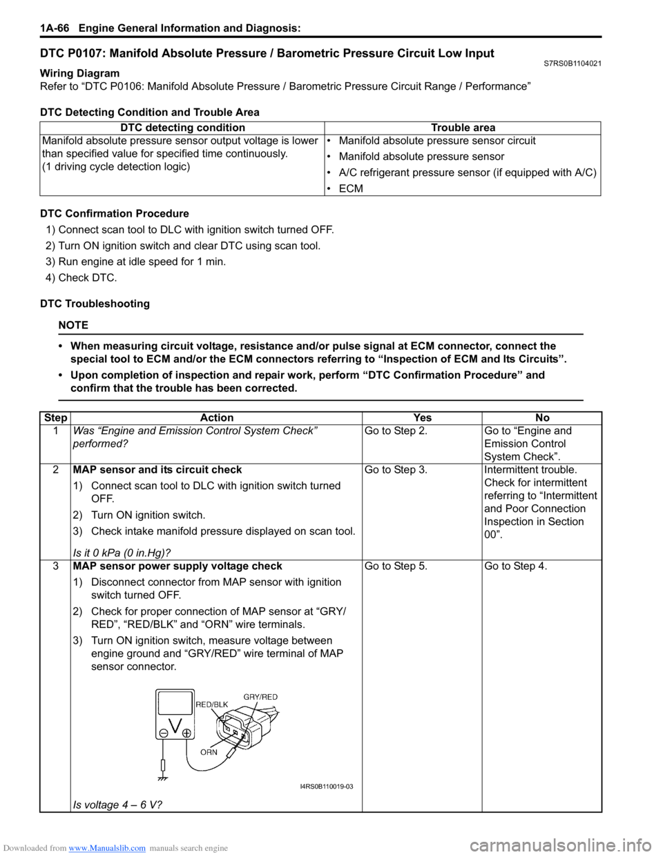
DTC P0107: Manifold Absolute Pressure / Barometric Pressure Circuit Low InputS7RS0B1104021
Wiring Diagram
Refer to “DTC P0106: Manifold Absolute Pressure / Barometric Pressure Circuit Range / Performance”
DTC Detecting Condition and Trouble Area
DTC Confirmation Procedure 1) Connect scan tool to DLC with ignition switch turned OFF.
2) Turn ON ignition switch and clear DTC using scan tool.
3) Run engine at idle speed for 1 min.
4) Check DTC.
DTC Troubleshooting
NOTE
• When measuring circuit voltage, resistance and/ or pulse signal at ECM connector, connect the
special tool to ECM and/or the ECM connectors re ferring to “Inspection of ECM and Its Circuits”.
• Upon completion of inspection and repair work, perform “DTC Confirmation Procedure” and confirm that the trouble has been corrected.
DTC detecting condition Trouble area
Manifold absolute pressure se nsor output voltage is lower
than specified value for s pecified time continuously.
(1 driving cycle detection logic) • Manifold absolute pressure sensor circuit
• Manifold absolute pressure sensor
• A/C refrigerant pressure sensor (if equipped with A/C)
•ECM
Step
Action YesNo
1 Was “Engine and Emission Control System Check”
performed? Go to Step 2.
Go to “Engine and
Emission Control
System Check”.
2 MAP sensor and its circuit check
1) Connect scan tool to DLC with ignition switch turned
OFF.
2) Turn ON ignition switch.
3) Check intake manifold pressure displayed on scan tool.
Is it 0 kPa (0 in.Hg)? Go to Step 3.
Intermittent trouble.
Check for intermittent
referring to “Intermittent
and Poor Connection
Inspection in Section
00”.
3 MAP sensor power supply voltage check
1) Disconnect connector from MAP sensor with ignition
switch turned OFF.
2) Check for proper connection of MAP sensor at “GRY/ RED”, “RED/BLK” and “ORN” wire terminals.
3) Turn ON ignition switch, measure voltage between engine ground and “GRY/RED” wire terminal of MAP
sensor connector.
Is voltage 4 – 6 V? Go to Step 5.
Go to Step 4.
I4RS0B110019-03
Page 118 of 1496
Downloaded from www.Manualslib.com manuals search engine 1A-68 Engine General Information and Diagnosis:
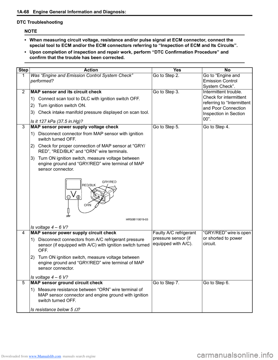
DTC Troubleshooting
NOTE
• When measuring circuit voltage, resistance and/or pulse signal at ECM connector, connect the
special tool to ECM and/or the ECM connectors re ferring to “Inspection of ECM and Its Circuits”.
• Upon completion of inspection and repair work, perform “DTC Confirmation Procedure” and confirm that the trouble has been corrected.
Step Action YesNo
1 Was “Engine and Emission Control System Check”
performed? Go to Step 2.
Go to “Engine and
Emission Control
System Check”.
2 MAP sensor and its circuit check
1) Connect scan tool to DLC with ignition switch OFF.
2) Turn ignition switch ON.
3) Check intake manifold pressure displayed on scan tool.
Is it 127 kPa (37.5 in.Hg)? Go to Step 3.
Intermittent trouble.
Check for intermittent
referring to “Intermittent
and Poor Connection
Inspection in Section
00”.
3 MAP sensor power supply voltage check
1) Disconnect connector from MAP sensor with ignition
switch turned OFF.
2) Check for proper connection of MAP sensor at “GRY/ RED”, “RED/BLK” and “ORN” wire terminals.
3) Turn ON ignition switch, measure voltage between engine ground and “GRY/RED” wire terminal of MAP
sensor connector.
Is voltage 4 – 6 V? Go to Step 5.
Go to Step 4.
4 MAP sensor power supply circuit check
1) Disconnect connectors from A/C refrigerant pressure
sensor (if equipped with A/C) with ignition switch turned
OFF.
2) Turn ON ignition switch, measure voltage between engine ground and “GRY/RED” wire terminal of MAP
sensor connector.
Is voltage 4 – 6 V? Faulty A/C refrigerant
pressure sensor (if
equipped with A/C).
“GRY/RED” wire is open
or shorted to power
circuit.
5 MAP sensor ground circuit check
1) Measure resistance between “ORN” wire terminal of
MAP sensor connector and engine ground with ignition
switch turned OFF.
Is resistance below 5
Ω? Go to Step 7.
Go to Step 6.
I4RS0B110019-03
Page 166 of 1496
Downloaded from www.Manualslib.com manuals search engine 1A-116 Engine General Information and Diagnosis:
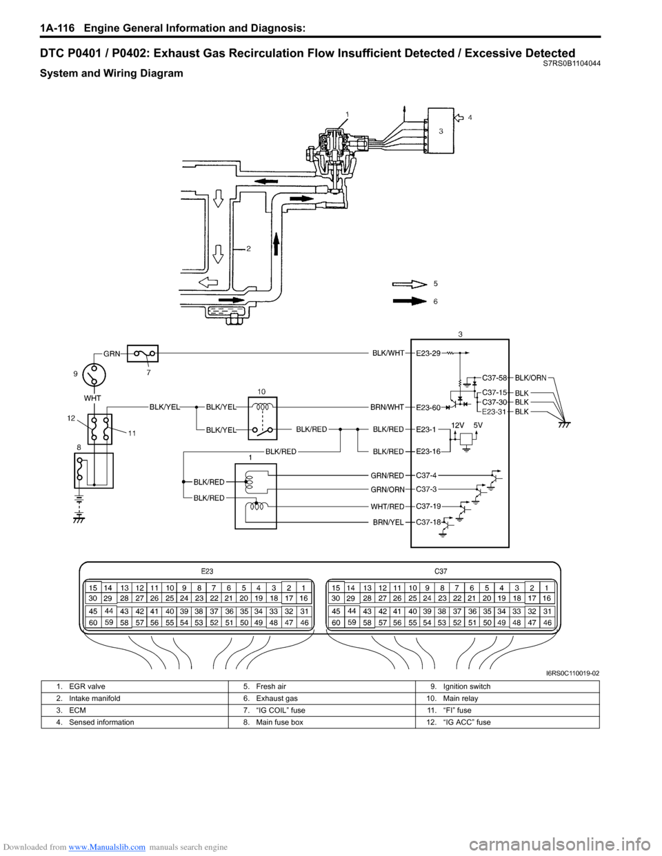
DTC P0401 / P0402: Exhaust Gas Recirculation Flow Insufficient Detected / Excessive DetectedS7RS0B1104044
System and Wiring Diagram
I6RS0C110019-02
1. EGR valve5. Fresh air 9. Ignition switch
2. Intake manifold 6. Exhaust gas10. Main relay
3. ECM 7. “IG COIL” fuse11. “FI” fuse
4. Sensed information 8. Main fuse box12. “IG ACC” fuse
Page 167 of 1496
Downloaded from www.Manualslib.com manuals search engine Engine General Information and Diagnosis: 1A-117
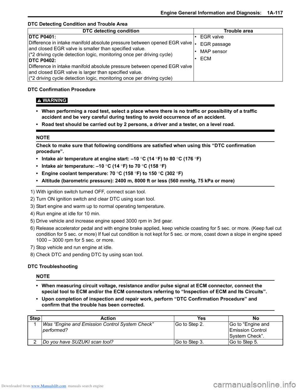
DTC Detecting Condition and Trouble Area
DTC Confirmation Procedure
WARNING!
• When performing a road test, select a place where there is no traffic or possibility of a traffic accident and be very careful during testing to avoid occurrence of an accident.
• Road test should be carried out by 2 persons, a driver and a tester, on a level road.
NOTE
Check to make sure that following conditions ar e satisfied when using this “DTC confirmation
procedure”.
• Intake air temperature at engine start: –10 °C (14 ° F) to 80 °C (176 °F)
• Intake air temperature: –10 °C (14 °F) to 70 °C (158 °F)
• Engine coolant temperature: 70 °C (158 °F) to 150 °C (302 °F)
• Altitude (barometric pressure): 2400 m, 8000 ft or less (560 mmHg, 75 kPa or more)
1) With ignition switch turned OFF, connect scan tool.
2) Turn ON ignition switch and clear DTC using scan tool.
3) Start engine and warm up to normal operating temperature.
4) Run engine at idle for 10 min.
5) Drive vehicle and increase engine speed 3000 rpm in 3rd gear.
6) Release accelerator pedal and with engine brake applied, keep vehicle coasting for 5 sec. or more. (Keep fuel cut condition for 5 sec. or more) If fuel cut condition is not ke pt for 5 sec. or more, coast down a slope in engine speed
1000 – 3000 rpm for 5 sec. or more.
7) Stop vehicle and run engine at idle.
8) Check DTC and pending DTC by using scan tool.
DTC Troubleshooting
NOTE
• When measuring circuit voltage, resistance and/ or pulse signal at ECM connector, connect the
special tool to ECM and/or the ECM connectors re ferring to “Inspection of ECM and Its Circuits”.
• Upon completion of inspection and repair work, perform “DTC Confirmation Procedure” and confirm that the trouble has been corrected.
DTC detecting condition Trouble area
DTC P0401:
Difference in intake manifold absolute pressure between opened EGR valve
and closed EGR valve is smaller than specified value.
(*2 driving cycle detection logic, monitoring once per driving cycle)
DTC P0402:
Difference in intake manifold absolute pressure between opened EGR valve
and closed EGR valve is la rger than specified value.
(*2 driving cycle detection logic, monitoring once per driving cycle) •EGR valve
• EGR passage
• MAP sensor
•ECM
Step
Action YesNo
1 Was “Engine and Emission Control System Check”
performed? Go to Step 2.
Go to “Engine and
Emission Control
System Check”.
2 Do you have SUZUKI scan tool? Go to Step 3.Go to Step 5.
Page 223 of 1496

Downloaded from www.Manualslib.com manuals search engine Engine General Information and Diagnosis: 1A-173
DTC P2227 / P2228 / P2229: Barometric Pressure Circuit MalfunctionS7RS0B1104078
DTC P2227: Barometric Pressure Circuit Range / Performance
DTC P2228: Barometric Pressure Circuit Low
DTC P2229: Barometric Pressure Circuit High
System Description
Barometric pressure sensor is installed in ECM.
DTC Detecting Condition and Trouble Area6
Wire harness check
1) Disconnect connectors from ECM with ignition switch
turned OFF.
2) Check for proper connection of ECM connector at “E23- 37”, “E23-52”, “E23-36” and “E23-51” terminals.
3) If OK, measure resistance between “GRN” wire terminal of APP sensor connector and vehicle body ground,
between “YEL” wire terminal of APP sensor connector
and vehicle body ground.
Is each resistance infinity? Go to Step 7. “GRN” wire or “YEL”
wire is shorted to other
circuit.
7 Wire harness check
1) Turn ON ignition switch.
2) Measure voltage between “E23-37” terminal of ECM
connector and engine ground, between “E23-36”
terminal of ECM connector and engine ground.
Is each voltage 0 V? Go to Step 8. “GRN” wire or “YEL”
wire is shorted to other
circuit.
8 APP sensor check
1) Check APP sensor referring to “APP Sensor Assembly
Inspection in Section 1C”.
Is output voltage within specified value? Substitute a known-
good ECM and recheck.
Replace APP sensor
assembly.
Step Action Yes No
DTC detecting condition
Trouble area
DTC P2227:
Difference of barometric pressure value and intake manifold
pressure value is higher than specified value while engine
cranking.
(*2 driving cycle detection logic, monitoring once par driving cycle) • Manifold absolute pressure sensor
performance problem
• Barometric pressure sensor in ECM
DTC P2228:
Barometric pressure signal less than specified value is detected.
(1 driving cycle detection logic) • Barometric pressure sensor in ECM
DTC P2229:
Barometric pressure signal more than specified value is detected.
(1 driving cycle detection logic)
Page 269 of 1496

Downloaded from www.Manualslib.com manuals search engine Aux. Emission Control Devices: 1B-2
EVAP Canister Purge Valve and Its Circuit
Inspection
S7RS0B1206002
WARNING!
Do not apply vacuum by mouth; otherwise
harmful fuel vapor can be breathed in.
CAUTION!
Do not apply vacuum more than –86 kPa (–
12.47 psi); otherwise EVAP canister purge
valve could be damaged.
1) Prepare to operate EVAP canister purge valve as follows.
a) When using SUZUKI scan tool:
i) Connect SUZUKI scan tool to DLC (1) with ignition switch turned OFF and disconnect
purge valve vacuum hoses from intake
manifold and EVAP canister.
ii) Turn ON ignition switch, clear DTC and select “MISC TEST” mode on SUZUKI scan
tool.
Special tool
(A): SUZUKI scan tool b) When not using SUZUKI scan tool:
NOTE
Before performed this check, be sure to read
the “Precautions of ECM Circuit Inspection in
Section 1A”.
i) Disconnect purge valve vacuum hoses from
intake manifold and EVAP canister.
ii) Remove ECM from it s bracket referring to
“ECM Removal and Inst allation in Section
1C”.
iii) Connect special tool between ECM and ECM connector referring to “Inspection of ECM
and Its Circuits in Section 1A”
iv) Turn ON ignition switch. Using service wire, ground “C37-29” terminal
circuit of special tool (valve ON: “B”) and
unground it (valve OFF: “A”).
2) Check purge valve for operation and vacuum passage for clog when valve is switched ON and
OFF by using SUZUKI scan tool or service wire.
If check result is not satisfactory, check vacuum
hoses, EVAP canister purge valve, wire harness and
connections.
EVAP canister purge valve specification
[A] Valve OFF: When vacuum (–60 kPa (–8.7 psi))
is applied to hose (1), vacuum can be applied.
[B] Valve ON: When vacuum is applied to hose
(1), vacuum can not be applied.
Special tool
(A): 09917–47011
(A)
1
I4RS0B120003-03
“C37-29”“A”
“B”
I4RS0B120006-02
[A] [B]
1
(A)1
(A)
I3RB0A120005-02
Page 289 of 1496
Downloaded from www.Manualslib.com manuals search engine Engine Mechanical: 1D-4
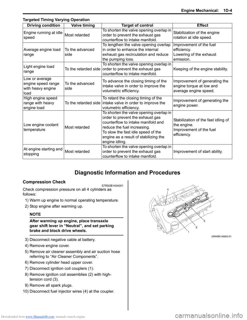
Targeted Timing Varying Operation
Diagnostic Information and Procedures
Compression CheckS7RS0B1404001
Check compression pressure on all 4 cylinders as
follows:
1) Warm up engine to normal operating temperature.
2) Stop engine after warming up.
NOTE
After warming up engine, place transaxle
gear shift lever in “Neutral”, and set parking
brake and block drive wheels.
3) Disconnect negative cable at battery.
4) Remove engine cover.
5) Remove air cleaner assembly and air suction hose referring to “Air Cleaner Components”.
6) Remove cylinder head upper cover.
7) Disconnect ignition coil couplers (1).
8) Remove ignition coil assemblies (2) with high- tension cord (3).
9) Remove all spark plugs.
10) Disconnect fuel injector wires (4) at the coupler. Driving condition Valve timing Target of control Effect
Engine running at idle
speed Most retardedTo shorten the valve opening overlap in
order to prevent the exhaust gas
counterflow to in
take manifold. Stabilization of the engine
rotation at idle speed.
Average engine load
range To the advanced
sideTo lengthen the valve opening overlap
in order to enhance the internal
exhaust gas recirculation and reduce
the pumping loss. Improvement of the fuel
efficiency.
Lowering of the exhaust
emission.
Light engine load
range To the retarded sideTo shorten the valve opening overlap in
order to prevent the exhaust gas
counterflow to in
take manifold. Keeping of the engine stability.
Low or average
engine speed range
with heavy engine
load To the advanced
side
To advance the closing timing of the
intake valve in order to improve the
volumetric efficiency. Improvement of generating the
engine torque at low and
average engine speed.
High engine speed
range with heavy
engine load To the retarded sideTo retard the closing timing of the
intake valve in order to improve the
volumetric efficiency. Improvement of generating the
engine power.
Low engine coolant
temperature Most retardedTo shorten the valve opening overlap in
order to prevent the exhaust gas
counterflow to intake manifold and
reduce the fuel increasing.
To slow the fast idle speed of the
engine as a result of stabilizing the
engine idling. Stabilization of the fast idling of
the engine.
Improvement of the fuel
efficiency.
At engine starting and
stopping Most retardedTo shorten the valve opening overlap in
order to prevent the exhaust gas
counterflow to in
take manifold. Improvement of start ability.I2RH0B140003-01