2008 SUZUKI SWIFT handle
[x] Cancel search: handlePage 872 of 1496
Downloaded from www.Manualslib.com manuals search engine 6B-1 Steering Wheel and Column:
Steeri ng
Steering Wheel and Column
Precautions
Service Precautions of Steering Wheel and
Column
S7RS0B6200001
For service precautions, refer to “Precautions on Service
and Diagnosis of Air Bag System in Section 8B”.
Service and Diagnosis
For diagnosis and servicing, refer to “Precautions on
Service and Diagnosis of Air Bag System in Section 8B”.
Disabling Air Bag System
For disabling air bag system, refer to “Disabling Air Bag
System in Section 8B”. Enabling Air Bag System
For enabling air bag system, refer to “Enabling Air Bag
System in Section 8B”.
Handling and Storage
For handling and storage, refer to “Precautions on
Handling and Storage of Air Bag System Components in
Section 8B”.
Disposal
For disposal, refer to “Prec
autions on Disposal of Air
Bag and Seat Belt Pretensioner in Section 8B”.
General Description
Steering Wheel and Column ConstructionS7RS0B6201001
This double tube type steering column has the following three important features in addition to the steering function:
• The column is energy absorbing, desig ned to compress in a front-end collision.
• The ignition switch and lock are mounted conveniently on this column.
• With the column mounted lock, the ignition and steering op erations can be locked to inhibit theft of the vehicle.
To insure the energy absorbing action, it is important th at only the specified screws, bolts and nuts be used as
designated, and that they are tightened to the specified torque. When the column assembly is removed from the
vehicle, special care must be taken in handling it. Use of a steering wheel puller or a sharp blow on the end of the
steering shaft, leaning on the assembly, or dropping the a ssembly could shear the plastic shear pins which maintain
column length and position.
The driver air bag (inflator) module is one of the supplemental restraint (air bag) system components and is mounted
to the center of the steering wheel. During certain frontal crashes, the air bag system supplements the restraint of the
driver’s and passenger’s seat belts by deploying the air b ags. The air bag (inflator) module should be handled with
care to prevent accidental deployment. When servicing, be sure to observe “Precautions on Service and Diagnosis of
Air Bag System in Section 8B”.
Page 964 of 1496
Downloaded from www.Manualslib.com manuals search engine 7B-16 Air Conditioning System: Manual Type
Repair Instructions
Operation Procedure for Refrigerant ChargeS7RS0B7216001
WARNING!
• Your eyes should not be exposed to refrigerant (liquid).Any liquid HFC-134a (R-134a) escaping by accident shows a temperature as low as approximately –
6 °C (21.2 ° F) below freezing point. Should liquid HFC-134a (R-134a) is exposed to your eyes, it may
cause a serious injury. To protect your eyes from such accident, it is necessary to always wear
goggles. Should it occur that HFC-134a (R-134a) is exposed to your eyes, consult a doctor
immediately.
– Do not use your hand to rub the affected eye(s). Instead, use fresh cold water to splash it over the affected area to gradually raise temperature of such area above freezing point.
– Obtain proper treatment as soon as possible from a doctor or eye specialist.
• Should the liquid refrigerant HFC-134a (R-134a) is exposed to your skin, the affected area should be treated in the same manner as when skin is frostbitten or frozen.
• Do not handle refrigerant near any place where welding or steam cleaning is performed.
• Refrigerant should be kept in a cold and dark pl ace. It should never be stored in any place where
temperature is high, e.g. where exposed to direct su n light, close to fire or inside vehicle (including
trunk room).
• Avoid breathing fume produced when HFC-134a (R-134a) is burned. Such fume may be hazardous to your health.
Recovery
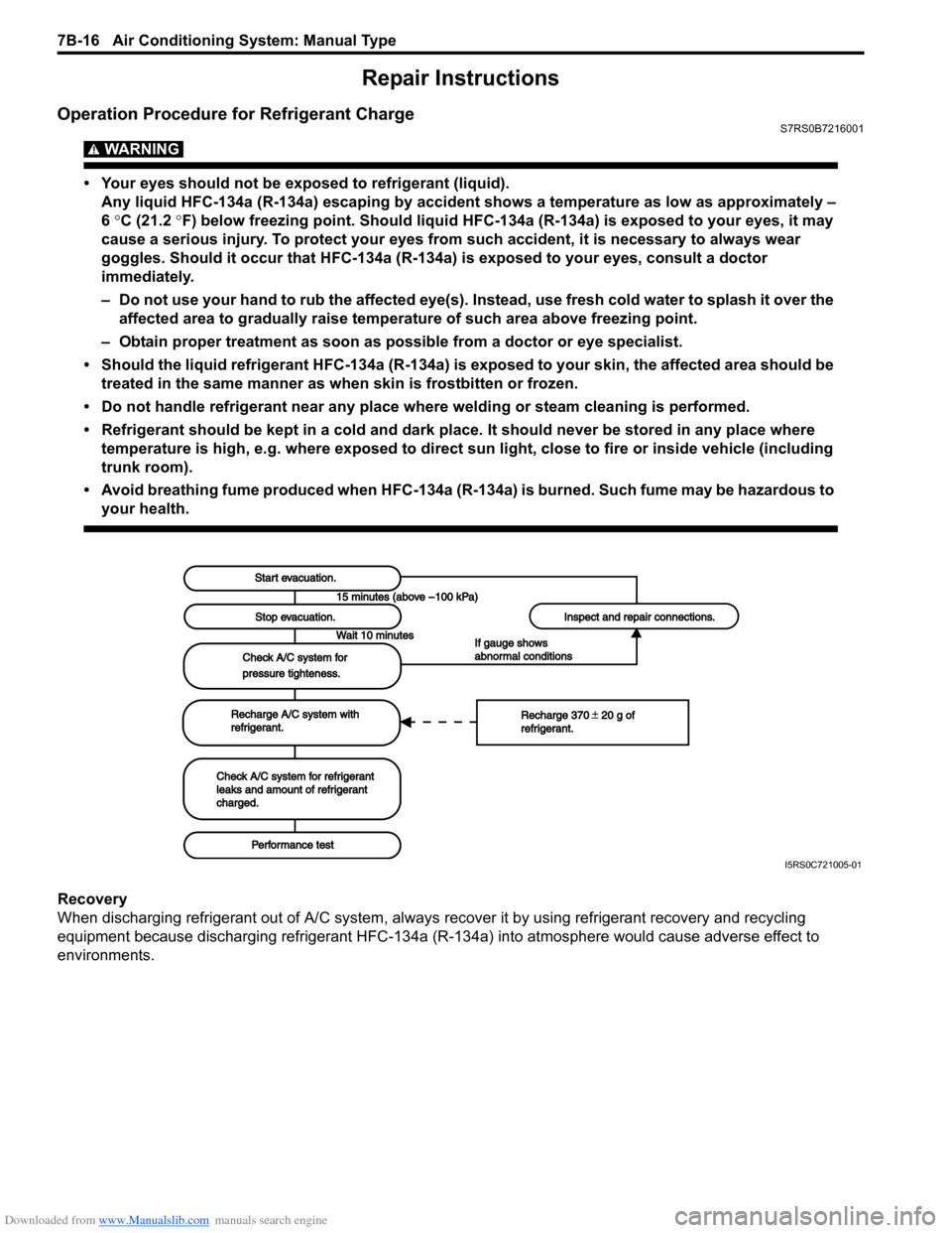
When discharging refrigerant out of A/C system, always recover it by using refrigerant recovery and recycling
equipment because discharging refrigerant HFC-134a (R-1 34a) into atmosphere would cause adverse effect to
environments.
Start evacuation.Start evacuation.
Stop evacuation.Stop evacuation.
Wait 10 minutesWait 10 minutes
Check A/C system forCheck A/C system for
pressure tighteness.pressure tighteness.
Recharge A/C system withRecharge A/C system withrefrigerant.refrigerant.
Check A/C system for refrigerantCheck A/C system for refrigerantleaks and amount of refrigerantleaks and amount of refrigerantcharged.charged.
Performance testPerformance test
Inspect and repair connections.Inspect and repair connections.
If gauge showsIf gauge showsabnormal conditionsabnormal conditions
Recharge 370 20 g ofRecharge 370 20 g ofrefrigerant.refrigerant.
I5RS0C721005-01
Page 968 of 1496
Downloaded from www.Manualslib.com manuals search engine 7B-20 Air Conditioning System: Manual Type
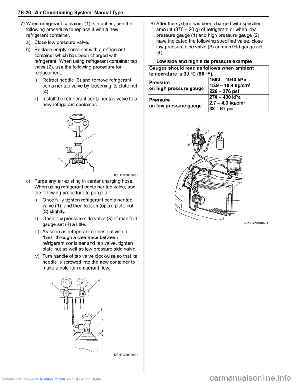
7) When refrigerant container (1) is emptied, use the following procedure to replace it with a new
refrigerant container.
a) Close low pressure valve.
b) Replace empty container with a refrigerant container which has been charged with
refrigerant. When using refrigerant container tap
valve (2), use the following procedure for
replacement.
i) Retract needle (3) and remove refrigerant container tap valve by loosening its plate nut
(4).
ii) Install the refrigerant container tap valve to a new refrigerant container.
c) Purge any air existing in center charging hose. When using refrigerant container tap valve, use
the following procedure to purge air.
i) Once fully tighten refrigerant container tap valve (1), and then loosen (open) plate nut
(2) slightly.
ii) Open low pressure side valve (3) of manifold
gauge set (4) a little.
iii) As soon as refrigerant comes out with a “hiss” through a clearance between
refrigerant container and tap valve, tighten
plate nut as well as low pressure side valve.
iv) Turn handle of tap valve clockwise so that its needle is screwed into the new container to
make a hole for refrigerant flow. 8) After the system has been charged with specified
amount (370 ± 20 g) of refrigerant or when low
pressure gauge (1) and high pressure gauge (2)
have indicated the following specified value, close
low pressure side valve (3) on manifold gauge set
(4).
Low side and high side pressure example
I2RH01720018-01
I2RH01720019-01
Gauges should read as follows when ambient
temperature is 30 °C (86 °F).
Pressure
on high pressure gauge 1590 – 1940 kPa
15.9 – 19.4 kg/cm
2
226 – 276 psi
Pressure
on low pressure gauge 270 – 430 kPa
2.7 – 4.3 kg/cm
2
38 – 61 psi
1
3 42
I4RS0A720016-01
Page 1351 of 1496
Downloaded from www.Manualslib.com manuals search engine Security and Locks: 9F-5
Keyless Entry System Operation InspectionS7RS0B9604004
NOTE
When performing the this inspection, make
sure to have any of the door once opened/
closed after the ignition key has been
removed from the ignition key cylinder.
1) Confirm that power door lock system operates normally, refer to “Power Door Lock System
Operation Inspection”.
2) All doors are closed and unlocked.
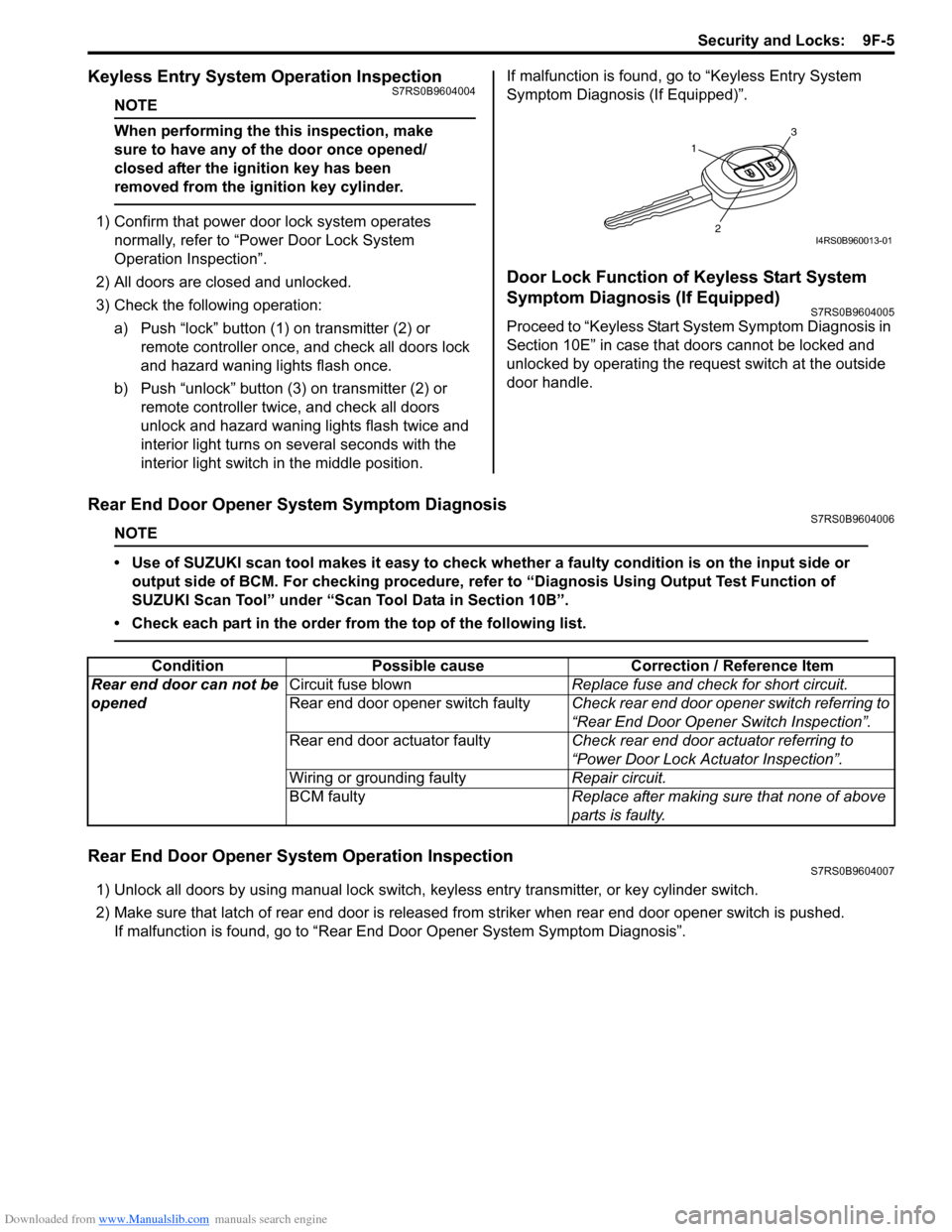
3) Check the following operation: a) Push “lock” button (1 ) on transmitter (2) or
remote controller once, and check all doors lock
and hazard waning lights flash once.
b) Push “unlock” button (3) on transmitter (2) or remote controller twice, and check all doors
unlock and hazard waning lights flash twice and
interior light turns on several seconds with the
interior light switch in the middle position. If malfunction is found, go to “Keyless Entry System
Symptom Diagnosis (If Equipped)”.
Door Lock Function of Keyless Start System
Symptom Diagnosis (If Equipped)
S7RS0B9604005
Proceed to “Keyless Start System Symptom Diagnosis in
Section 10E” in case that doors cannot be locked and
unlocked by operating the request switch at the outside
door handle.
Rear End Door Opener System Symptom DiagnosisS7RS0B9604006
NOTE
• Use of SUZUKI scan tool makes it easy to check wh
ether a faulty condition is on the input side or
output side of BCM. For checking procedure, re fer to “Diagnosis Using Output Test Function of
SUZUKI Scan Tool” under “Scan Tool Data in Section 10B”.
• Check each part in the order from the top of the following list.
Rear End Door Opener System Operation InspectionS7RS0B9604007
1) Unlock all doors by using manu al lock switch, keyless entry transmitter, or key cylinder switch.
2) Make sure that latch of rear end door is released from striker when rear end door opener switch is pushed. If malfunction is found, go to “Rear End Door Opener System Symptom Diagnosis”.
1
3
2I4RS0B960013-01
ConditionPossible cause Correction / Reference Item
Rear end door can not be
opened Circuit fuse blown
Replace fuse and check for short circuit.
Rear end door opener switch faulty Check rear end door opener switch referring to
“Rear End Door Opener Switch Inspection”.
Rear end door actuator faulty Check rear end door actuator referring to
“Power Door Lock Actuator Inspection”.
Wiring or grounding faulty Repair circuit.
BCM faulty Replace after making sure that none of above
parts is faulty.
Page 1352 of 1496
Downloaded from www.Manualslib.com manuals search engine 9F-6 Security and Locks:
Repair Instructions
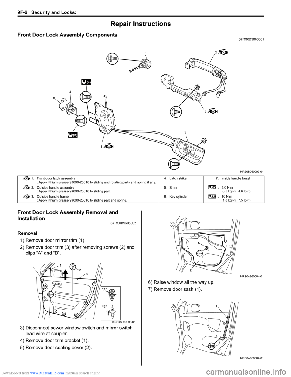
Front Door Lock Assembly ComponentsS7RS0B9606001
Front Door Lock Assembly Removal and
Installation
S7RS0B9606002
Removal1) Remove door mirror trim (1).
2) Remove door trim (3) after removing screws (2) and clips “A” and “B”.
3) Disconnect power window s witch and mirror switch
lead wire at coupler.
4) Remove door trim bracket (1).
5) Remove door sealing cover (2). 6) Raise window all the way up.
7) Remove door sash (1).
(a)
(b)
6
3
7
1
4
5
2
I4RS0B960003-01
1. Front door latch assembly : Apply lithium grease 99000-25010 to sliding and rotating parts and spring if any. 4. Latch striker 7. Inside handle bezel
2. Outside handle assembly : Apply lithium grease 99000-25010 to sliding part. 5. Shim : 5.0 N
⋅m
(0.5 kgf-m, 4.0 lb-ft)
3. Outside handle frame : Apply lithium grease 99000-25010 to sliding part and spring. 6. Key cylinder : 10 N⋅m
(1.0 kgf-m, 7.5 lb-ft)
“B”
“A”
“B”
“A”
“B”“A”
“A”
“A”“A”“A”
12
2 3
I4RS0A960003-01
1
2
I4RS0A960004-01
1
I4RS0A960007-01
Page 1353 of 1496
Downloaded from www.Manualslib.com manuals search engine Security and Locks: 9F-7
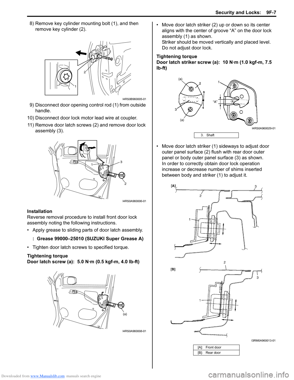
8) Remove key cylinder mounting bolt (1), and then remove key cylinder (2).
9) Disconnect door opening control rod (1) from outside handle.
10) Disconnect door lock motor lead wire at coupler. 11) Remove door latch screws (2) and remove door lock assembly (3).
Installation
Reverse removal procedure to install front door lock
assembly noting the following instructions.
• Apply grease to sliding parts of door latch assembly.
: Grease 99000–25010 (SUZUKI Super Grease A)
• Tighten door latch screws to specified torque.
Tightening torque
Door latch screw (a): 5.0 N·m (0.5 kgf-m, 4.0 lb-ft) • Move door latch striker (2) up or down so its center
aligns with the center of groove “A” on the door lock
assembly (1) as shown.
Striker should be moved vertically and placed level.
Do not adjust door lock.
Tightening torque
Door latch striker screw (a): 10 N·m (1.0 kgf-m, 7.5
lb-ft)
• Move door latch striker (1) sideways to adjust door outer panel surface (2) flush with rear door outer
panel or body outer panel surface (3) as shown.
In order to correctly obtain door lock operation
increase or decrease number of shims inserted
between body and striker (1) to adjust it.
1 2
I4RS0B960005-01
1
2
3
I4RS0A960006-01
(a)
I4RS0A960008-01
3. Shaft
[A]: Front door
[B]: Rear door
I4RS0A960029-01
I3RM0A960013-01
Page 1356 of 1496
Downloaded from www.Manualslib.com manuals search engine 9F-10 Security and Locks:
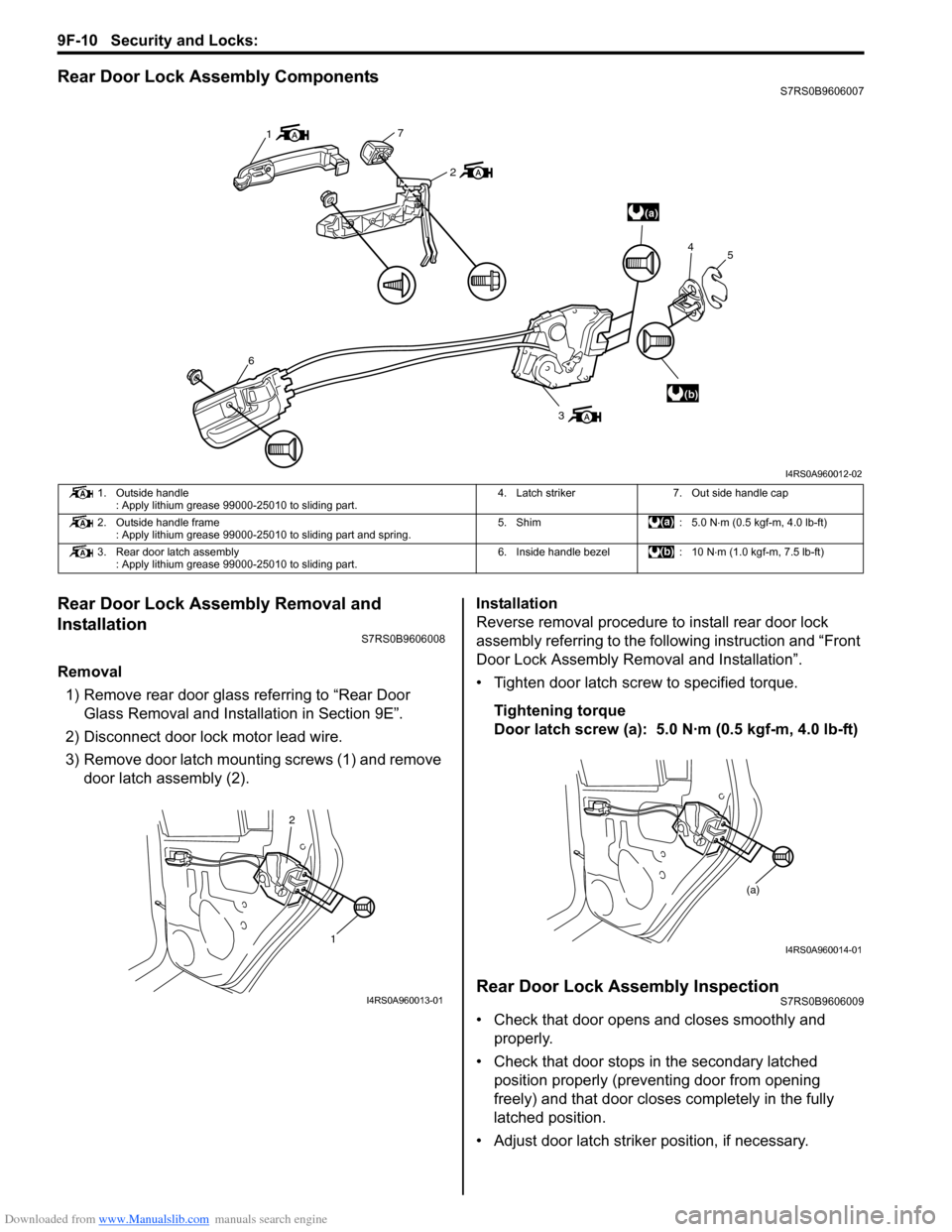
Rear Door Lock Assembly ComponentsS7RS0B9606007
Rear Door Lock Assembly Removal and
Installation
S7RS0B9606008
Removal1) Remove rear door glass referring to “Rear Door Glass Removal and Installation in Section 9E”.
2) Disconnect door lock motor lead wire.
3) Remove door latch mounting screws (1) and remove door latch assembly (2). Installation
Reverse removal procedure to install rear door lock
assembly referring to the following instruction and “Front
Door Lock Assembly Re
moval and Installation”.
• Tighten door latch screw to specified torque.
Tightening torque
Door latch screw (a): 5.0 N·m (0.5 kgf-m, 4.0 lb-ft)
Rear Door Lock Assembly InspectionS7RS0B9606009
• Check that door opens and closes smoothly and properly.
• Check that door stops in the secondary latched position properly (preventing door from opening
freely) and that door closes completely in the fully
latched position.
• Adjust door latch strike r position, if necessary.
(a)
(b)
1
7
2
6
3 4
5
I4RS0A960012-02
1. Outside handle
: Apply lithium grease 99000-25010 to sliding part. 4. Latch striker 7. Out side handle cap
2. Outside handle frame : Apply lithium grease 99000-25010 to sliding part and spring. 5. Shim : 5.0 N
⋅m (0.5 kgf-m, 4.0 lb-ft)
3. Rear door latch assembly : Apply lithium grease 99000-25010 to sliding part. 6. Inside handle bezel : 10 N
⋅m (1.0 kgf-m, 7.5 lb-ft)
1
2
I4RS0A960013-01
(a)
I4RS0A960014-01
Page 1357 of 1496
Downloaded from www.Manualslib.com manuals search engine Security and Locks: 9F-11
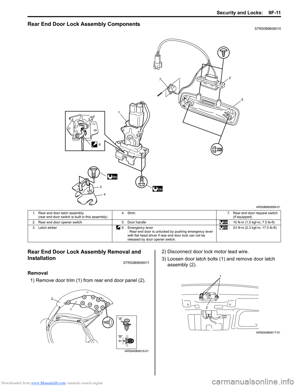
Rear End Door Lock Assembly ComponentsS7RS0B9606010
Rear End Door Lock Assembly Removal and
Installation
S7RS0B9606011
Removal1) Remove door trim (1) from rear end door panel (2). 2) Disconnect door lock motor lead wire.
3) Loosen door latch bolts (1) and remove door latch
assembly (2).
1
7
3 4 5
2
(a)
(b)
6
I4RS0B960009-01
1. Rear end door latch assembly
(rear end door switch is built in this assembly) 4. Shim 7. Rear end door request switch
(if equipped)
2. Rear end door opener switch 5. Door handle : 10 N⋅ m (1.0 kgf-m, 7.5 lb-ft)
3. Latch striker 6. Emergency lever : Rear end door is unlocked by pushing emergency lever
with flat head driver if rear end door lock can not be
released by door opener switch. :23 N
⋅m (2.3 kgf-m, 17.0 lb-ft)
“A”
“B”
“B”
“A”“B”“A”“A”“A”
“A”“A”“A”
“A”
2
1
I4RS0A960016-01
1
2
I4RS0A960017-01