2008 SUZUKI SWIFT checking engine
[x] Cancel search: checking enginePage 272 of 1496
Downloaded from www.Manualslib.com manuals search engine 1B-5 Aux. Emission Control Devices:
PCV Valve InspectionS7RS0B1206010
NOTE
Be sure to check that there is no obstruction
in PCV valve or its hoses before checking
IAC duty, for obstructed PCV valve or hose
hampers its accurate adjustment.
1) Detach air cleaner assembly.
2) Disconnect PCV valve from cylinder head cover and install plug to head cover hole.
3) Install air cleaner assembly temporarily.
4) Run engine at idle.
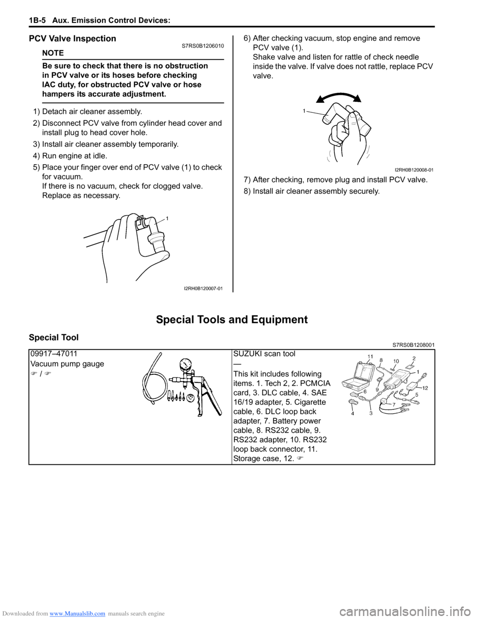
5) Place your finger over end of PCV valve (1) to check for vacuum.
If there is no vacuum, ch eck for clogged valve.
Replace as necessary. 6) After checking vacuum, stop engine and remove
PCV valve (1).
Shake valve and listen for rattle of check needle
inside the valve. If valve does not rattle, replace PCV
valve.
7) After checking, remove plug and install PCV valve.
8) Install air cleaner assembly securely.
Special Tools and Equipment
Special ToolS7RS0B1208001
I2RH0B120007-01
I2RH0B120008-01
09917–47011 SUZUKI scan tool
Vacuum pump gauge —
�) / �) This kit includes following
items. 1. Tech 2, 2. PCMCIA
card, 3. DLC cable, 4. SAE
16/19 adapter, 5. Cigarette
cable, 6. DLC loop back
adapter, 7. Battery power
cable, 8. RS232 cable, 9.
RS232 adapter, 10. RS232
loop back connector, 11.
Storage case, 12. �)
Page 290 of 1496

Downloaded from www.Manualslib.com manuals search engine 1D-5 Engine Mechanical:
11) Connect negative cable at battery.
12) Install special tools (Compression gauge) into spark plug hole.
Special tool
(A): 09915–64512
(B): 09915–64530
(C): 09915–67010
13) Disengage clutch (1) (to lighten starting load on engine) for M/T vehicle, and depress accelerator
pedal (2) all the way to make throttle fully open.
14) Crank engine with fully charged battery, and read the highest pressure on compression gauge.
NOTE
• For measuring compression pressure, crank engine at least 250 r/min. by using
fully charged battery.
• If measured compression pressure is lower than limit value, check installation
condition of special tool. If it is properly
installed, possibility is compression
pressure leakage from where piston ring
and valve contact.
Compression pressure
Standard: 1400 kPa (14.0 kg/cm2, 199.0 psi)
Limit: 1100 kPa (11.0 kg/cm2, 156.0 psi)
Max. difference between any two cylinders: 100
kPa (1.0 kg/cm
2, 14.2 psi) 15) Carry out Steps 12) through 14) on each cylinder to
obtain 4 readings.
16) Disconnect negative cable at battery.
17) After checking, install spark plugs and ignition coil assemblies (2) with high-tension cord (3).
18) Connect ignition coil couplers (1).
19) Connect fuel injector wires (4) at the coupler.
20) Install cylinder head upper cover.
21) Install air cleaner assembly and air suction hose referring to “Air Cleaner Components”.
22) Install engine cover.
23) Connect negative cable at battery.
Engine Vacuum CheckS7RS0B1404002
The engine vacuum that develops in the intake line is a
good indicator of the condition of the engine. The
vacuum checking procedure is as follows:
1) Warm up engine to normal operating temperature.
NOTE
After warming up engine, be sure to place
transaxle gear shift lever in “Neutral”, and set
parking brake and block drive wheels.
2) Stop engine and turn off the all electric switches.
3) Remove engine cover.
4) Remove air cleaner assembly and air suction hose referring to “Air Cleaner Components”.
5) Remove PCV hose (1) from PCV valve (2).
(A)
(C)
(B)
I3RH0B140009-01
I2RH0B140005-01
I2RH0B140003-01
2
1
I6RS0B141001-01
Page 293 of 1496
Downloaded from www.Manualslib.com manuals search engine Engine Mechanical: 1D-8
For example of intake side:
When thickness of removed shim is 2.40 mm (0.094
in.), and measured valve clearance is 0.45 mm
(0.018 in.).
A = 2.40 mm (0.094 in.) + 0.45 mm (0.018 in.) – 0.20
mm (0.008 in.) = 2.65 mm (0.104 in.)
Calculated thickness of new shim = 2.65 mm (0.104
in.)
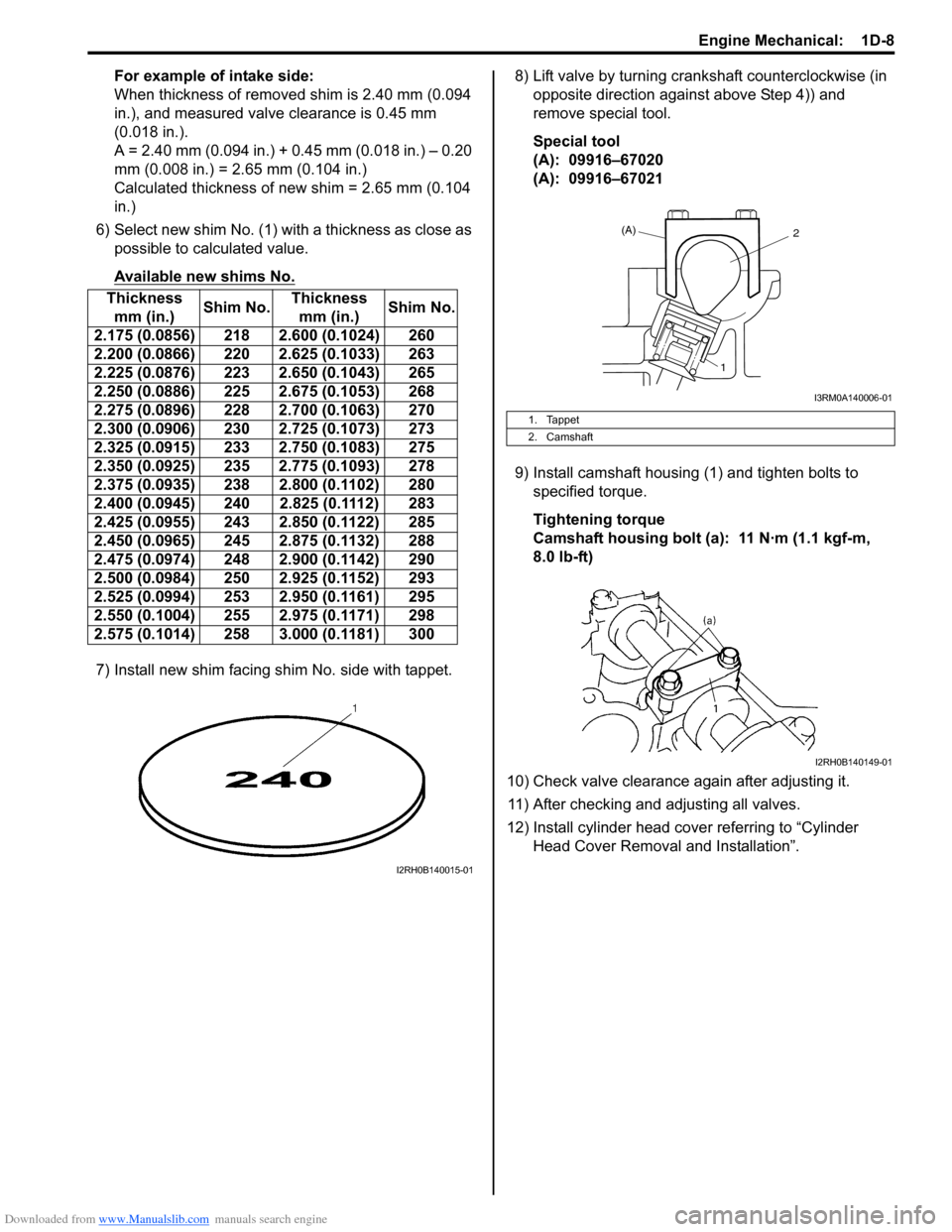
6) Select new shim No. (1) with a thickness as close as possible to calculated value.
Available new shims No.
7) Install new shim facing shim No. side with tappet. 8) Lift valve by turning crankshaft counterclockwise (in
opposite direction against above Step 4)) and
remove special tool.
Special tool
(A): 09916–67020
(A): 09916–67021
9) Install camshaft housing (1) and tighten bolts to specified torque.
Tightening torque
Camshaft housing bolt (a ): 11 N·m (1.1 kgf-m,
8.0 lb-ft)
10) Check valve clearance again after adjusting it. 11) After checking and adjusting all valves.
12) Install cylinder head cover referring to “Cylinder Head Cover Removal and Installation”.
Thickness
mm (in.) Shim No.Thickness
mm (in.) Shim No.
2.175 (0.0856) 218 2.600 (0.1024) 260
2.200 (0.0866) 220 2.625 (0.1033) 263
2.225 (0.0876) 223 2.650 (0.1043) 265
2.250 (0.0886) 225 2.675 (0.1053) 268
2.275 (0.0896) 228 2.700 (0.1063) 270
2.300 (0.0906) 230 2.725 (0.1073) 273
2.325 (0.0915) 233 2.750 (0.1083) 275
2.350 (0.0925) 235 2.775 (0.1093) 278
2.375 (0.0935) 238 2.800 (0.1102) 280
2.400 (0.0945) 240 2.825 (0.1112) 283
2.425 (0.0955) 243 2.850 (0.1122) 285
2.450 (0.0965) 245 2.875 (0.1132) 288
2.475 (0.0974) 248 2.900 (0.1142) 290
2.500 (0.0984) 250 2.925 (0.1152) 293
2.525 (0.0994) 253 2.950 (0.1161) 295
2.550 (0.1004) 255 2.975 (0.1171) 298
2.575 (0.1014) 258 3.000 (0.1181) 300
I2RH0B140015-01
1. Tappet
2. Camshaft
(A)2
1
I3RM0A140006-01
I2RH0B140149-01
Page 317 of 1496
Downloaded from www.Manualslib.com manuals search engine Engine Mechanical: 1D-32
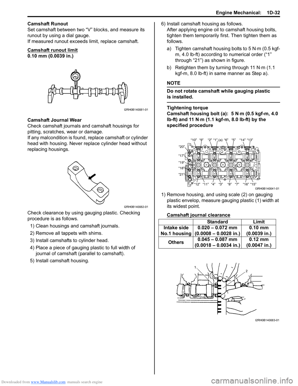
Camshaft Runout
Set camshaft between two “V” blocks, and measure its
runout by using a dial gauge.
If measured runout exceeds limit, replace camshaft.
Camshaft runout limit
0.10 mm (0.0039 in.)
Camshaft Journal Wear
Check camshaft journals and camshaft housings for
pitting, scratches, wear or damage.
If any malcondition is found, replace camshaft or cylinder
head with housing. Never re place cylinder head without
replacing housings.
Check clearance by using ga uging plastic. Checking
procedure is as follows.
1) Clean housings and camshaft journals.
2) Remove all tappets with shims.
3) Install camshafts to cylinder head.
4) Place a piece of gauging plastic to full width of
journal of camshaft (parallel to camshaft).
5) Install camshaft housing. 6) Install camshaft housing as follows.
After applying engine oil to camshaft housing bolts,
tighten them temporarily first. Then tighten them as
follows.
a) Tighten camshaft housing bolts to 5 N ⋅m (0.5 kgf-
m, 4.0 lb-ft) according to numerical order (“1”
through “21”) as shown in figure.
b) Retighten them by turning through 11 N ⋅m (1.1
kgf-m, 8.0 lb-ft) in same manner as Step a).
NOTE
Do not rotate camshaft while gauging plastic
is installed.
Tightening torque
Camshaft housing bolt (a): 5 N ⋅m (0.5 kgf-m, 4.0
lb-ft) and 11 N ⋅m (1.1 kgf-m, 8.0 lb-ft) by the
specified procedure
1) Remove housing, and using scale (2) on gauging plastic envelop, measure gauging plastic (1) width at
its widest point.
Camshaft journal clearanceI2RH0B140081-01
I2RH0B140082-01
Standard Limit
Intake side
No.1 housing 0.020 – 0.072 mm
(0.0008 – 0.0028 in.) 0.10 mm
(0.0039 in.)
Others 0.045 – 0.087 mm
(0.0018 – 0.0034 in.) 0.12 mm
(0.0047 in.)
“10”“9” “2” “1”,(a) “6” “5” “14” “13”
“20”
“17” “19”
“18”
“21”
“12”“11”
“4” “3” “8” “7” “16” “15”
I3RH0B140041-01
I2RH0B140083-01
Page 330 of 1496
Downloaded from www.Manualslib.com manuals search engine 1D-45 Engine Mechanical:
Pistons, Piston Rings, Connecting Rods and
Cylinders Removal and Installation
S7RS0B1406030
Removal1) Remove engine assembly from vehicle referring to “Engine Assembly Removal and Installation”.
2) Remove cylinder head referring to “Valves and Cylinder Head Removal and Installation”.
3) Mark cylinder number on all pistons, connecting rods
and connecting rod caps using silver pencil or quick
drying paint.
4) Remove rod bearing caps.
5) Decarbonize top of cylinder bore before removing piston from cylinder.
6) Push piston and connecting rod assembly out through the top of cylinder bore.
Installation 1) Apply engine oil to pistons, rings, cylinder walls, connecting rod bearings and crank pins.
NOTE
Do not apply oil between connecting rod and
bearing or between bearing cap and bearing.
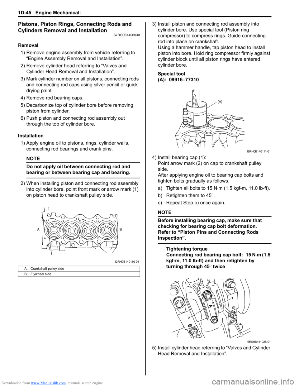
2) When installing piston and connecting rod assembly into cylinder bore, point front mark or arrow mark (1)
on piston head to crankshaft pulley side. 3) Install piston and connecting rod assembly into
cylinder bore. Use special tool (Piston ring
compressor) to compress rings. Guide connecting
rod into place on crankshaft.
Using a hammer handle, tap piston head to install
piston into bore. Hold ring compressor firmly against
cylinder block until all piston rings have entered
cylinder bore.
Special tool
(A): 09916–77310
4) Install bearing cap (1): Point arrow mark (2) on cap to crankshaft pulley
side.
After applying engine oil to bearing cap bolts and
tighten bolts gradually as follows.
a) Tighten all bolts to 15 N ⋅m (1.5 kgf-m, 11.0 lb-ft).
b) Retighten them to 45 °.
c) Repeat Step b) once again.
NOTE
Before installing bearing cap, make sure that
checking for bearing cap bolt deformation.
Refer to “Piston Pins and Connecting Rods
Inspection”.
Tightening torque
Connecting rod bearing cap bolt: 15 N ⋅m (1.5
kgf-m, 11.0 lb-ft) and then retighten by
turning through 45 ° twice
5) Install cylinder head referring to “Valves and Cylinder Head Removal and Installation”.
A: Crankshaft pulley side
B: Flywheel side
I2RH0B140110-01
I2RH0B140111-01
I6RS0B141025-01
Page 333 of 1496
Downloaded from www.Manualslib.com manuals search engine Engine Mechanical: 1D-48
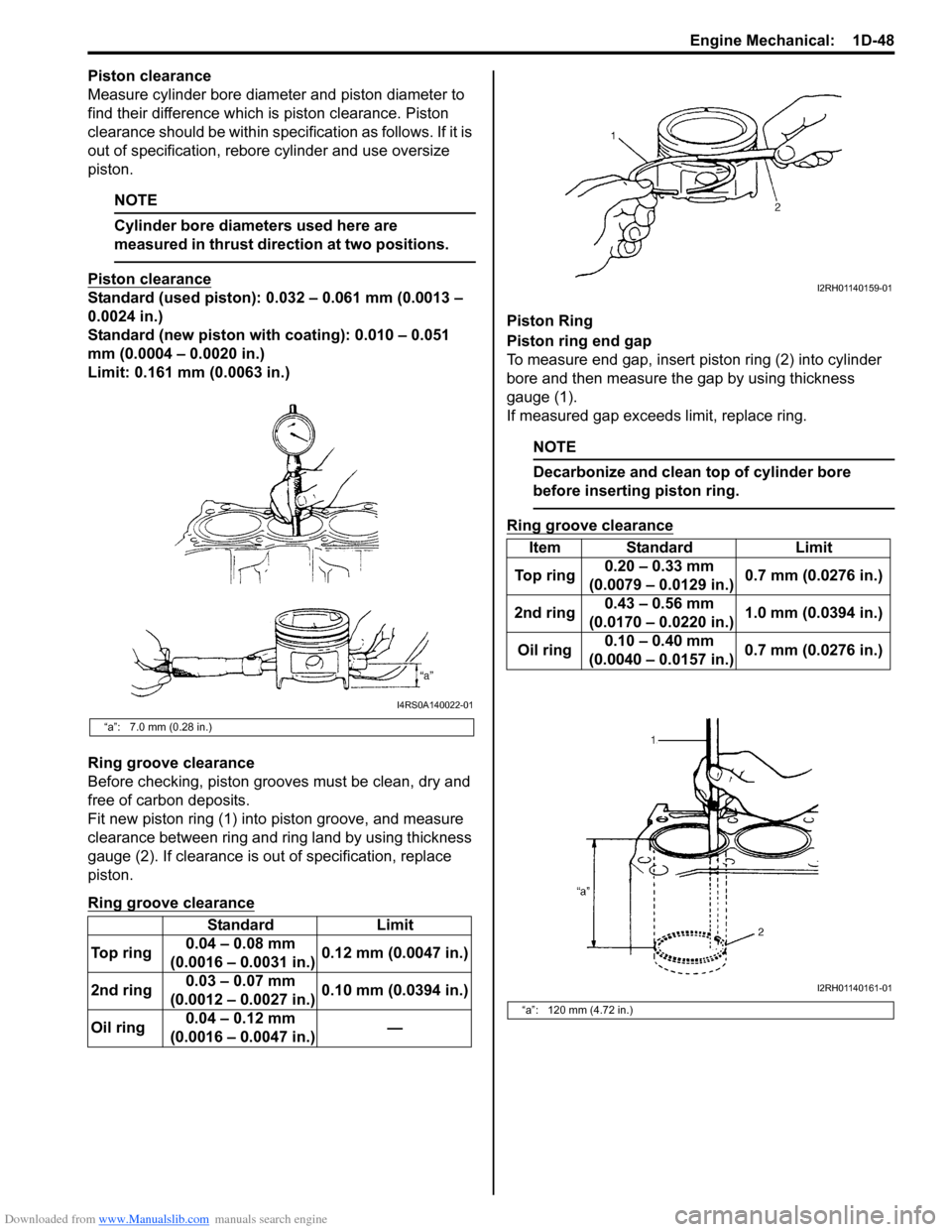
Piston clearance
Measure cylinder bore diameter and piston diameter to
find their difference which is piston clearance. Piston
clearance should be within spec ification as follows. If it is
out of specification, rebore cylinder and use oversize
piston.
NOTE
Cylinder bore diameters used here are
measured in thrust direction at two positions.
Piston clearance
Standard (used piston): 0.032 – 0.061 mm (0.0013 –
0.0024 in.)
Standard (new piston with coating): 0.010 – 0.051
mm (0.0004 – 0.0020 in.)
Limit: 0.161 mm (0.0063 in.)
Ring groove clearance
Before checking, piston grooves must be clean, dry and
free of carbon deposits.
Fit new piston ring (1) into piston groove, and measure
clearance between ring and ring land by using thickness
gauge (2). If clearance is ou t of specification, replace
piston.
Ring groove clearance
Piston Ring
Piston ring end gap
To measure end gap, insert piston ring (2) into cylinder
bore and then measure the gap by using thickness
gauge (1).
If measured gap exceeds limit, replace ring.
NOTE
Decarbonize and clean top of cylinder bore
before inserting piston ring.
Ring groove clearance
“a”: 7.0 mm (0.28 in.)
Standard Limit
Top ring 0.04 – 0.08 mm
(0.0016 – 0.0031 in.) 0.12 mm (0.0047 in.)
2nd ring 0.03 – 0.07 mm
(0.0012 – 0.0027 in.) 0.10 mm (0.0394 in.)
Oil ring 0.04 – 0.12 mm
(0.0016 – 0.0047 in.) —
I4RS0A140022-01
Item Standard
Limit
To p r i n g 0.20 – 0.33 mm
(0.0079 – 0.0129 in.) 0.7 mm (0.0276 in.)
2nd ring 0.43 – 0.56 mm
(0.0170 – 0.0220 in.) 1.0 mm (0.0394 in.)
Oil ring 0.10 – 0.40 mm
(0.0040 – 0.0157 in.) 0.7 mm (0.0276 in.)
“a”: 120 mm (4.72 in.)
I2RH01140159-01
I2RH01140161-01
Page 336 of 1496
Downloaded from www.Manualslib.com manuals search engine 1D-51 Engine Mechanical:
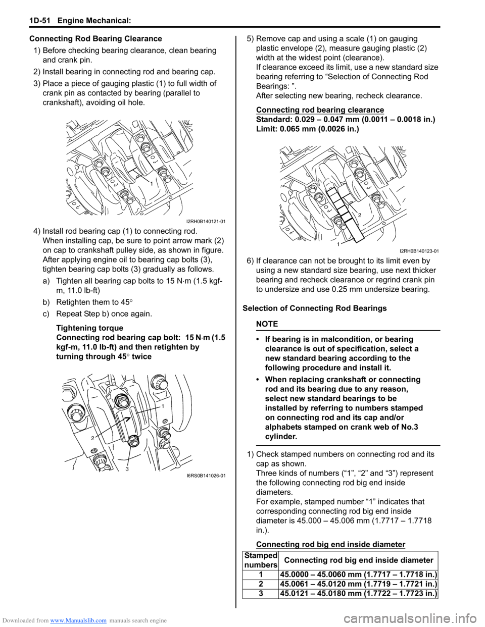
Connecting Rod Bearing Clearance1) Before checking bearing clearance, clean bearing and crank pin.
2) Install bearing in connecting rod and bearing cap.
3) Place a piece of gauging plastic (1) to full width of crank pin as contacted by bearing (parallel to
crankshaft), avoiding oil hole.
4) Install rod bearing cap (1) to connecting rod. When installing cap, be sure to point arrow mark (2)
on cap to crankshaft pulley side, as shown in figure.
After applying engine oil to bearing cap bolts (3),
tighten bearing cap bolts (3) gradually as follows.
a) Tighten all bearing cap bolts to 15 N ⋅m (1.5 kgf-
m, 11.0 lb-ft)
b) Retighten them to 45°
c) Repeat Step b) once again.
Tightening torque
Connecting rod bearing cap bolt: 15 N ⋅m (1.5
kgf-m, 11.0 lb-ft) and then retighten by
turning through 45 ° twice 5) Remove cap and using a scale (1) on gauging
plastic envelope (2), measure gauging plastic (2)
width at the widest point (clearance).
If clearance exceed its limit, use a new standard size
bearing referring to “Selection of Connecting Rod
Bearings: ”.
After selecting new bearing, recheck clearance.
Connecting rod bearing clearance
Standard: 0.029 – 0.047 mm (0.0011 – 0.0018 in.)
Limit: 0.065 mm (0.0026 in.)
6) If clearance can not be brought to its limit even by using a new standard size bearing, use next thicker
bearing and recheck clearance or regrind crank pin
to undersize and use 0.25 mm undersize bearing.
Selection of Connecting Rod Bearings
NOTE
• If bearing is in malcondition, or bearing clearance is out of specification, select a
new standard bearing according to the
following procedure and install it.
• When replacing crankshaft or connecting rod and its bearing due to any reason,
select new standard bearings to be
installed by referring to numbers stamped
on connecting rod and its cap and/or
alphabets stamped on crank web of No.3
cylinder.
1) Check stamped numbers on connecting rod and its cap as shown.
Three kinds of numbers (“1”, “2” and “3”) represent
the following connecting rod big end inside
diameters.
For example, stamped number “1” indicates that
corresponding connecting rod big end inside
diameter is 45.000 – 45.006 mm (1.7717 – 1.7718
in.).
Connecting rod big end inside diameter
I2RH0B140121-01
I6RS0B141026-01
Stamped
numbers Connecting rod big end inside diameter
1 45.0000 – 45.0060 mm (1.7717 – 1.7718 in.)
2 45.0061 – 45.0120 mm (1.7719 – 1.7721 in.)
3 45.0121 – 45.0180 mm (1.7722 – 1.7723 in.)
I2RH0B140123-01
Page 343 of 1496
Downloaded from www.Manualslib.com manuals search engine Engine Mechanical: 1D-58
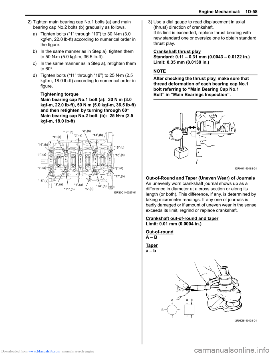
2) Tighten main bearing cap No.1 bolts (a) and main bearing cap No.2 bolts (b ) gradually as follows.
a) Tighten bolts (“1” through “10”) to 30 N ⋅m (3.0
kgf-m, 22.0 lb-ft) according to numerical order in
the figure.
b) In the same manner as in Step a), tighten them to 50 N ⋅m (5.0 kgf-m, 36.5 lb-ft).
c) In the same manner as in Step a), retighten them to 60 °.
d) Tighten bolts (“11” through “18”) to 25 N ⋅m (2.5
kgf-m, 18.0 lb-ft) according to numerical order in
figure.
Tightening torque
Main bearing cap No.1 bolt (a): 30 N ⋅m (3.0
kgf-m, 22.0 lb-ft), 50 N ⋅m (5.0 kgf-m, 36.5 lb-ft)
and then retighten by turning through 60 °
Main bearing cap No.2 bolt (b): 25 N·m (2.5
kgf-m, 18.0 lb-ft) 3) Use a dial gauge to read displacement in axial
(thrust) direction of crankshaft.
If its limit is exceeded, replace thrust bearing with
new standard one or oversize one to obtain standard
thrust play.
Crankshaft thrust play
Standard: 0.11 – 0.31 mm (0.0043 – 0.0122 in.)
Limit: 0.35 mm (0.0138 in.)
NOTE
After checking the thrust play, make sure that
thread deformation of each bearing cap No.1
bolt referring to “Main Bearing Cap No.1
Bolt” in “Main Bear ings Inspection”.
Out-of-Round and Taper (Uneven Wear) of Journals
An unevenly worn crankshaft journal shows up as a
difference in diameter at a cross section or along its
length (or both). This difference, if any, is determined by
taking micrometer readings. If any one of journals is
badly damaged or if amount of uneven wear in the sense
exceeds its limit, regrind or replace crankshaft.
Crankshaft out-of-round and taper
Limit: 0.01 mm (0.0004 in.)
Out-of-round
A – B
Ta p e r
a – b
I6RS0C140027-01
I2RH01140183-01
I2RH0B140138-01