2008 SUZUKI SWIFT air box
[x] Cancel search: air boxPage 563 of 1496

Downloaded from www.Manualslib.com manuals search engine ABS: 4E-24
DTC C1071: ABS Control ModuleS7RS0B4504017
Wiring Diagram
DTC Detecting Condition
This DTC will be set when an internal malfunction is detected in the ABS control module.
DTC Troubleshooting
1
2
WHT/RED
12VM
3
4
E03-1
E03-14
BLK
BLK
E03-13
E03-26
WHT/BLU [A]
E03
15
16
17
18
19
20
21
22
23
24
25 2
3
4
5
6
7
8
9
10
11
12
1
13
14
26
I6RS0C450014-01
[A]: ABS hydraulic unit / control module connector
(viewed from terminal side) 2. Main fuse box 4. ABS hydraulic unit / control module assembly
1. Battery 3. ABS power control module
Step Action YesNo
1 Was “ABS Check” performed? Go to Step 2.Go to “ABS Check”.
2 Clear all DTCs and check DTC.
Is it DTC C1071? Go to Step 3.
Could be a temporary
malfunction of the ABS
control module.
3 1) Check for proper connection of ABS hydraulic unit / control module connector.
2) If OK, disconnect ABS hydr aulic unit / control module
connector and check the following.
• Voltage “E03-1” terminal: 10 – 14 V
• Voltage “E03-14” terminal: 10 – 14 V
• Resistance between “E03-13” and body ground: Continuity
• Resistance between “E03-26” and body ground: Continuity
Are the check result as specified? Replace ABS hydraulic
unit / control module
assembly.
Repair “WHT/RED”,
“WHT/BLU” and/or
“BLK” circuit and
recheck.
Page 597 of 1496
Downloaded from www.Manualslib.com manuals search engine Electronic Stability Program: 4F-23
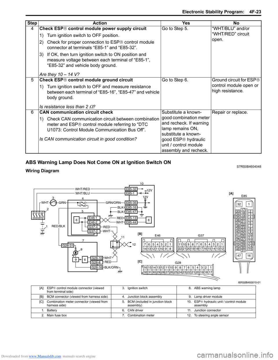
ABS Warning Lamp Does Not Come ON at Ignition Switch ONS7RS0B4604048
Wiring Diagram4
Check ESP ® control module power supply circuit
1) Turn ignition switch to OFF position.
2) Check for proper connection to ESP ® control module
connector at terminals “E85-1” and “E85-32”.
3) If OK, then turn ignition switch to ON position and measure voltage between each terminal of “E85-1”,
“E85-32” and vehicle body ground.
Are they 10 – 14 V? Go to Step 5. “WHT/BLU” and/or
“WHT/RED” circuit
open.
5 Check ESP ® control module ground circuit
1) Turn ignition switch to OFF and measure resistance between each terminal of “E85-16”, “E85-47” and vehicle
body ground.
Is resistance less than 2
Ω? Go to Step 6.
Ground circuit for ESP®
control module open or
high resistance.
6 CAN communication circuit check
1) Check CAN communication circuit between combination
meter and ESP ® control module referring to “DTC
U1073: Control Module Communication Bus Off”.
Is CAN communication circuit in good condition? Substitute a known-
good combination meter
and recheck. If warning
lamp remains ON,
substitute a known-
good ESP
® hydraulic
unit / control module
assembly and recheck. Repair or replace.
Step
Action YesNo
[A]
E85
161
15
2
3
4
5
6
7
8
9
10
11
12
13
14
17
18
19
20
21
22
23
24
25
26
27
28
29
30
31
3233
34
35
36
37
38
39
40
41
42
43
44
45
46
47
WHTGRN
3
E85-13
E85-44REDWHT6 5E46-1E46-2
4 10
6
E85-16
E85-47BLKBLK
8
9
BLK/ORN
REDWHT
REDWHT
G37-4G37-2
G28-10G28-8
G28-16
12V
12VE85-32E85-1
E85-35
WHT/REDWHT/BLU
GRN/ORN
6
2
1
7 1112[B]
G37
E46124
53
67
891011121314124
53
67
891011
1213141516171819202122
[C] G28
12345678910111213141516
17181920212223242526272829303132
G28-31
RED/BLK
I6RS0B460010-01
[A]: ESP ® control module connector (viewed
from terminal side) 3. Ignition switch 8. ABS warning lamp
[B]: BCM connector (viewed from harness side) 4. Junction block assembly 9. Lamp driver module
[C]: Combination meter connector (viewed from harness side) 5. BCM (included in junction block
assembly) 10. ESP
® hydraulic unit / control module
assembly
1. Battery 6. CAN driver11. Junction connector
2. Main fuse box 7. Combination meter12. To steering angle sensor
Page 747 of 1496
Downloaded from www.Manualslib.com manuals search engine Automatic Transmission/Transaxle: 5A-103
Installation
Reverse removal procedure noting the following.
• Connect TCM connectors securely.
• If the vehicle is equipped with air bag system, be sure to enable air bag system after TCM is back in place.
Refer to “Enabling Air Bag System in Section 8B”.
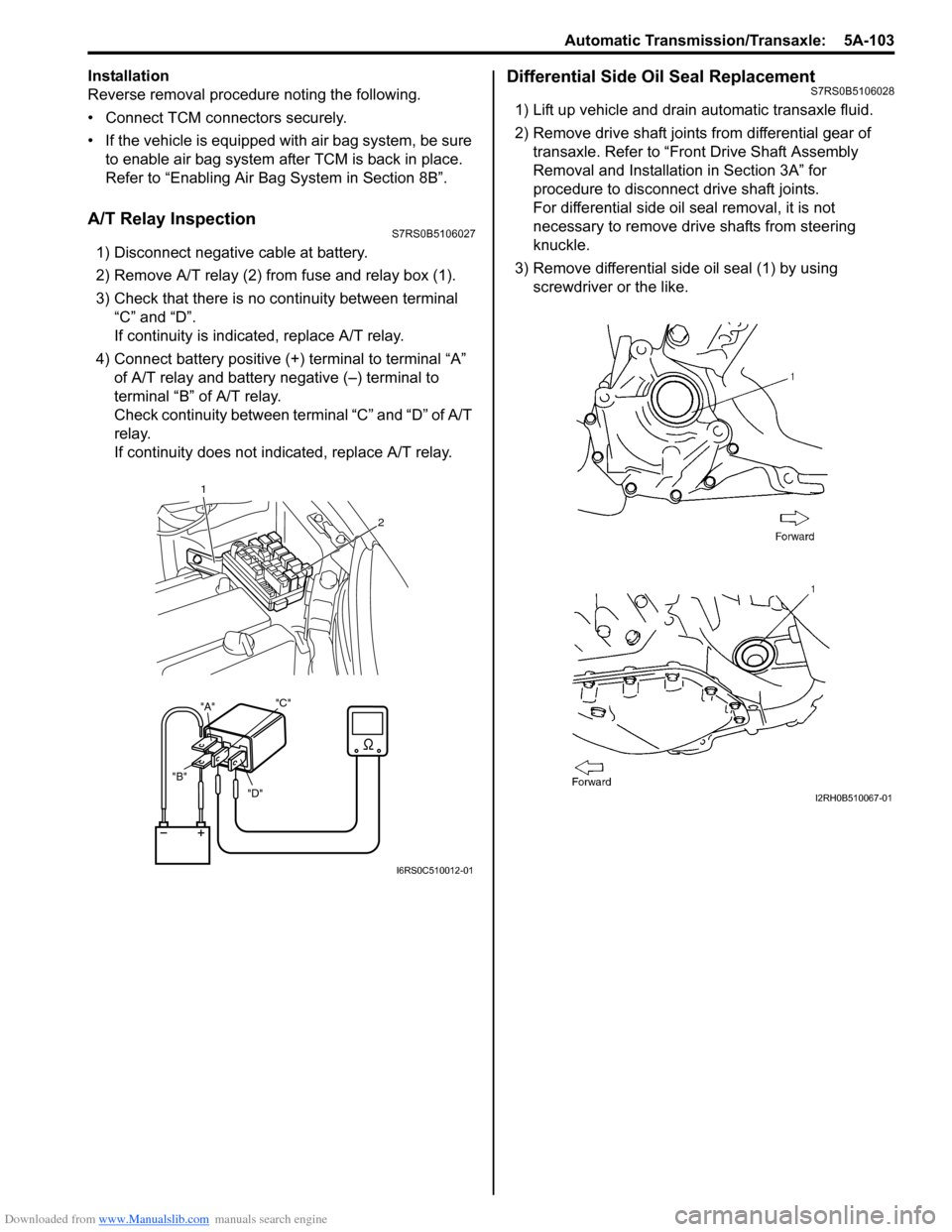
A/T Relay InspectionS7RS0B5106027
1) Disconnect negative cable at battery.
2) Remove A/T relay (2) from fuse and relay box (1).
3) Check that there is no continuity between terminal “C” and “D”.
If continuity is indicated, replace A/T relay.
4) Connect battery positive (+ ) terminal to terminal “A”
of A/T relay and battery negative (–) terminal to
terminal “B” of A/T relay.
Check continuity between terminal “C” and “D” of A/T
relay.
If continuity does not indicated, replace A/T relay.
Differential Side Oil Seal ReplacementS7RS0B5106028
1) Lift up vehicle and drain automatic transaxle fluid.
2) Remove drive shaft joints from differential gear of transaxle. Refer to “Front Drive Shaft Assembly
Removal and Installation in Section 3A” for
procedure to disconnect drive shaft joints.
For differential side oil seal removal, it is not
necessary to remove drive shafts from steering
knuckle.
3) Remove differential side oil seal (1) by using screwdriver or the like.
"D"
"B" "A"
"C"
1
2
I6RS0C510012-01
I2RH0B510067-01
Page 886 of 1496

Downloaded from www.Manualslib.com manuals search engine 6C-4 Power Assisted Steering System:
Schematic and Routing Diagram
EPS System Wiring Circuit DiagramS7RS0B6302001
M
5V
BRNRED/
BLU
BLK
RED
WHT
BLU
GRN
BRN YEL
E52-11
E52-14E52-12
E23-4
E23-26
E23-25 E51-1
E51-2
E52-18
E53-5
E53-7
E52-6
E52-8
E53-2
E52-9
E52-16
E52-19
GRY
PPL/WHT
[A ]
[E ]
12 3
4 5 67
89
11
10
12 13
141516
17 18 19 20
1
2
[B ][C ]
1210 9 8 7654 3 21
16 15 14 13 12 11
26 25 24 2322 21 20 19 18 17
32 31 30 29 28 27
[D]
5V
PPL
E52-4
11
12
13 14
15
10
9
16
12V
5V
5V
12V
REDE52-20E53-6
E53-4
E53-1
7654321
5
REDRED/
BLKWHT
6WHTWHT/BLKWHTBLK
12V
12V
17BLK
GRY
LT GRN
/BLK
E52-1
E52-5
E49-1
GRNGRNWHTBLK
WHY
G28-25G28-31
RED/BLK
18
3
4
4
7 8
4
4
1 2
4
E49-2BLK
I7RS0B630002-01
[A]: Connector “E52” (viewed from harness side) 4. Fuse 12. P/S motor
[B]: Connector “E49” (viewed from harness side ) 5. Left-front wheel speed sensor 13. Shield
[C]: Connector “E51” (viewed from harness side) 6 . Right-front wheel speed sensor 14. Torque sensor
[D]: Connector “G28” (viewed from harness side) 7. Combination meter 15. Torque sensor amplifier
[E]: Connector “E53” (viewed from harness side) 8. “EPS” warning light16. To ECM, BCM, Air bag SDM and ABS control module assembly
1. Main fuse box 9. Date link connector (DLC) 17. ABS/ESP ® control module
2. Ignition switch 10. ECM18. Individual circuit fuse box No.1
3. Junction block assembly 11. P/S control module
Page 895 of 1496
Downloaded from www.Manualslib.com manuals search engine Power Assisted Steering System: 6C-13
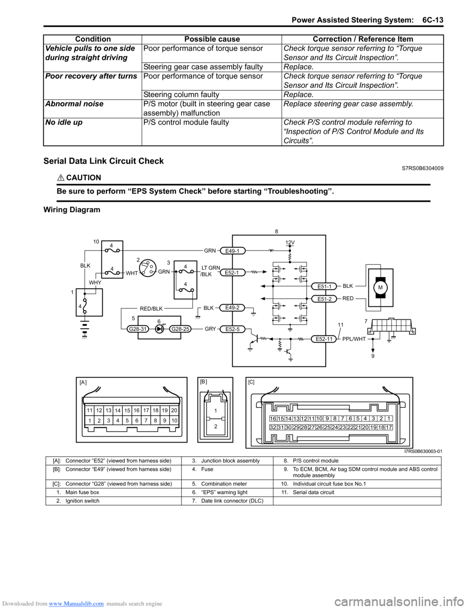
Serial Data Link Circuit CheckS7RS0B6304009
CAUTION!
Be sure to perform “EPS System Check” before starting “Troubleshooting”.
Wiring DiagramVehicle pulls to one side
during straight driving
Poor performance of torque sensor
Check torque sensor referring to “Torque
Sensor and Its Circuit Inspection”.
Steering gear case assembly faulty Replace.
Poor recovery after turns Poor performance of torque sensor Check torque sensor referring to “Torque
Sensor and Its Circuit Inspection”.
Steering column faulty Replace.
Abnormal noise P/S motor (built in steering gear case
assembly) malfunction Replace steering gear case assembly.
No idle up P/S control module faulty Check P/S control module referring to
“Inspection of P/S Control Module and Its
Circuits”.
Condition Possible cause Correction / Reference Item
MBLK
RED
E52-11 E51-1
E51-2PPL/WHT
[A ]
12
3
4 5 67
89
11
10
12 13
141516
17 18 19 2010 9 8 7654 3 21
16 15 14 13 12 11
26 25 24 2322 21 20 19 18 17
32 31 30 29 28 27
[C]
8
79
12V
[B ]
11
12
GRY
LT GRN
/BLK
E52-1
E52-5
E49-1
GRNGRNWHTBLK
WHY
G28-25G28-31
RED/BLK
10
3
4
4
5 6
4
4
1 2
4
E49-2BLK
I7RS0B630003-01
[A]: Connector “E52” (viewed from harness side) 3. Junction block assembly 8. P/S control module
[B]: Connector “E49” (viewed from harness side) 4. Fuse 9. T o ECM, BCM, Air bag SDM control module and ABS control
module assembly
[C]: Connector “G28” (viewed from harness side) 5. Comb ination meter 10. Individual circuit fuse box No.1
1. Main fuse box 6. “EPS” warning light 11. Serial data circuit
2. Ignition switch 7. Date link connector (DLC)
Page 897 of 1496
Downloaded from www.Manualslib.com manuals search engine Power Assisted Steering System: 6C-15
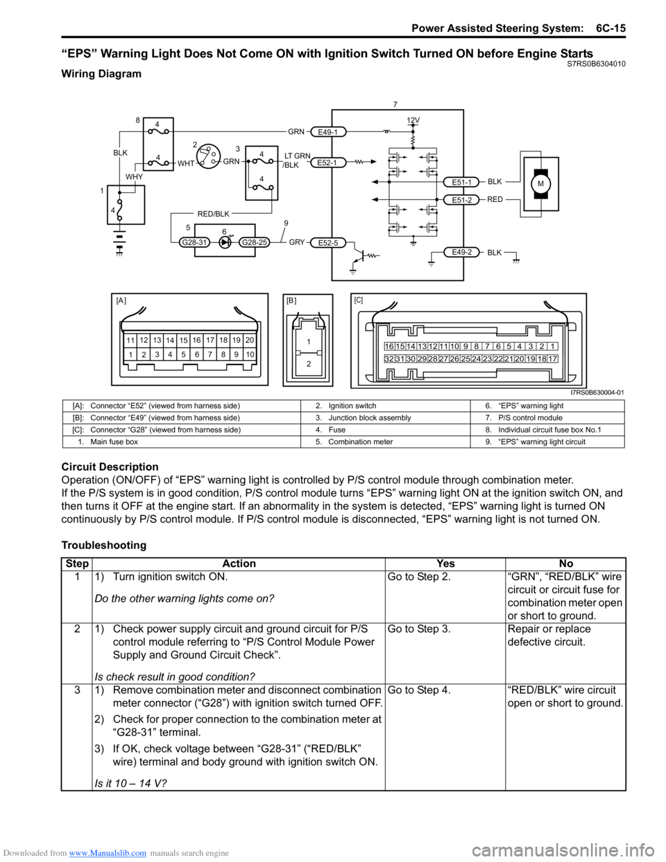
“EPS” Warning Light Does Not Come ON with Ignition Switch Turned ON before Engine StartsS7RS0B6304010
Wiring Diagram
Circuit Description
Operation (ON/OFF) of “EPS” warning light is controlled by P/S control module through combination meter.
If the P/S system is in good condition, P/S control module turns “ EPS” warning light ON at the ignition switch ON, and
then turns it OFF at the engine start. If an abnormality in the system is detected, “EPS” warning light is turned ON
continuously by P/S control module. If P/S control module is disconnected, “EPS” warning light is not turned ON.
Troubleshooting
MBLK
REDE51-1
E51-2
[A ]
12 3
4 5 67
89
11
10
12 13
141516
17 18 19 2010 9 8 7654 3 21
16 15 14 13 12 11
26 25 24 2322 21 20 19 18 17
32 31 30 29 28 27
[C]
7
12V
E49-2BLK
[B ]
1 2
GRY
LT GRN
/BLK
E52-1
E52-5
E49-1
GRNGRNWHTBLK
WHY
G28-25G28-31
RED/BLK
8
3
4
4
5 6
4
4
1 2
4
9
I7RS0B630004-01
[A]: Connector “E52” (viewed from harness side) 2. Ignition switch6. “EPS” warning light
[B]: Connector “E49” (viewed from harness side) 3. Junction block assembly7. P/S control module
[C]: Connector “G28” (viewed from harness si de)4. Fuse 8. Individual circuit fuse box No.1
1. Main fuse box 5. Combination meter9. “EPS” warning light circuit
StepAction YesNo
1 1) Turn ignition switch ON.
Do the other warning lights come on? Go to Step 2.
“GRN”, “RED/BLK” wire
circuit or circuit fuse for
combination meter open
or short to ground.
2 1) Check power supply circuit and ground circuit for P/S control module referring to “P/S Control Module Power
Supply and Ground Circuit Check”.
Is check result in good condition? Go to Step 3.
Repair or replace
defective circuit.
3 1) Remove combination meter and disconnect combination meter connector (“G28”) with ignition switch turned OFF.
2) Check for proper connection to the combination meter at “G28-31” terminal.
3) If OK, check voltage between “G28-31” (“RED/BLK” wire) terminal and body ground with ignition switch ON.
Is it 10 – 14 V? Go to Step 4.
“RED/BLK” wire circuit
open or short to ground.
Page 914 of 1496
Downloaded from www.Manualslib.com manuals search engine 6C-32 Power Assisted Steering System:
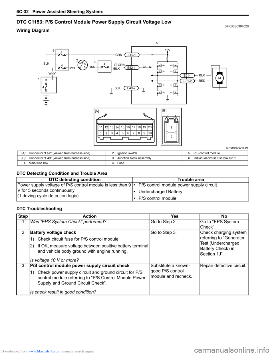
DTC C1153: P/S Control Module Power Supply Circuit Voltage LowS7RS0B6304020
Wiring Diagram
DTC Detecting Condition and Trouble Area
DTC Troubleshooting
MBLK
REDE51-1
E51-2
12V
5
[A ]
12 3
4 5 67
89
11
10
12 13
141516
17 18 19 20
[B ]
1
2
LT GRN
/BLKE52-1 E49-1
GRNGRNWHTBLK
WHY
6
3
4
4
4
4
1 2
E49-2BLK
I7RS0B630011-01
[A]: Connector “E52” (viewed from harness side)
2. Ignition switch5. P/S control module
[B]: Connector “E49” (viewed from harness side) 3. Junction block assembly 6. Individual circuit fuse box No.1
1. Main fuse box 4. Fuse
DTC detecting condition Trouble area
Power supply voltage of P/S control module is less than 9
V for 5 seconds continuously
(1 driving cycle detection logic) • P/S control module power supply circuit
• Undercharged Battery
• P/S control module
Step
Action YesNo
1 Was “EPS System Check” performed? Go to Step 2.Go to “EPS System
Check”.
2 Battery voltage check
1) Check circuit fuse for P/S control module.
2) If OK, measure voltage between positive battery terminal
and vehicle body ground with engine running.
Is voltage 10 V or more? Go to Step 3.
Check charging system
referring to “Generator
Test (Undercharged
Battery Check) in
Section 1J”.
3 P/S control module power supply circuit check
1) Check power supply circuit and ground circuit for P/S
control module referring to “P/S Control Module Power
Supply and Ground Circuit Check”.
Is check result in good condition? Substitute a known-
good P/S control
module and recheck.
Repair defective circuit.
Page 938 of 1496

Downloaded from www.Manualslib.com manuals search engine 7A-2 Heater and Ventilation:
Schematic and Routing Diagram
Heater and Ventilation Wiring Circuit DiagramS7RS0B7102001
2. Ventilator duct 6. Foot air 10. Recirculation air 14. Resistance board
3. Defroster nozzle 7. Front defroster air 11. Center ventilation air 15. Rear duct (if equipped)
4. Heater core 8. Side defroster air 12. Air intake door
BLK
RED/BLK
3
5
7
BLK
2
M
12V
BLU/WHTE23-19
G18-3
G18-4
G18-7
G18-8
G18-10
G18-13
G19-2
G19-3
G19-7
G19-6
G19-1
G18-9
G18-14
BLK/WHT
YEL
BLU/WHT
RED
RED/BLK
RED
GRN
BRN
BLK/RED
RED/YEL
BLK
BLK/YEL
BLK/ORN
4
6
10
8
9
M1
12
11 13
14
15
I4RS0B710002-01
1. Ignition switch 5. Blower motor relay 9. ECM 13. Blower speed selector
2. Blower motor 6. Blower motor resistor 10. Air intake control actuator 14. Air intake selector
3. HVAC control unit 7. Junction block assembly 11. Ind ividual circuit fuse box No.1 15. Rear defogger switch
4. Lighting switch 8. BCM 12. Main fuse box