2008 SUZUKI SWIFT SHIFT LOCK SOLENOID
[x] Cancel search: SHIFT LOCK SOLENOIDPage 684 of 1496
Downloaded from www.Manualslib.com manuals search engine 5A-40 Automatic Transmission/Transaxle:
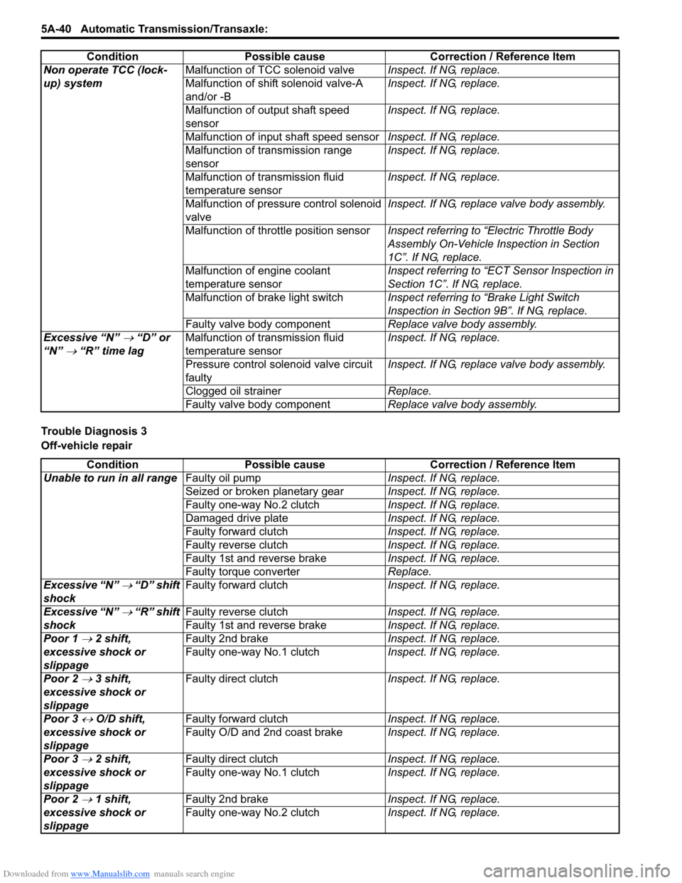
Trouble Diagnosis 3
Off-vehicle repairNon operate TCC (lock-
up) system
Malfunction of TCC solenoid valve
Inspect. If NG, replace.
Malfunction of shift solenoid valve-A
and/or -B Inspect. If NG, replace.
Malfunction of output shaft speed
sensor Inspect. If NG, replace.
Malfunction of input shaft speed sensor Inspect. If NG, replace.
Malfunction of transmission range
sensor Inspect. If NG, replace.
Malfunction of transmission fluid
temperature sensor Inspect. If NG, replace.
Malfunction of pressure control solenoid
valve Inspect. If NG, replace valve body assembly.
Malfunction of throttle position sensor Inspect referring to “Electric Throttle Body
Assembly On-Vehicle Inspection in Section
1C”. If NG, replace.
Malfunction of engine coolant
temperature sensor Inspect referring to “ECT Sensor Inspection in
Section 1C”. If NG, replace.
Malfunction of brake light switch Inspect referring to “Brake Light Switch
Inspection in Section 9B”. If NG, replace.
Faulty valve body component Replace valve body assembly.
Excessive “N”
→ “D” or
“N”
→ “R” time lag Malfunction of transmission fluid
temperature sensor Inspect. If NG, replace.
Pressure control solenoid valve circuit
faulty Inspect. If NG, replace valve body assembly.
Clogged oil strainer Replace.
Faulty valve body component Replace valve body assembly.
Condition Possible cause Correction / Reference Item
Condition
Possible cause Correction / Reference Item
Unable to run in all range Faulty oil pump Inspect. If NG, replace.
Seized or broken planetary gear Inspect. If NG, replace.
Faulty one-way No.2 clutch Inspect. If NG, replace.
Damaged drive plate Inspect. If NG, replace.
Faulty forward clutch Inspect. If NG, replace.
Faulty reverse clutch Inspect. If NG, replace.
Faulty 1st and reverse brake Inspect. If NG, replace.
Faulty torque converter Replace.
Excessive “N”
→ “D” shift
shock Faulty forward clutch
Inspect. If NG, replace.
Excessive “N”
→ “R” shift
shock Faulty reverse clutch
Inspect. If NG, replace.
Faulty 1st and reverse brake Inspect. If NG, replace.
Poor 1
→ 2 shift,
excessive shock or
slippage Faulty 2nd brake
Inspect. If NG, replace.
Faulty one-way No.1 clutch Inspect. If NG, replace.
Poor 2
→ 3 shift,
excessive shock or
slippage Faulty direct clutch
Inspect. If NG, replace.
Poor 3
↔ O/D shift,
excessive shock or
slippage Faulty forward clutch
Inspect. If NG, replace.
Faulty O/D and 2nd coast brake Inspect. If NG, replace.
Poor 3
→ 2 shift,
excessive shock or
slippage Faulty direct clutch
Inspect. If NG, replace.
Faulty one-way No.1 clutch Inspect. If NG, replace.
Poor 2
→ 1 shift,
excessive shock or
slippage Faulty 2nd brake
Inspect. If NG, replace.
Faulty one-way No.2 clutch Inspect. If NG, replace.
Page 686 of 1496
Downloaded from www.Manualslib.com manuals search engine 5A-42 Automatic Transmission/Transaxle:
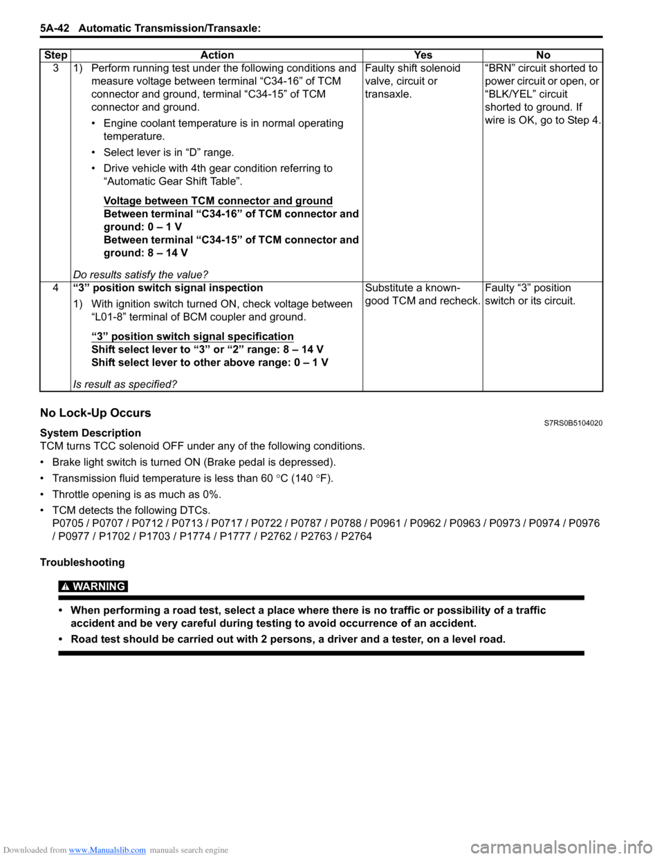
No Lock-Up OccursS7RS0B5104020
System Description
TCM turns TCC solenoid OFF under any of the following conditions.
• Brake light switch is turned ON (Brake pedal is depressed).
• Transmission fluid temperat ure is less than 60 °C (140 °F).
• Throttle opening is as much as 0%.
• TCM detects the following DTCs. P0705 / P0707 / P0712 / P0713 / P0717 / P0722 / P0787 / P0788 / P0961 / P0962 / P0963 / P0973 / P0974 / P0976
/ P0977 / P1702 / P1703 / P1774 / P1777 / P2762 / P2763 / P2764
Troubleshooting
WARNING!
• When performing a road test, select a place where there is no traffic or possibility of a traffic accident and be very careful during testing to avoid occurrence of an accident.
• Road test should be carried out with 2 persons, a driver and a tester, on a level road.
3 1) Perform running test under the following conditions and measure voltage between terminal “C34-16” of TCM
connector and ground, terminal “C34-15” of TCM
connector and ground.
• Engine coolant temperature is in normal operating temperature.
• Select lever is in “D” range.
• Drive vehicle with 4th gear condition referring to “Automatic Gear Shift Table”.
Voltage between TCM connector and ground
Between terminal “C34-16” of TCM connector and
ground: 0 – 1 V
Between terminal “C34-15” of TCM connector and
ground: 8 – 14 V
Do results satisfy the value? Faulty shift solenoid
valve, circuit or
transaxle.
“BRN” circuit shorted to
power circuit or open, or
“BLK/YEL” circuit
shorted to ground. If
wire is OK, go to Step 4.
4 “3” position switch signal inspection
1) With ignition switch turned ON, check voltage between
“L01-8” terminal of BCM coupler and ground.
“3” position switch signal specification
Shift select lever to “3” or “2” range: 8 – 14 V
Shift select lever to other above range: 0 – 1 V
Is result as specified? Substitute a known-
good TCM and recheck.
Faulty “3” position
switch or its circuit.
Step Action Yes No
Page 725 of 1496

Downloaded from www.Manualslib.com manuals search engine Automatic Transmission/Transaxle: 5A-81
2Check TCC lock-up pressure control solenoid valve
resistance
1) Turn ignition switch OFF.
2) Disconnect valve body harness connector (1), (2) on
automatic transaxle.
3) Check for proper connection to solenoid at “WHT/BLU” and “WHT/BLK” circuits.
4) Check resistance of TCC lock-up pressure control
solenoid valve.
TCC lock-up pressure control solenoid valve
resistance
Between shift terminals of transaxle side valve body
harness connector: 5.0 – 5.6 Ω at 20 °C (68 °F)
Between shift terminals of transaxle side valve body
harness connector and transaxle: Infinity
Is check results satisfactory? Go to Step 3. Replace TCC lock-up
pressure control
solenoid valve or lead
wire.
3 Check TCC lock-up pressure control solenoid valve
circuit for ground short
1) Disconnect TCM connectors.
2) Check for proper connection to TCM at terminals “C34-
3” and “C34-5”.
3) If connection is OK, check continuity between terminal
“C34-5” of disconnected harness side TCM connector
and ground, between terminal “C34-3” of disconnected
harness side TCM connector and ground.
Are continuity indicated? “WHT/BLU” or “WHT/
BLK” circuit shorted to
ground.
Intermittent trouble or
faulty TCM.
Check for intermittent
referring to “Intermittent
and Poor Connection
Inspection in Section
00”.
If OK, substitute a
known-good TCM and
recheck.
Step Action Yes No
1
6
7
89
10 5
43 2
1
2
I4RS0A510020-01
Page 732 of 1496
Downloaded from www.Manualslib.com manuals search engine 5A-88 Automatic Transmission/Transaxle:
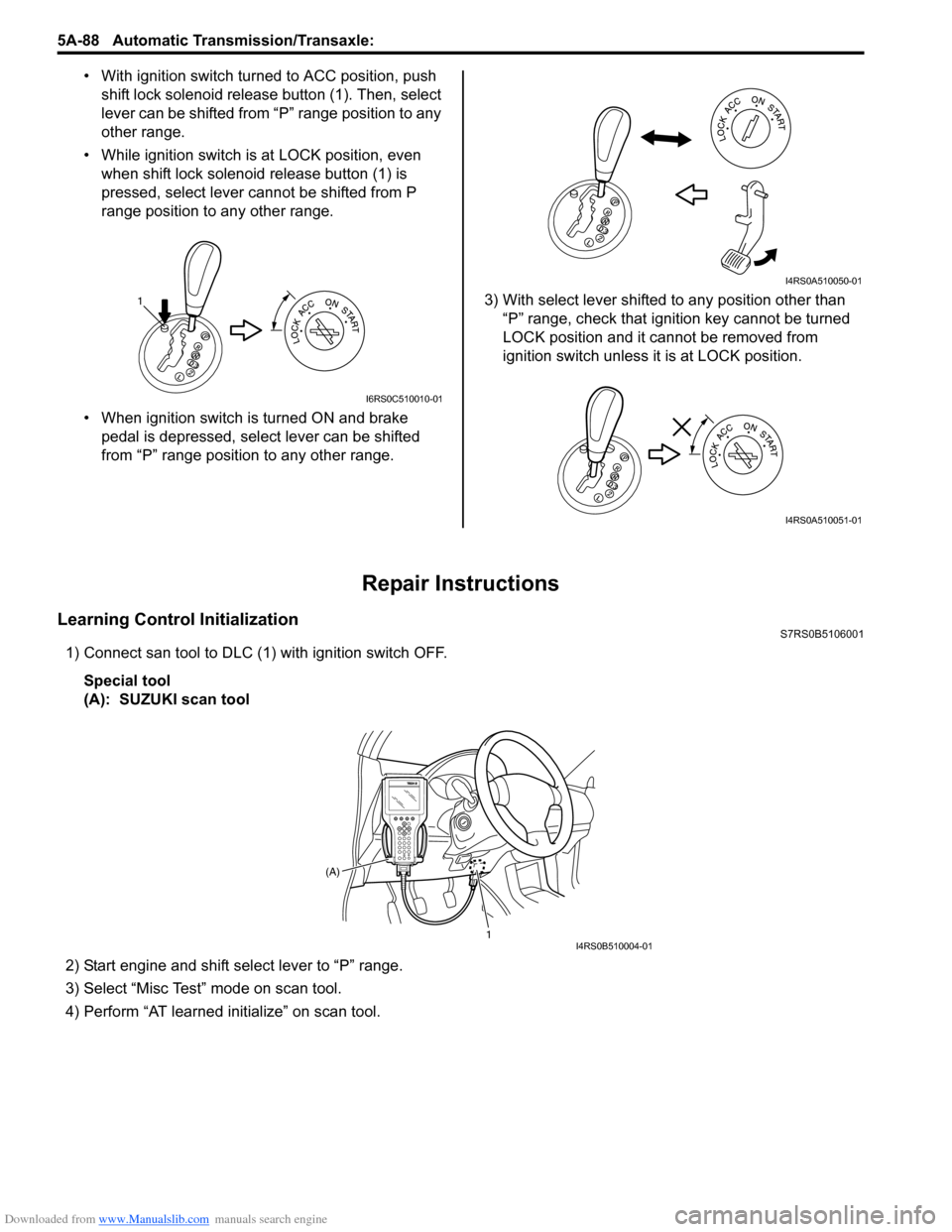
• With ignition switch turned to ACC position, push
shift lock solenoid release button (1). Then, select
lever can be shifted from “P” range position to any
other range.
• While ignition switch is at LOCK position, even when shift lock solenoid release button (1) is
pressed, select lever cannot be shifted from P
range position to any other range.
• When ignition switch is turned ON and brake pedal is depressed, select lever can be shifted
from “P” range position to any other range. 3) With select lever shifted to any position other than
“P” range, check that ignition key cannot be turned
LOCK position and it cannot be removed from
ignition switch unless it is at LOCK position.
Repair Instructions
Learning Control InitializationS7RS0B5106001
1) Connect san tool to DLC (1) with ignition switch OFF.
Special tool
(A): SUZUKI scan tool
2) Start engine and shift select lever to “P” range.
3) Select “Misc Test” mode on scan tool.
4) Perform “AT learned initialize” on scan tool.
1
I6RS0C510010-01
I4RS0A510050-01
I4RS0A510051-01
1
(A)I4RS0B510004-01
Page 734 of 1496
Downloaded from www.Manualslib.com manuals search engine 5A-90 Automatic Transmission/Transaxle:
A/T Fluid ChangeS7RS0B5106003
CAUTION!
Do not use any fluid other than the specified
ATF. Use of any fluid other than the specified
ATF may cause juddering or some other
faulty condition to occur.
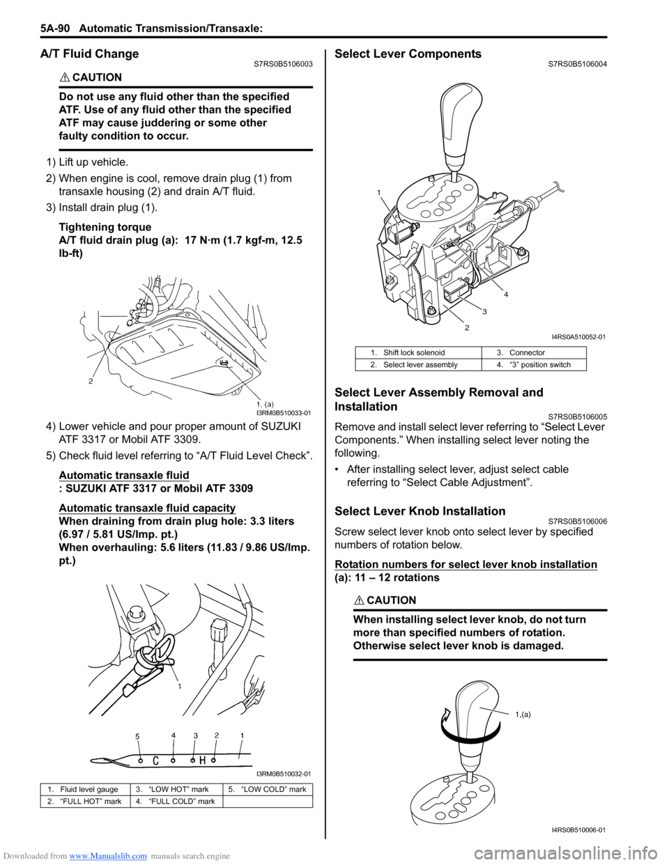
1) Lift up vehicle.
2) When engine is cool, remove drain plug (1) from
transaxle housing (2) and drain A/T fluid.
3) Install drain plug (1).
Tightening torque
A/T fluid drain plug (a): 17 N·m (1.7 kgf-m, 12.5
lb-ft)
4) Lower vehicle and pour proper amount of SUZUKI ATF 3317 or Mobil ATF 3309.
5) Check fluid level referring to “A/T Fluid Level Check”.
Automatic transaxle fluid
: SUZUKI ATF 3317 or Mobil ATF 3309
Automatic transaxle fluid capacity
When draining from drai n plug hole: 3.3 liters
(6.97 / 5.81 US/Imp. pt.)
When overhauling: 5.6 liters (11.83 / 9.86 US/Imp.
pt.)
Select Lever ComponentsS7RS0B5106004
Select Lever Assembly Removal and
Installation
S7RS0B5106005
Remove and install select leve r referring to “Select Lever
Components.” When installing select lever noting the
following.
• After installing select lever, adjust select cable referring to “Select Cable Adjustment”.
Select Lever Knob InstallationS7RS0B5106006
Screw select lever knob onto select lever by specified
numbers of rotation below.
Rotation numbers for select lever knob installation
(a): 11 – 12 rotations
CAUTION!
When installing select lever knob, do not turn
more than specified numbers of rotation.
Otherwise select lever knob is damaged.
1. Fluid level gauge 3. “LOW HOT” mark 5. “LOW COLD” mark
2. “FULL HOT” mark 4. “FULL COLD” mark
I3RM0B510033-01
I3RM0B510032-01
1. Shift lock solenoid 3. Connector
2. Select lever assembly 4. “3” position switch
1
23 4
I4RS0A510052-01
1,(a)
I4RS0B510006-01
Page 735 of 1496
Downloaded from www.Manualslib.com manuals search engine Automatic Transmission/Transaxle: 5A-91
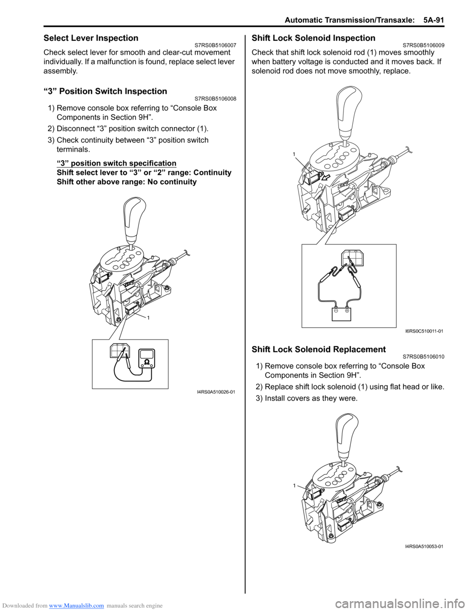
Select Lever InspectionS7RS0B5106007
Check select lever for smooth and clear-cut movement
individually. If a malfunction is found, replace select lever
assembly.
“3” Position Switch InspectionS7RS0B5106008
1) Remove console box referring to “Console Box Components in Section 9H”.
2) Disconnect “3” position switch connector (1).
3) Check continuity between “3” position switch terminals.
“3” position switch specification
Shift select lever to “3 ” or “2” range: Continuity
Shift other above range: No continuity
Shift Lock Solenoid InspectionS7RS0B5106009
Check that shift lock soleno id rod (1) moves smoothly
when battery voltage is conducted and it moves back. If
solenoid rod does not move smoothly, replace.
Shift Lock Solenoid ReplacementS7RS0B5106010
1) Remove console box referring to “Console Box Components in Section 9H”.
2) Replace shift lock solenoid (1) using flat head or like.
3) Install covers as they were.
1
I4RS0A510026-01
1
I6RS0C510011-01
1
I4RS0A510053-01
Page 783 of 1496

Downloaded from www.Manualslib.com manuals search engine Automatic Transmission/Transaxle: 5A-139
2) Install reduction driven gear (1) with special tools and hydraulic press.
Special tool
(A): 09913–84510
(B): 09925–88210 3) Install countershaft LH bearing (1) with special tools
and hydraulic press.
Special tool
(A): 09913–84510
(B): 09925–88210
Valve Body Assembly ComponentsS7RS0B5106052
I2RH0B510213-01
I2RH0B510214-01
I4RS0A510044-01
1. Pressure control solenoid valve 6. Temperature sensor clamp : Apply automatic transaxle fluid.
2. Shift solenoid valve-A (No.1) 7. Valve body assembly: 11 N⋅m (1.1 kgf-m, 8.0 lb-ft)
3. Shift solenoid valve-B (No.2) 8. Manual valve: Do not reuse.
4. TCC pressure control solenoid valve 9. Solenoid lock plate
5. Timing solenoid valve 10. O-ring
Page 784 of 1496

Downloaded from www.Manualslib.com manuals search engine 5A-140 Automatic Transmission/Transaxle:
Valve Body Assembly Disassembly and
Reassembly
S7RS0B5106053
CAUTION!
When replacing pressure control solenoid
valve and/or TCC pressure control solenoid
valve, it is strictly required to replace it
together with valve body assembly as a set.
Replacing pressure control solenoid valve
and/or TCC pressure control solenoid valve
independently may cause excessive shift
shock.
Disassembly1) Pull out manual valve (1).
2) Remove pressure cont rol solenoid valve (1).
3) Remove TCC pressure control solenoid valve (1). 4) Remove shift solenoid valve-A (1).
5) Remove shift solenoid valve-B (1).
6) Remove timing solenoid valve (1).
7) Remove temperature sensor clamp (1).
2. Solenoid lock plate
I2RH0B510216-01
I2RH0B510217-01
1
I4RS0A510045-01
I2RH0B510219-01
I2RH0B510220-01
I2RH0B510221-01
I2RH0B510222-01