2008 SUZUKI SWIFT Lamps
[x] Cancel search: LampsPage 596 of 1496
Downloaded from www.Manualslib.com manuals search engine 4F-22 Electronic Stability Program:
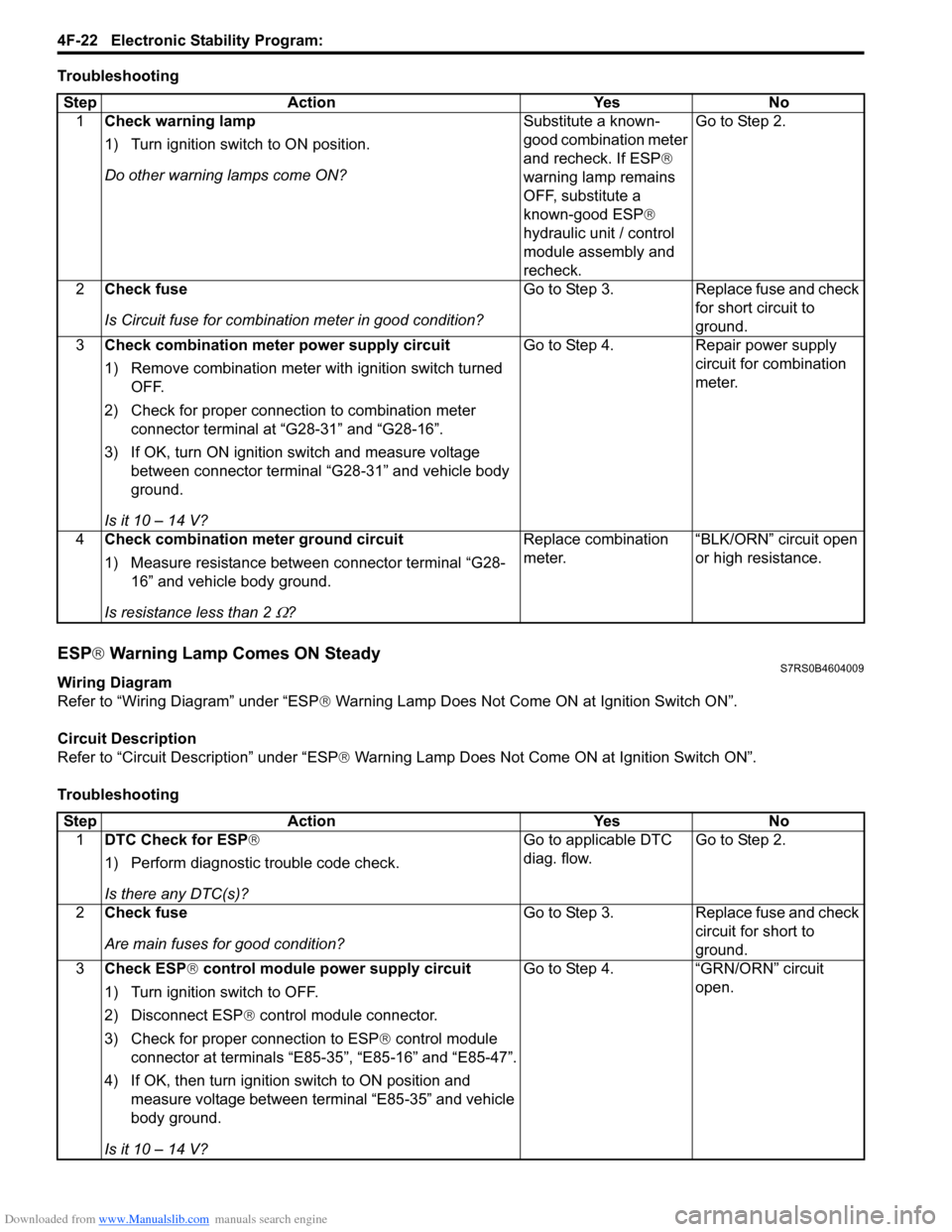
Troubleshooting
ESP® Warning Lamp Comes ON SteadyS7RS0B4604009
Wiring Diagram
Refer to “Wiring Diagram” under “ESP ® Warning Lamp Does Not Come ON at Ignition Switch ON”.
Circuit Description
Refer to “Circuit Description” under “ESP ® Warning Lamp Does Not Come ON at Ignition Switch ON”.
Troubleshooting Step Action Yes No
1 Check warning lamp
1) Turn ignition switch to ON position.
Do other warning lamps come ON? Substitute a known-
good combination meter
and recheck. If ESP®
warning lamp remains
OFF, substitute a
known-good ESP ®
hydraulic unit / control
module assembly and
recheck. Go to Step 2.
2 Check fuse
Is Circuit fuse fo r combination meter in good condition? Go to Step 3. Replace fuse and check
for short circuit to
ground.
3 Check combination meter power supply circuit
1) Remove combination meter wit h ignition switch turned
OFF.
2) Check for proper connection to combination meter connector terminal at “G28-31” and “G28-16”.
3) If OK, turn ON ignition switch and measure voltage between connector terminal “G28-31” and vehicle body
ground.
Is it 10 – 14 V? Go to Step 4. Repair power supply
circuit for combination
meter.
4 Check combination me ter ground circuit
1) Measure resistance between connector terminal “G28- 16” and vehicle body ground.
Is resistance less than 2
Ω? Replace combination
meter.
“BLK/ORN” circuit open
or high resistance.
Step
Action YesNo
1 DTC Check for ESP ®
1) Perform diagnostic trouble code check.
Is there any DTC(s)? Go to applicable DTC
diag. flow.
Go to Step 2.
2 Check fuse
Are main fuses for good condition? Go to Step 3.
Replace fuse and check
circuit for short to
ground.
3 Check ESP ® control module power supply circuit
1) Turn ignition switch to OFF.
2) Disconnect ESP ® control module connector.
3) Check for proper connection to ESP ® control module
connector at terminals “E85-35”, “E85-16” and “E85-47”.
4) If OK, then turn ignition switch to ON position and measure voltage between terminal “E85-35” and vehicle
body ground.
Is it 10 – 14 V? Go to Step 4.
“GRN/ORN” circuit
open.
Page 748 of 1496
Downloaded from www.Manualslib.com manuals search engine 5A-104 Automatic Transmission/Transaxle:
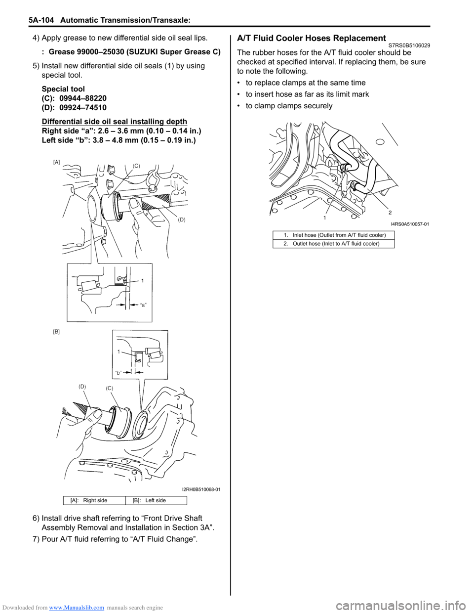
4) Apply grease to new differential side oil seal lips.: Grease 99000–25030 (SUZUKI Super Grease C)
5) Install new differential side oil seals (1) by using special tool.
Special tool
(C): 09944–88220
(D): 09924–74510
Differential side oil seal installing depth
Right side “a”: 2.6 – 3.6 mm (0.10 – 0.14 in.)
Left side “b”: 3.8 – 4.8 mm (0.15 – 0.19 in.)
6) Install drive shaft referring to “Front Drive Shaft Assembly Removal and Installation in Section 3A”.
7) Pour A/T fluid referring to “A/T Fluid Change”.
A/T Fluid Cooler Hoses ReplacementS7RS0B5106029
The rubber hoses for the A/T fluid cooler should be
checked at specified interval. If replacing them, be sure
to note the following.
• to replace clamps at the same time
• to insert hose as far as its limit mark
• to clamp clamps securely
[A]: Right side [B]: Left side
I2RH0B510068-01
1. Inlet hose (Outlet from A/T fluid cooler)
2. Outlet hose (Inlet to A/T fluid cooler)
1 2I4RS0A510057-01
Page 823 of 1496

Downloaded from www.Manualslib.com manuals search engine Manual Transmission/Transaxle: 5B-9
Manual Transaxle Unit Dismounting and
Remounting
S7RS0B5206009
Dismounting1) Drain coolant and transaxle oil.
2) Remove coolant reservoir with reservoir hose.
3) Remove battery and tray.
4) Remove air cleaner case and resonator.
5) Disconnect gear shift and gear select control cables (1) while pressing claws (2) of clip (3).
6) Disconnect back up light switch coupler and undo wiring harness clamps.
7) Remove ground cable from transaxle.
8) Remove clutch operating cylinder with fluid hose from transaxle.
9) Remove water inlet No.2 pipe from transaxle.
10) Remove starting motor re ferring to “Starting Motor
Dismounting and Remounting in Section 1I”.
11) Remove transaxle to engine bolts (1) of upper side. 12) Support engine using supporting device (1).
CAUTION!
Do not apply supporting device to projection
part A. If do so, it may be deformed.
13) Remove front drive shafts and center shaft referring
to “Front Drive Shaft Assembly Removal and
Installation in Section 3A”.
14) Remove exhaust No.2 pipe referring to “Exhaust Pipe and Muffler Removal a nd Installation in Section
1K”.
15) Remove clutch housing lower plate (1).
1
2
3
I7RS0A521003-01
1
1
I4RS0A520018-01
1
A
I4RS0A520019-01
1I4RS0A520020-01
Page 957 of 1496
Downloaded from www.Manualslib.com manuals search engine Air Conditioning System: Manual Type 7B-9
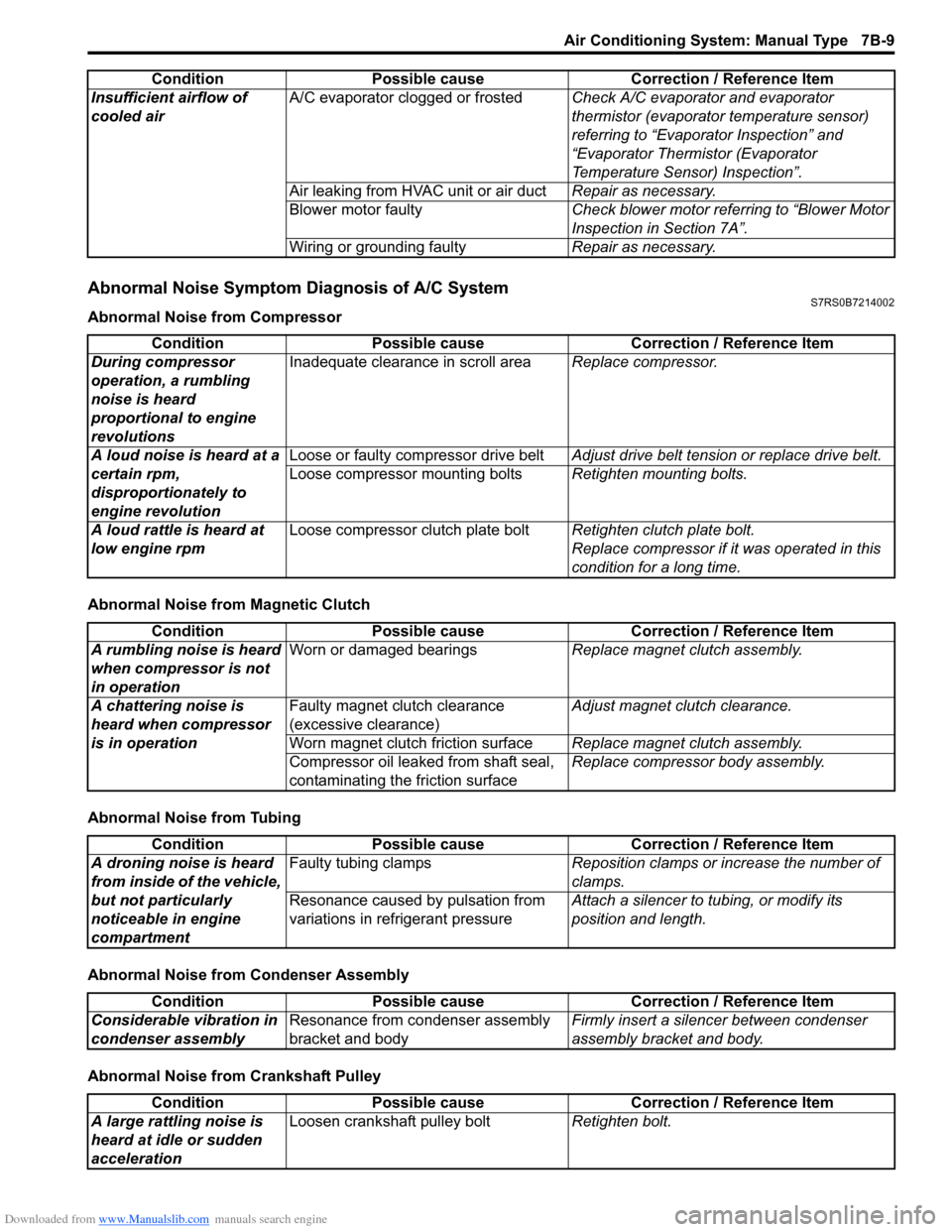
Abnormal Noise Symptom Diagnosis of A/C SystemS7RS0B7214002
Abnormal Noise from Compressor
Abnormal Noise from Magnetic Clutch
Abnormal Noise from Tubing
Abnormal Noise from Condenser Assembly
Abnormal Noise from Crankshaft PulleyInsufficient airflow of
cooled air
A/C evaporator clogged or frosted
Check A/C evaporator and evaporator
thermistor (evaporator temperature sensor)
referring to “Evaporator Inspection” and
“Evaporator Thermistor (Evaporator
Temperature Sensor) Inspection”.
Air leaking from HVAC unit or air duct Repair as necessary.
Blower motor faulty Check blower motor referring to “Blower Motor
Inspection in Section 7A”.
Wiring or grounding faulty Repair as necessary.
Condition Possible cause Correction / Reference Item
Condition
Possible cause Correction / Reference Item
During compressor
operation, a rumbling
noise is heard
proportional to engine
revolutions Inadequate clearance in scroll area
Replace compressor.
A loud noise is heard at a
certain rpm,
disproportionately to
engine revolution Loose or faulty compressor drive belt
Adjust drive belt tension or replace drive belt.
Loose compressor mounting bolts Retighten mounting bolts.
A loud rattle is heard at
low engine rpm Loose compressor clutch plate bolt
Retighten clutch plate bolt.
Replace compressor if it was operated in this
condition for a long time.
Condition Possible cause Correction / Reference Item
A rumbling noise is heard
when compressor is not
in operation Worn or damaged bearings
Replace magnet clutch assembly.
A chattering noise is
heard when compressor
is in operation Faulty magnet clutch clearance
(excessive clearance)
Adjust magnet clutch clearance.
Worn magnet clutch friction surface Replace magnet clutch assembly.
Compressor oil leaked from shaft seal,
contaminating the friction surface Replace compressor body assembly.
Condition
Possible cause Correction / Reference Item
A droning noise is heard
from inside of the vehicle,
but not particularly
noticeable in engine
compartment Faulty tubing clamps
Reposition clamps or increase the number of
clamps.
Resonance caused by pulsation from
variations in re frigerant pressure Attach a silencer to tubing, or modify its
position and length.
Condition
Possible cause Correction / Reference Item
Considerable vibration in
condenser assembly Resonance from condenser assembly
bracket and body Firmly insert a silenc
er between condenser
assembly bracket and body.
Condition Possible cause Correction / Reference Item
A large rattling noise is
heard at idle or sudden
acceleration Loosen crankshaft pulley bolt
Retighten bolt.
Page 1135 of 1496
Downloaded from www.Manualslib.com manuals search engine Air Bag System: 8B-97
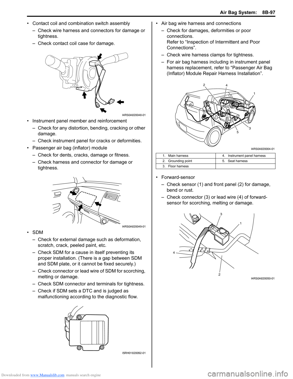
• Contact coil and combination switch assembly
– Check wire harness and connectors for damage or tightness.
– Check contact coil case for damage.
• Instrument panel member and reinforcement – Check for any distortion, bending, cracking or other damage.
– Check instrument panel fo r cracks or deformities.
• Passenger air bag (inflator) module
– Check for dents, cracks, damage or fitness.
– Check harness and connector for damage or tightness.
•SDM – Check for external damage such as deformation, scratch, crack, peeled paint, etc.
– Check SDM for a cause in itself preventing its proper installation. (There is a gap between SDM
and SDM plate, or it cannot be fixed securely.)
– Check connector or lead wire of SDM for scorching, melting or damage.
– Check SDM connector and terminals for tightness.
– Check if SDM sets a DTC and is judged as malfunctioning according to the diagnostic flow. • Air bag wire harness and connections
– Check for damages, deformities or poor connections.
Refer to “Inspection of Intermittent and Poor
Connections”.
– Check wire harness clamps for tightness.
– For air bag harness including in instrument panel harness replacement, refer to “Passenger Air Bag
(Inflator) Module Repair Harness Installation”.
• Forward-sensor – Check sensor (1) and front panel (2) for damage, bend or rust.
– Check connector (3) or lead wire (4) of forward- sensor for scorching, melting or damage.
I4RS0A820048-01
I4RS0A820049-01
I5RH01820092-01
1. Main harness 4. Instrument panel harness
2. Grounding point 5. Seat harness
3. Floor harness
1
2
3
4
5
I4RS0A820004-01
1
3
2
4
I4RS0A820050-01
Page 1139 of 1496
Downloaded from www.Manualslib.com manuals search engine Air Bag System: 8B-101
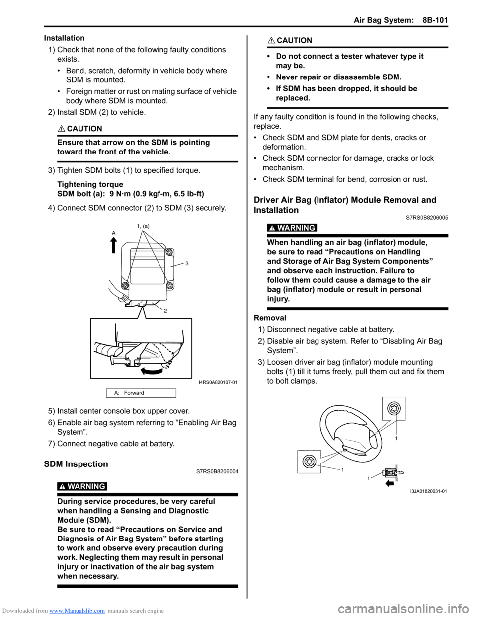
Installation1) Check that none of the following faulty conditions exists.
• Bend, scratch, deformity in vehicle body where SDM is mounted.
• Foreign matter or rust on mating surface of vehicle body where SDM is mounted.
2) Install SDM (2) to vehicle.
CAUTION!
Ensure that arrow on the SDM is pointing
toward the front of the vehicle.
3) Tighten SDM bolts (1) to specified torque.
Tightening torque
SDM bolt (a): 9 N·m (0.9 kgf-m, 6.5 lb-ft)
4) Connect SDM connector (2) to SDM (3) securely.
5) Install center console box upper cover.
6) Enable air bag system referring to “Enabling Air Bag System”.
7) Connect negative cable at battery.
SDM InspectionS7RS0B8206004
WARNING!
During service procedures, be very careful
when handling a Sensing and Diagnostic
Module (SDM).
Be sure to read “Precautions on Service and
Diagnosis of Air Bag System” before starting
to work and observe every precaution during
work. Neglecting them ma y result in personal
injury or inactivation of the air bag system
when necessary.
CAUTION!
• Do not connect a tester whatever type it may be.
• Never repair or disassemble SDM.
• If SDM has been dropped, it should be replaced.
If any faulty condition is fo und in the following checks,
replace.
• Check SDM and SDM plate for dents, cracks or deformation.
• Check SDM connector for damage, cracks or lock mechanism.
• Check SDM terminal for bend, corrosion or rust.
Driver Air Bag (Inflator) Module Removal and
Installation
S7RS0B8206005
WARNING!
When handling an air bag (inflator) module,
be sure to read “Precautions on Handling
and Storage of Air Bag System Components”
and observe each instruction. Failure to
follow them could cause a damage to the air
bag (inflator) module or result in personal
injury.
Removal 1) Disconnect negative cable at battery.
2) Disable air bag system. Re fer to “Disabling Air Bag
System”.
3) Loosen driver air bag (inflator) module mounting bolts (1) till it turns freely, pull them out and fix them
to bolt clamps.
A: Forward
2 3
A
1, (a)
I4RS0A820107-01
I3JA01820031-01