2008 SUZUKI SWIFT Electrical Circuit Inspection Procedure
[x] Cancel search: Electrical Circuit Inspection ProcedurePage 1401 of 1496
Downloaded from www.Manualslib.com manuals search engine Table of Contents 10- i
10
Section 10
CONTENTS
Control Systems
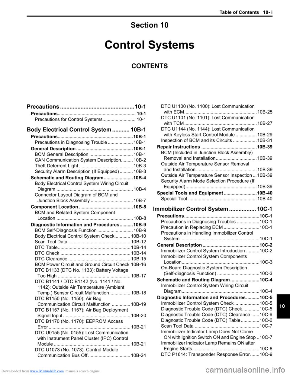
Precautions ............................................... 10-1
Precautions........................................................... 10-1
Precautions for Control Systems......................... 10-1
Body Electrical Contro l System ........... 10B-1
Precautions......................................................... 10B-1
Precautions in Diagnosing Trouble ................... 10B-1
General Description ........................................... 10B-1 BCM General Description ................................. 10B-1
CAN Communication System Description......... 10B-2
Theft Deterrent Light ......................................... 10B-3
Security Alarm Description (If Equipped) .......... 10B-3
Schematic and Routing Diagram ...................... 10B-4 Body Electrical Control System Wiring Circuit Diagram .......................................................... 10B-4
Connector Layout Diagram of BCM and Junction Block Assembly ................................ 10B-7
Component Locatio n ......................................... 10B-8
BCM and Related System Component Location .......................................................... 10B-8
Diagnostic Information an d Procedures .......... 10B-9
BCM Self-Diagnosis Function ........................... 10B-9
Body Electrical Control System Check............ 10B-10
Scan Tool Data ............................................... 10B-12
DTC Table ....................................................... 10B-14
DTC Check ..................................................... 10B-14
DTC Clearance ............................................... 10B-15
BCM Power Circuit and Ground Circuit Check 10B-16
DTC B1133 (DTC No. 1133): Battery Voltage Too High ....................................................... 10B-17
DTC B1141 / DTC B1142 (No. 1141 / No. 1142): Outside Air Temperature (Ambient
Temp.) Sensor Circuit Ma lfunction ................ 10B-18
DTC B1150 (No. 1150): Air Bag Communication Circuit Malfunction .............. 10B-19
DTC B1157 (No. 1157): Air Bag Deployment Signal Input ................................................... 10B-20
DTC B1170 (No. 1170 ): EEPROM Access
Error .............................................................. 10B-21
DTC U0155 (No. 0155): Lost Communication with Instrument Panel Cluster (IPC) Control
Module .......................................................... 10B-21
DTC U1073 (No. 1073): Control Module Communication Bus Off ................................ 10B-24 DTC U1100 (No. 1100): Lost Communication
with ECM ....................................................... 10B-25
DTC U1101 (No. 1101): Lost Communication with TCM ....................................................... 10B-27
DTC U1144 (No. 1144): Lost Communication with Keyless Start Control Module ................ 10B-29
Inspection of BCM and its Circuits .................. 10B-31
Repair Instructions ........... ...............................10B-39
BCM (Included in Junction Block Assembly) Removal and Installation ............................... 10B-39
Outside Air Temperature Sensor Removal and Installation .............................................. 10B-39
Outside Air Temperature Sensor Inspection ... 10B-39
Security Alarm Mode Selection Procedure (If Equipped) ...................................................... 10B-39
Special Tools and Equipmen t .........................10B-40
Special Tool .................................................... 10B-40
Immobilizer Control Syst em ................. 10C-1
Precautions.........................................................10C-1
Precautions in Diagnosing Troubles .................10C-1
Precaution in Replacing ECM ...........................10C-1
Precautions in Handli ng Immobilizer Control
System ............................................................10C-1
General Description ...........................................10C-2 Immobilizer Control System Introduction ..........10C-2
Immobilizer Control System Components Location...........................................................10C-3
On-Board Diagnostic System Description (Self-diagnosis Function) ................................10C-3
Schematic and Routing Diag ram ......................10C-4
Immobilizer Control System Wiring Circuit Diagram...........................................................10C-4
Diagnostic Information an d Procedures ..........10C-5
Immobilizer Control System Check ...................10C-5
Diagnostic Trouble Code (DTC) Check.............10C-5
Diagnostic Trouble Code (DTC) Clearance ......10C-6
Diagnostic Trouble Code (DTC) Table ..............10C-6
Scan Tool Data .................................................10C-7
Immobilizer Indicator Lamp Does Not Come ON with Ignition Switch ON and Engine Stop ..10C-7
Immobilizer Indicator Lamp Remains ON after Engine Starts...................................................10C-8
DTC P1614: Transponder Re sponse Error .......10C-9
Page 1427 of 1496
Downloaded from www.Manualslib.com manuals search engine Body Electrical Control System: 10B-24
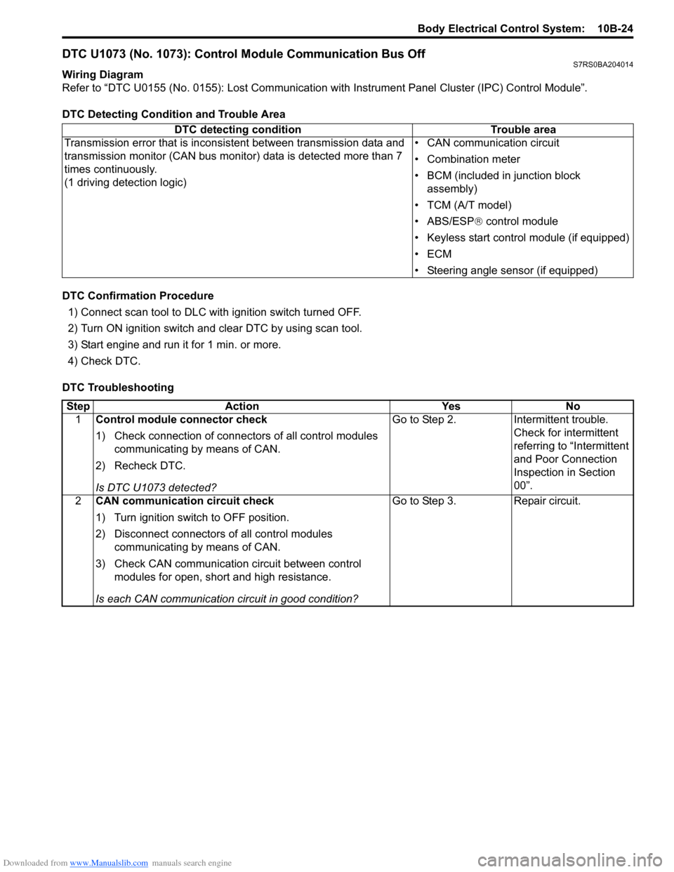
DTC U1073 (No. 1073): Control Module Communication Bus OffS7RS0BA204014
Wiring Diagram
Refer to “DTC U0155 (No. 0155): Lost Communication with Instrument Panel Cluster (IPC) Control Module”.
DTC Detecting Condition and Trouble Area
DTC Confirmation Procedure 1) Connect scan tool to DLC with ignition switch turned OFF.
2) Turn ON ignition switch and clear DTC by using scan tool.
3) Start engine and run it for 1 min. or more.
4) Check DTC.
DTC Troubleshooting DTC detecting condition Trouble area
Transmission error that is inconsistent between transmission data and
transmission monitor (CAN bus monitor) data is detected more than 7
times continuously.
(1 driving detection logic) • CAN communication circuit
• Combination meter
• BCM (included in junction block
assembly)
• TCM (A/T model)
• ABS/ESP ® control module
• Keyless start control module (if equipped)
•ECM
• Steering angle sensor (if equipped)
Step Action YesNo
1 Control module connector check
1) Check connection of connectors of all control modules
communicating by means of CAN.
2) Recheck DTC.
Is DTC U1073 detected? Go to Step 2.
Intermittent trouble.
Check for intermittent
referring to “Intermittent
and Poor Connection
Inspection in Section
00”.
2 CAN communication circuit check
1) Turn ignition switch to OFF position.
2) Disconnect connectors of all control modules
communicating by means of CAN.
3) Check CAN communication circuit between control modules for open, short and high resistance.
Is each CAN communication circuit in good condition? Go to Step 3.
Repair circuit.
Page 1432 of 1496
Downloaded from www.Manualslib.com manuals search engine 10B-29 Body Electrical Control System:
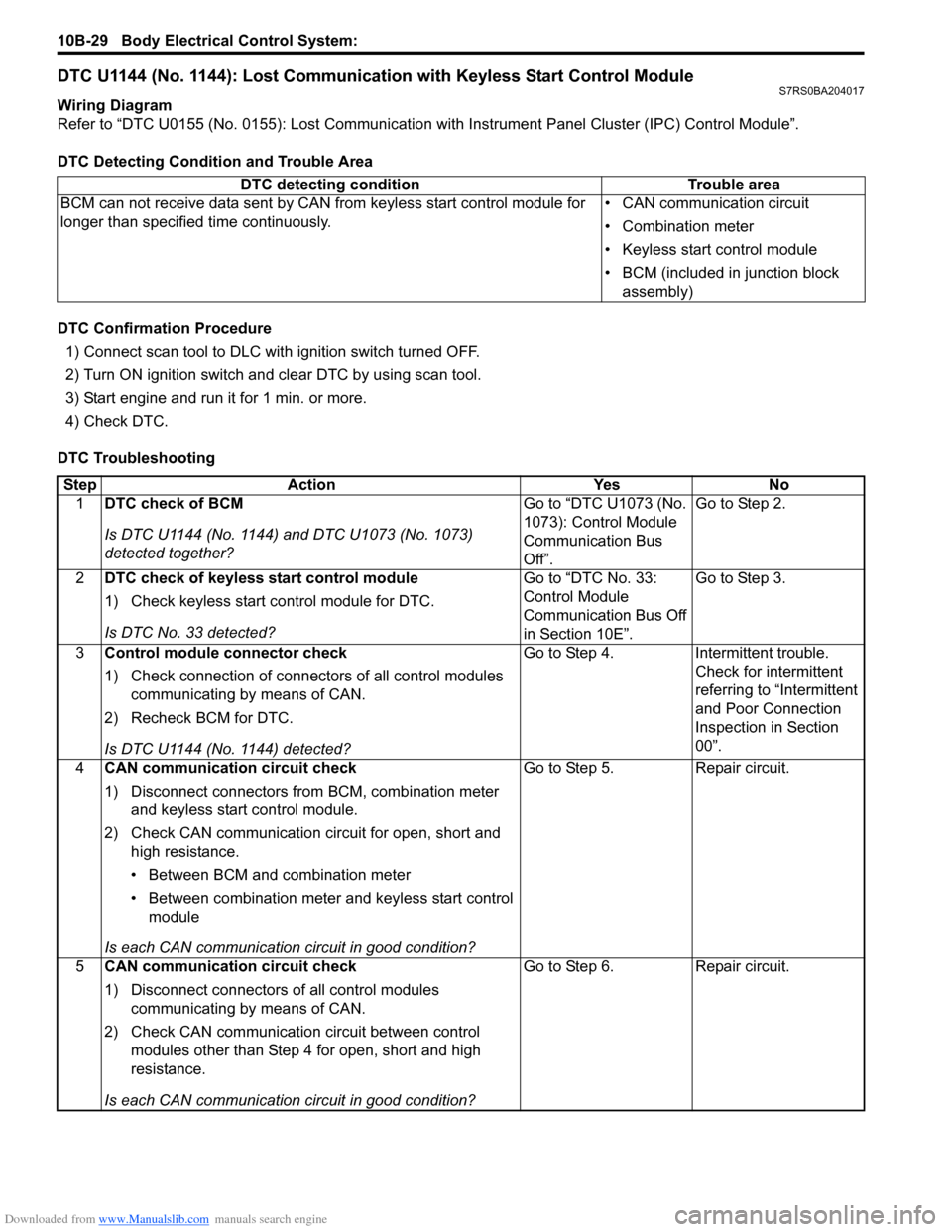
DTC U1144 (No. 1144): Lost Communication with Keyless Start Control ModuleS7RS0BA204017
Wiring Diagram
Refer to “DTC U0155 (No. 0155): Lost Communication with Instrument Panel Cluster (IPC) Control Module”.
DTC Detecting Condition and Trouble Area
DTC Confirmation Procedure 1) Connect scan tool to DLC with ignition switch turned OFF.
2) Turn ON ignition switch and clear DTC by using scan tool.
3) Start engine and run it for 1 min. or more.
4) Check DTC.
DTC Troubleshooting DTC detecting condition Trouble area
BCM can not receive data sent by CAN from keyless start control module for
longer than specified time continuously. • CAN communication circuit
• Combination meter
• Keyless start control module
• BCM (included in junction block
assembly)
Step Action YesNo
1 DTC check of BCM
Is DTC U1144 (No. 1144) and DTC U1073 (No. 1073)
detected together? Go to “DTC U1073 (No.
1073): Control Module
Communication Bus
Off”.Go to Step 2.
2 DTC check of keyless start control module
1) Check keyless start co ntrol module for DTC.
Is DTC No. 33 detected? Go to “DTC No. 33:
Control Module
Communication Bus Off
in Section 10E”.Go to Step 3.
3 Control module connector check
1) Check connection of connectors of all control modules
communicating by means of CAN.
2) Recheck BCM for DTC.
Is DTC U1144 (No. 1144) detected? Go to Step 4.
Intermittent trouble.
Check for intermittent
referring to “Intermittent
and Poor Connection
Inspection in Section
00”.
4 CAN communication circuit check
1) Disconnect connectors from BCM, combination meter
and keyless start control module.
2) Check CAN communication circuit for open, short and high resistance.
• Between BCM and combination meter
• Between combination meter and keyless start control module
Is each CAN communication circuit in good condition? Go to Step 5.
Repair circuit.
5 CAN communication circuit check
1) Disconnect connectors of all control modules
communicating by means of CAN.
2) Check CAN communication circuit between control modules other than Step 4 for open, short and high
resistance.
Is each CAN communication circuit in good condition? Go to Step 6.
Repair circuit.
Page 1444 of 1496
Downloaded from www.Manualslib.com manuals search engine 10C-1 Immobilizer Control System:
Control Systems
Immobilizer Control System
Precautions
Precautions in Diagnosing TroublesS7RS0BA300001
• Before confirming the diagnostic trouble code (DTC),
do not disconnect connector from ECM, battery cable
from battery, ground wire harness, or main fuse. Such
disconnection will erase DTC stored in ECM.
• DTC stored in ECM memory can be checked as well as cleared by using SUZUKI scan tool. Before using
SUZUKI scan tool, read its operator’s manual
carefully to know how to use it and what functions are
available.
• Be sure to read “Precautions for Electrical Circuit Service in Section 00” before inspection.
• Communication of ECM, BCM, keyless start control module (if equipped), ABS / ESP ® control module,
steering angle sensor (ESP ® model), combination
meter and TCM (A/T model) is established by CAN
(Controller Area Network). Therefore, handle CAN
communication lines with care referring to “Precaution
for CAN Communication System in Section 00”. For
CAN communication system, refer to description on
“CAN Communication System Description in Section
1A”.
Precaution in Replacing ECMS7RS0BA300002
• If ECM is replaced with new or used one without immobilizer control function , the engine will not be
started. In case of the above, check if the newly
installed ECM has immobilizer control function.
• After ECM is replaced with new one or used one, the transponder code in the transponder built in the
ignition key has to be registered with ECM. Or, the
engine cannot be started up. For the registration
procedure, refer to “Procedure after ECM
Replacement”.
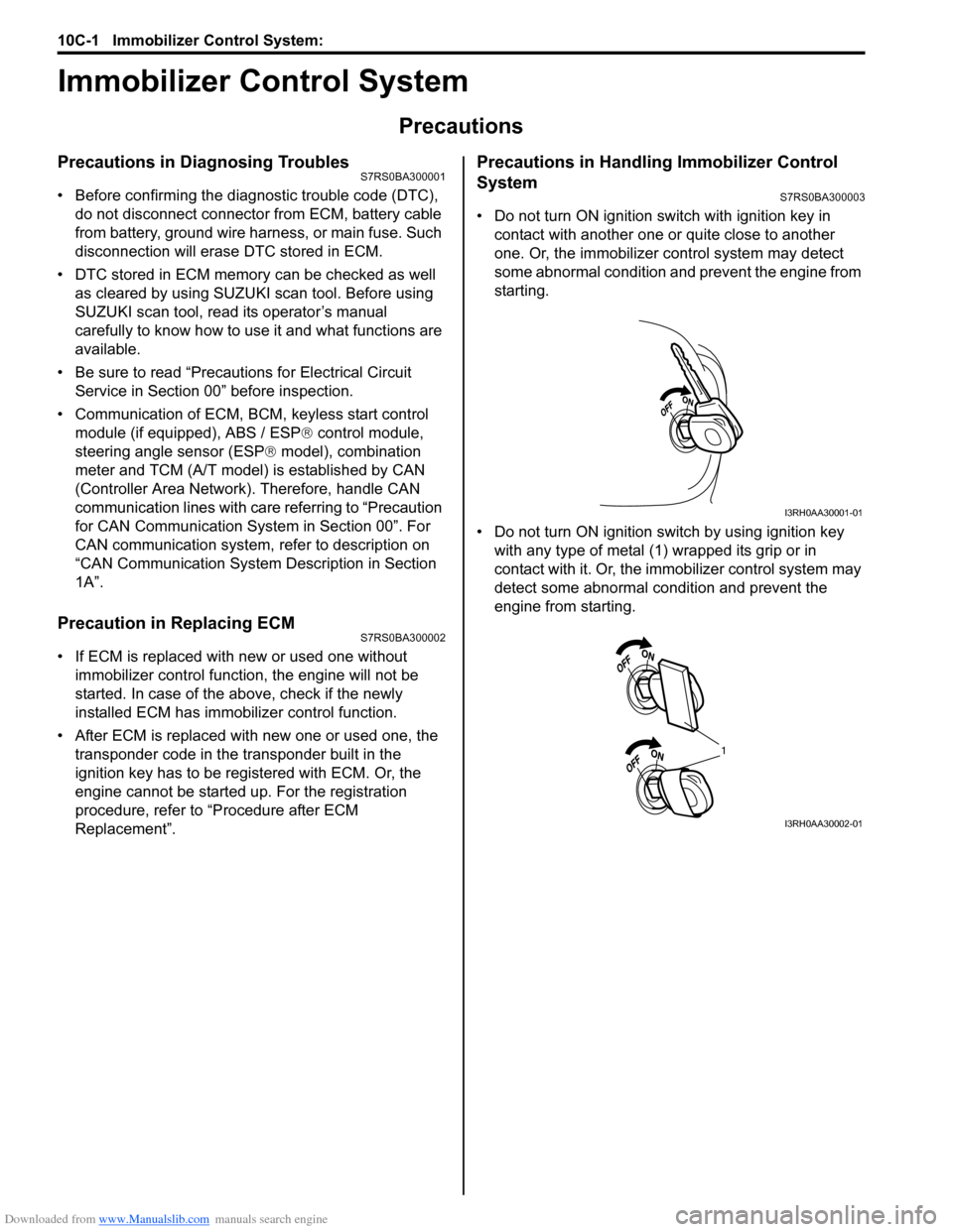
Precautions in Handling Immobilizer Control
System
S7RS0BA300003
• Do not turn ON ignition sw itch with ignition key in
contact with another one or quite close to another
one. Or, the immobilizer co ntrol system may detect
some abnormal condition and prevent the engine from
starting.
• Do not turn ON ignition switch by using ignition key with any type of metal (1) wrapped its grip or in
contact with it. Or, the i mmobilizer control system may
detect some abnormal condition and prevent the
engine from starting.
I3RH0AA30001-01
1
I3RH0AA30002-01
Page 1470 of 1496
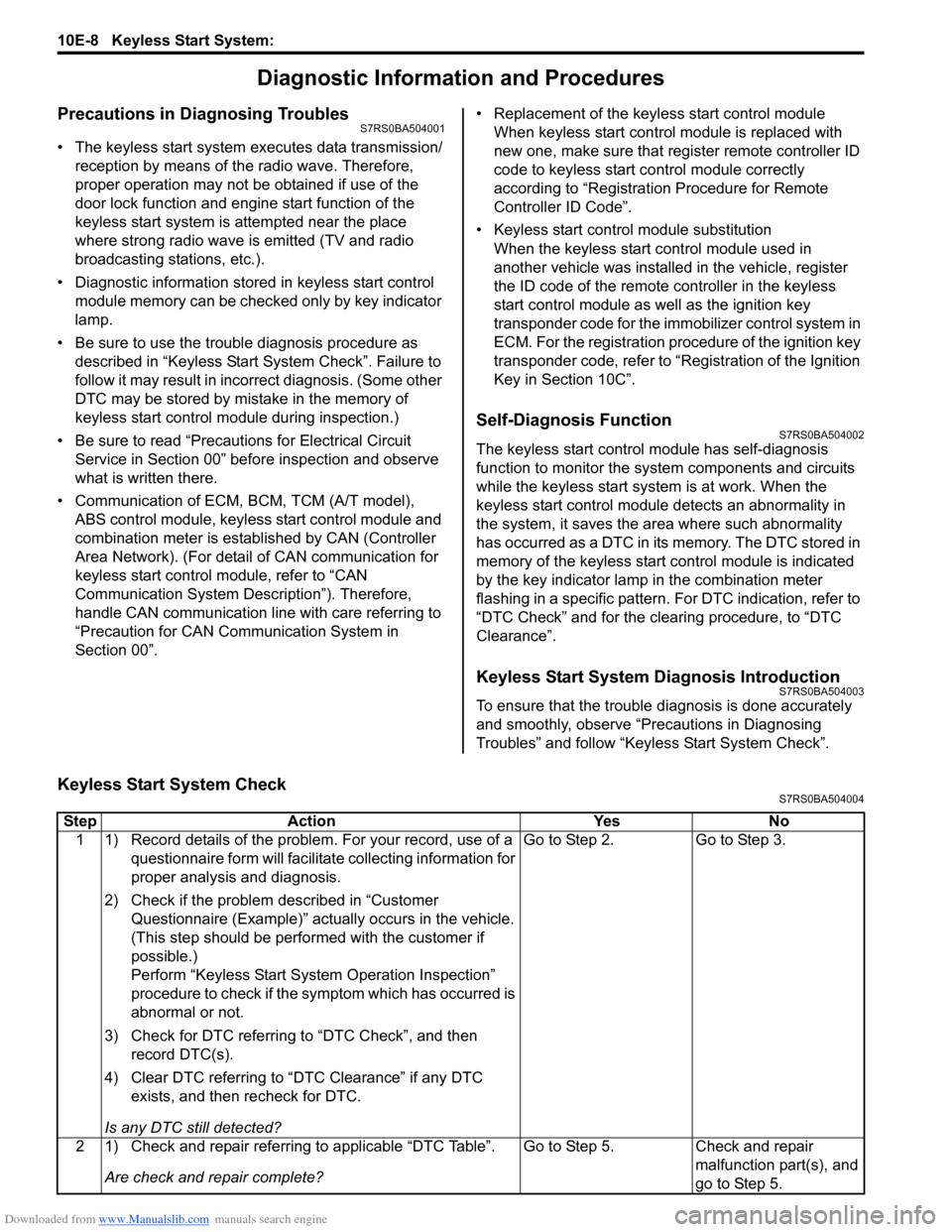
Downloaded from www.Manualslib.com manuals search engine 10E-8 Keyless Start System:
Diagnostic Information and Procedures
Precautions in Diagnosing TroublesS7RS0BA504001
• The keyless start system executes data transmission/reception by means of th e radio wave. Therefore,
proper operation may not be obtained if use of the
door lock function and engine start function of the
keyless start system is attempted near the place
where strong radio wave is emitted (TV and radio
broadcasting stations, etc.).
• Diagnostic information stored in keyless start control
module memory can be checked only by key indicator
lamp.
• Be sure to use the trouble diagnosis procedure as described in “Keyless Start System Check”. Failure to
follow it may result in incorrect diagnosis. (Some other
DTC may be stored by mistake in the memory of
keyless start control module during inspection.)
• Be sure to read “Precautions for Electrical Circuit Service in Section 00” befo re inspection and observe
what is written there.
• Communication of ECM, BCM, TCM (A/T model), ABS control module, keyless start control module and
combination meter is estab lished by CAN (Controller
Area Network). (For detail of CAN communication for
keyless start control module, refer to “CAN
Communication System Description”). Therefore,
handle CAN communication line with care referring to
“Precaution for CAN Communication System in
Section 00”. • Replacement of the keyless start control module
When keyless start control module is replaced with
new one, make sure that r egister remote controller ID
code to keyless start co ntrol module correctly
according to “Registration Procedure for Remote
Controller ID Code”.
• Keyless start control module substitution When the keyless start control module used in
another vehicle was installed in the vehicle, register
the ID code of the remote controller in the keyless
start control module as well as the ignition key
transponder code fo r the immobilizer control system in
ECM. For the registration procedure of the ignition key
transponder code, refer to “Registration of the Ignition
Key in Section 10C”.
Self-Diagnosis FunctionS7RS0BA504002
The keyless start control module has self-diagnosis
function to monitor the system components and circuits
while the keyless start system is at work. When the
keyless start control module detects an abnormality in
the system, it saves the ar ea where such abnormality
has occurred as a DTC in its memory. The DTC stored in
memory of the keyless start control module is indicated
by the key indicator lamp in the combination meter
flashing in a specific pattern. For DTC indication, refer to
“DTC Check” and for the clearing procedure, to “DTC
Clearance”.
Keyless Start System Diagnosis IntroductionS7RS0BA504003
To ensure that the trouble diagnosis is done accurately
and smoothly, observe “Precautions in Diagnosing
Troubles” and follow “Keyless Start System Check”.
Keyless Start System CheckS7RS0BA504004
Step Action YesNo
1 1) Record details of the problem. For your record, use of a questionnaire form will facilit ate collecting information for
proper analysis and diagnosis.
2) Check if the problem described in “Customer Questionnaire (Example)” actually occurs in the vehicle.
(This step should be performed with the customer if
possible.)
Perform “Keyless Start System Operation Inspection”
procedure to check if the symptom which has occurred is
abnormal or not.
3) Check for DTC referring to “DTC Check”, and then record DTC(s).
4) Clear DTC referring to “DTC Clearance” if any DTC exists, and then recheck for DTC.
Is any DTC still detected? Go to Step 2.
Go to Step 3.
2 1) Check and repair referring to applicable “DTC Table”. Are check and repair complete? Go to Step 5.
Check and repair
malfunction part(s), and
go to Step 5.