2008 SUZUKI SWIFT Charging system
[x] Cancel search: Charging systemPage 422 of 1496
Downloaded from www.Manualslib.com manuals search engine 1J-12 Charging System:
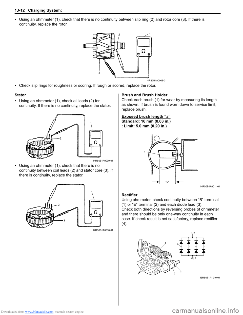
• Using an ohmmeter (1), check that there is no continuity between slip ring (2) and rotor core (3). If there is
continuity, replace the rotor.
• Check slip rings for roughness or scoring. If rough or scored, replace the rotor.
Stator
• Using an ohmmeter (1), check all leads (2) for continuity. If there is no co ntinuity, replace the stator.
• Using an ohmmeter (1), check that there is no continuity between coil leads (2) and stator core (3). If
there is continuity, replace the stator. Brush and Brush Holder
Check each brush (1) for wear by measuring its length
as shown. If brush is found worn down to service limit,
replace brush.
Exposed brush length “a”
Standard: 16 mm (0.63 in.)
: Limit: 5.0 mm (0.20 in.)
Rectifier
Using ohmmeter, check continuity between “B” terminal
(1) or “E” terminal (2) and each diode lead (3).
Check both directions by reversing probes of ohmmeter
and there should be only one-way continuity in each
case. If check result is not satisfactory, replace rectifier
(4).
I4RS0B1A0008-01
I4RS0B1A0009-01
I4RS0B1A0010-01
I4RS0B1A0011-01
1
1
3 3
2
2
4
I6RS0B1A1010-01
Page 423 of 1496
Downloaded from www.Manualslib.com manuals search engine Charging System: 1J-13
Specifications
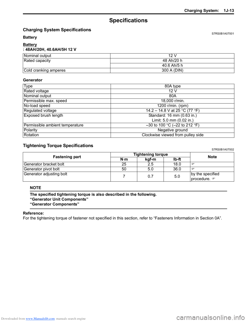
Charging System SpecificationsS7RS0B1A07001
Battery
Battery
: 48AH/20H, 40.6AH/5H 12 V
Generator
Tightening Torque SpecificationsS7RS0B1A07002
NOTE
The specified tightening torque is also described in the following.
“Generator Unit Components”
“Generator Components”
Reference:
For the tightening torque of fastener not specified in this section, refer to “Fasteners Information in Section 0A”.
Nominal output
12 V
Rated capacity 48 Ah/20 h
40.6 Ah/5 h
Cold cranking amperes 300 A (DIN)
Ty p e 80A type
Rated voltage 12 V
Nominal output 80A
Permissible max. speed 18,000 r/min.
No-load speed 1200 r/min. (rpm)
Regulated voltage 14.2 – 14.8 V at 25 ° C (77 °F)
Exposed brush length Standard: 16 mm (0.63 in.)
Limit: 5.0 mm (0.02 in.)
Permissible ambient temperature –30 to 100 °C (–22 to 212 °F)
Polarity Negative ground
Rotation Clockwise viewed from pulley side
Fastening partTightening torque
Note
N ⋅mkgf-mlb-ft
Generator bracket bolt 25 2.5 18.0 �)
Generator pivot bolt 50 5.0 36.0 �)
Generator adjusting bolt 70.7 5.0by the specified
procedure.
�)
Page 516 of 1496
Downloaded from www.Manualslib.com manuals search engine 4A-18 Brake Control System and Diagnosis:
10) Check pedal height and play referring to “Brake Pedal Free Height Inspection” and “Brake Pedal
Play Inspection”.
11) Check each installed part for fluid leakage and perform brake test.
12) Evacuate and charge refrigerant by referring to “Evacuating of A/C Syst em” and “Procedure of
Charging” under “Operation Procedure for
Refrigerant Charge in Section 7B” or “Operation
Procedure for Refrigerant Charge in Section 7B”.
Brake Booster Inspection and AdjustmentS7RS0B4106018
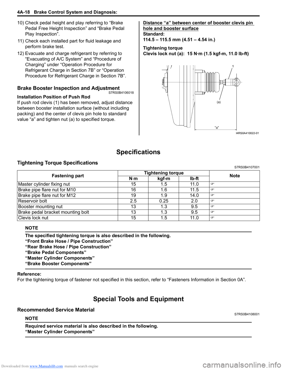
Installation Position of Push Rod
If push rod clevis (1) has b een removed, adjust distance
between booster installation surface (without including
packing) and the center of clevis pin hole to standard
value “a” and tighten nut (a) to specified torque. Distance “a” between center of booster clevis pin
hole and booster surface
Standard:
114.5 – 115.5 mm (4.51 – 4.54 in.)
Tightening torque
Clevis lock nut (a): 15 N·m (1.5 kgf-m, 11.0 lb-ft)
Specifications
Tightening Torque SpecificationsS7RS0B4107001
NOTE
The specified tightening torque is also described in the following.
“Front Brake Hose / Pipe Construction”
“Rear Brake Hose / Pipe Construction”
“Brake Pedal Components”
“Master Cylinder Components”
“Brake Booster Components”
Reference:
For the tightening torque of fastener not specified in this
section, refer to “Fasteners Information in Section 0A”.
Special Tools and Equipment
Recommended Service MaterialS7RS0B4108001
NOTE
Required service material is also described in the following.
“Master Cylinder Components”
I4RS0A410022-01
Fastening part Tightening torque
Note
N ⋅mkgf-mlb-ft
Master cylinder fixing nut 15 1.5 11.0 �)
Brake pipe flare nut for M10 16 1.6 11.5 �)
Brake pipe flare nut for M12 19 1.9 14.0 �)
Reservoir bolt 2.5 0.25 2.0 �)
Booster mounting nut 13 1.3 9.5 �)
Brake pedal bracket mounting bolt 13 1.3 9.5 �)
Clevis lock nut 15 1.5 11.0 �)
Page 560 of 1496
Downloaded from www.Manualslib.com manuals search engine 4E-21 ABS:
DTC C1057: Power Source CircuitS7RS0B4504014
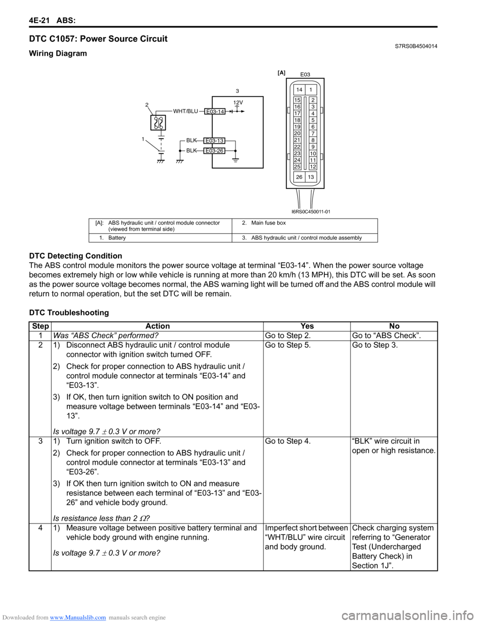
Wiring Diagram
DTC Detecting Condition
The ABS control module monitors the power source voltage at terminal “E03-14”. When the power source voltage
becomes extremely high or low while vehicle is running at more than 20 km/h (13 MPH), this DTC will be set. As soon
as the power source volta ge becomes normal, the ABS warning light will be turned off and the ABS control module will
return to normal operation, bu t the set DTC will be remain.
DTC Troubleshooting
[A]: ABS hydraulic unit / control module connector (viewed from terminal side) 2. Main fuse box
1. Battery 3. ABS hydraulic unit / control module assembly
E03-14WHT/BLU
1 2
3
BLK
BLK
E03-13
E03-26
[A]
E03
15
16
17
18
19
20
21
22
23
24
25 2
3
4
5
6
7
8
9
10
11
12
1
13
14
26
12V
I6RS0C450011-01
Step
Action YesNo
1 Was “ABS Check” performed? Go to Step 2.Go to “ABS Check”.
2 1) Disconnect ABS hydraulic unit / control module connector with ignition switch turned OFF.
2) Check for proper connection to ABS hydraulic unit / control module connector at terminals “E03-14” and
“E03-13”.
3) If OK, then turn ignition switch to ON position and measure voltage between terminals “E03-14” and “E03-
13”.
Is voltage 9.7
± 0.3 V or more? Go to Step 5. Go to Step 3.
3 1) Turn ignition switch to OFF. 2) Check for proper connection to ABS hydraulic unit / control module connector at terminals “E03-13” and
“E03-26”.
3) If OK then turn ignition switch to ON and measure resistance between each terminal of “E03-13” and “E03-
26” and vehicle body ground.
Is resistance less than 2
Ω? Go to Step 4. “BLK” wire circuit in
open or high resistance.
4 1) Measure voltage between positive battery terminal and vehicle body ground with engine running.
Is voltage 9.7
± 0.3 V or more? Imperfect short between
“WHT/BLU” wire circuit
and body ground.
Check charging system
referring to “Generator
Test (Undercharged
Battery Check) in
Section 1J”.
Page 561 of 1496

Downloaded from www.Manualslib.com manuals search engine ABS: 4E-22
DTC C1061: ABS Pump Motor and/or Motor Driver CircuitS7RS0B4504015
Wiring Diagram
DTC Detecting Condition
The ABS control module monitors the voltage at monitor terminal of pump motor circuit constantly with the ignition
switch turned ON. It sets this DTC when the voltage at the monitor terminal does not become high / low according to
ON/OFF commands to the motor driver (transistor) of the module (does not follow these commands).
DTC Troubleshooting 5 1) Measure voltage between terminals “E03-14” and “E03-
13” with engine running.
Is voltage 18
± 1.0 V or less? Poor connection of
“E03-14” and/or “E03-
13” terminals. If the
terminals are in good
condition, substitute a
known-good ABS
hydraulic unit / control
module and recheck.Check charging system
referring to “Generator
Test (Overcharged
Battery Check) in
Section 1J”.
Step Action Yes No
WHT/RED
1 2
5
BLK
BLK
E03-13
E03-26
[A]
E03
15
16
17
18
19
20
21
22
23
24
25 2
3
4
5
6
7
8
9
10
11
12
1
13
14
26
M
3
4E03-1
12V
12V
I6RS0C450012-01
[A]: ABS hydraulic unit / control module connector (viewed from terminal side) 2. Main fuse box 4. ABS pump motor
1. Battery 3. Pump motor driver (transistor) 5. ABS hydraulic unit / control module assembly
StepAction YesNo
1 Was “ABS Check” performed? Go to Step 2.Go to “ABS Check”.
2 1) Turn Ignition switch to OFF position.
2) Disconnect ABS hydraulic unit / control module connector.
3) Check for proper connection to ABS hydraulic unit / control module connector at terminal “E03-1”.
4) If OK, then measure voltage between terminal “E03-1” of module connector and body ground.
Is it 10 – 14 V? Go to Step 3.
“WHT/RED” circuit
open.
3 Measure resistance between terminal “E03-13” and “E03- 26” of ABS hydraulic unit / co ntrol module connector and
body ground.
Is resistance less than 1
Ω? Substitute a known-
good ABS hydraulic unit
/ control module
assembly and recheck.
Ground circuit for ABS
hydraulic unit / control
module open or high
resistance.
Page 562 of 1496
Downloaded from www.Manualslib.com manuals search engine 4E-23 ABS:
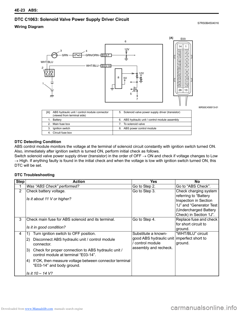
DTC C1063: Solenoid Valve Power Supply Driver CircuitS7RS0B4504016
Wiring Diagram
DTC Detecting Condition
ABS control module monitors the voltage at the terminal of solenoid circuit constantly with ignition switch turned ON.
Also, immediately after ignition switch is turned ON, perform initial check as follows.
Switch solenoid valve power supply driv er (transistor) in the order of OFF → ON and check if voltage changes to Low
→ High. If anything faulty is found in the initial check and when the voltage is low with ignition switch turned ON, this
DTC will be set.
DTC Troubleshooting
[A] E03
15
16
17
18
19
20
21
22
23
24
25 2
3
4
5
6
7
8
9
10
11
12
1
13
14
266
WHT/BLU
12V
5E03-14
5V
12V
8
GRN/ORNE03-7
WHT/BLU
GRN
1
2 3
4
7
I6RS0C450013-01
[A]: ABS hydraulic unit / control module connector
(viewed from terminal side) 5. Solenoid valve power supp
ly driver (transistor)
1. Battery 6. ABS hydraulic unit / control module assembly
2. Main fuse box 7. To solenoid valve
3. Ignition switch 8. ABS power control module
4. Circuit fuse box
Step Action YesNo
1 Was “ABS Check” performed? Go to Step 2.Go to “ABS Check”.
2 Check battery voltage.
Is it about 11 V or higher? Go to Step 3.
Check charging system
referring to “Battery
Inspection in Section
1J” and “Generator Test
(Undercharged Battery
Check) in Section 1J”.
3 Check main fuse for ABS solenoid and its terminal.
Is it in good condition? Go to Step 4.
Replace fuse and check
for short circuit to
ground.
4 1) Turn ignition switch to OFF position.
2) Disconnect ABS hydraulic unit / control module connector.
3) Check for proper connection to ABS hydraulic unit / control module at terminal “E03-14”.
4) If OK, then measure voltage between connector terminal “E03-14” and body ground.
Is it 10 – 14 V? Substitute a known-
good ABS hydraulic unit
/ control module
assembly and recheck.
“WHT/BLU” circuit
imperfect short to
ground.
Page 615 of 1496
Downloaded from www.Manualslib.com manuals search engine Electronic Stability Program: 4F-41
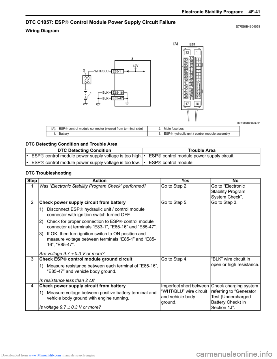
DTC C1057: ESP® Control Module Power Supply Circuit FailureS7RS0B4604053
Wiring Diagram
DTC Detecting Condition and Trouble Area
DTC Troubleshooting
[A]
E85
161
15
2
3
4
5
6
7
8
9
10
11
12
13
14
17
18
19
20
21
22
23
24
25
26
27
28
29
30
31
3233
34
35
36
37
38
39
40
41
42
43
44
45
46
47
WHT/BLU
1
2
3
12V
E85-1
BLKE85-16
E85-47BLK
I6RS0B460023-02
[A]: ESP
® control module connector (viewed from terminal side) 2. Main fuse box
1. Battery 3. ESP ® hydraulic unit / control module assembly
DTC Detecting Condition Trouble Area
• ESP ® control module power supply voltage is too high.
• ESP ® control module power supply voltage is too low. • ESP
® control module power supply circuit
• ESP ® control module
Step Action YesNo
1 Was “Electronic Stability Pr ogram Check” performed? Go to Step 2.Go to “Electronic
Stability Program
System Check”.
2 Check power supply circuit from battery
1) Disconnect ESP ® hydraulic unit / control module
connector with ignition switch turned OFF.
2) Check for proper connection to ESP ® control module
connector at terminals “E83-1”, “E85-16” and “E85-47”.
3) If OK, then turn ignition switch to ON position and measure voltage between terminals “E85-1” and “E85-
16”, “E85-47”.
Are voltage 9.7
± 0.3 V or more? Go to Step 5. Go to Step 3.
3 Check ESP ® control module ground circuit
1) Measure resistance between each terminal of “E85-16”, “E85-47” and vehicle body ground.
Is resistance less than 2
Ω? Go to Step 4. “BLK” wire circuit in
open or high resistance.
4 Check power supply circuit from battery
1) Measure voltage between positive battery terminal and
vehicle body ground with engine running.
Is voltage 9.7
± 0.3 V or more? Imperfect short between
“WHT/BLU” wire circuit
and vehicle body
ground.
Check charging system
referring to “Generator
Test (Undercharged
Battery Check) in
Section 1J”.
Page 616 of 1496
Downloaded from www.Manualslib.com manuals search engine 4F-42 Electronic Stability Program:
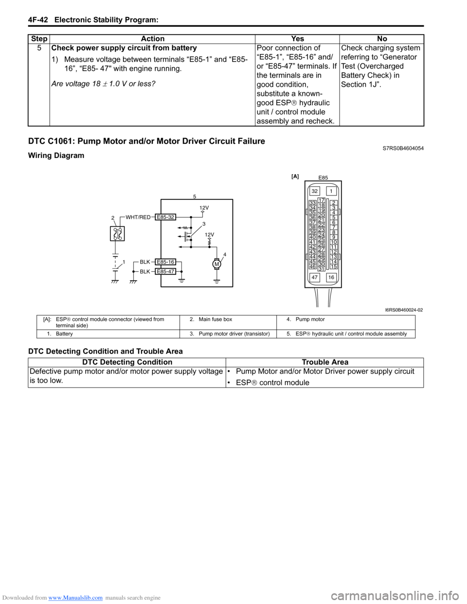
DTC C1061: Pump Motor and/or Motor Driver Circuit FailureS7RS0B4604054
Wiring Diagram
DTC Detecting Condition and Trouble Area5
Check power supply circuit from battery
1) Measure voltage between terminals “E85-1” and “E85-
16”, “E85- 47" with engine running.
Are voltage 18
± 1.0 V or less? Poor connection of
“E85-1”, “E85-16” and/
or “E85-47” terminals. If
the terminals are in
good condition,
substitute a known-
good ESP
® hydraulic
unit / control module
assembly and recheck. Check charging system
referring to “Generator
Test (Overcharged
Battery Check) in
Section 1J”.
Step Action Yes No
[A]
E85
161
15
2
3
4
5
6
7
8
9
10
11
12
13
14
17
18
19
20
21
22
23
24
25
26
27
28
29
30
31
3233
34
35
36
37
38
39
40
41
42
43
44
45
46
47
4
51
2
WHT/RED3
12V
M
12V
BLK
BLK
E85-16
E85-47
E85-32
I6RS0B460024-02
[A]: ESP
® control module connector (viewed from
terminal side) 2. Main fuse box 4. Pump motor
1. Battery 3. Pump motor driver (transistor) 5. ESP® hydraulic unit / control module assembly
DTC Detecting ConditionTrouble Area
Defective pump motor and/or motor power supply voltage
is too low. • Pump Motor and/or Motor Driver power supply circuit
• ESP
® control module