Page 768 of 1496

Downloaded from www.Manualslib.com manuals search engine 5A-124 Automatic Transmission/Transaxle:
Direct Clutch Assembly ComponentsS7RS0B5106037
Direct Clutch Assembly Preliminary CheckS7RS0B5106038
Install direct clutch assembly (1) to oil pump assembly
(2) blow in air (400 – 800 kPa, 4 – 8 kg/cm2, 57 – 113
psi) through oil hole (3) of oil pump assembly with
special tool attached on uppe r surface of direct clutch
piston, and measure piston stroke of direct clutch.
If piston stroke exceeds sp ecified value, disassemble,
inspect and replace inner parts.
Special tool
(A): 09900–20607
(B): 09900–20701
Direct clutch piston stroke
0.4 – 0.7 mm (0.016 – 0.027 in.)
I2RH0B510160-01
1. Input shaft front thrust bearing 6. Outer O-ring 11. Direct clutch retaining plate
2. Input shaft seal ring 7. Direct clutch return spring subassembly 12. Plate snap ring
3. Input shaft subassembly 8. Shaft snap ring : Apply automatic transaxle fluid.
4. Inner O-ring 9. Direct clutch separator plate : Do not reuse.
5. Direct clutch piston 10. Direct clutch disc
I2RH0B510161-01
Page 769 of 1496

Downloaded from www.Manualslib.com manuals search engine Automatic Transmission/Transaxle: 5A-125
Direct Clutch Assembly Disassembly and
Reassembly
S7RS0B5106039
Disassembly1) Remove plate snap ring (1) then remove direct clutch retaining plate, discs and separator plates.
2) Using special tool and hydraulic press, remove shaft snap ring (1).
Special tool
(A): 09926–98310
CAUTION!
Do not press direct clutch return spring
subassembly in over 0.7 mm (0.027 in.).
Excessive compression may cause damage
to direct clutch return spring subassembly
and/or piston.
3) Remove direct clutch re turn spring assembly (2).
4) Using a finger to block oil hole (1), apply compressed air (400 – 800 kPa, 4 – 8 kg/cm
2, 57 –
113 psi) to opposite hole, which will assist in removal
of the clutch piston. 5) Remove outer O-ring (1).
6) Remove inner O-ring (2).
7) Remove input shaft seal rings (1).
I2RH0B510162-01
I2RH0B510163-01
I2RH0B510164-01
2. Direct clutch piston
1. Input shaft subassembly
I2RH0B510165-01
I2RH0B510166-01
I2RH0B510167-01
Page 770 of 1496

Downloaded from www.Manualslib.com manuals search engine 5A-126 Automatic Transmission/Transaxle:
Reassembly
Reverse disassembly procedure for assembly, noting the
following points.
• Use new seal ring and O-ring. Apply A/T fluid before installation.
• Do not damage direct clutch return spring subassembly (1) and piston by pressing in direct
clutch return spring subassembly passing through its
original installing position over 0.7 mm (0.027 in.).
Special tool
(A): 09926–98310
• Apply A/T fluid to direct cl utch separator plates (4),
discs (3) and retaining plate (2).
• Install direct clutch separator plates (4), discs (3), retaining plate (2) and snap ring (1) to input shaft
subassembly.
• Install plate snap ring so that its both ends would be positioned in correct locations as shown in figure. • After assembly, measure direct clutch piston stroke.
Special tool
(A): 09900–20607
(B): 09900–20701
Direct clutch piston stroke
0.4 – 0.7 mm (0.016 – 0.027 in.)
When piston stroke is out of specification, select direct
clutch retaining plate with suitable thickness from
among the following table and replace it.
Available direct clutch retaining plate thickness
I2RH0B510168-01
I2RH0B510169-01
[A]: Correct [B]: Incorrect
ThicknessIdentification mark
3.0 mm (0.118 in.) 1
3.2 mm (0.126 in.) 2
3.4 mm (0.134 in.) 3
2.8 mm (0.110 in.) 4
1. Direct clutch assembly 3. Oil hole
2. Oil pump assembly
I2RH0B510170-01
I2RH0B510171-01
Page 773 of 1496

Downloaded from www.Manualslib.com manuals search engine Automatic Transmission/Transaxle: 5A-129
Forward and Reverse Clutch Assembly
Preliminary Check
S7RS0B5106042
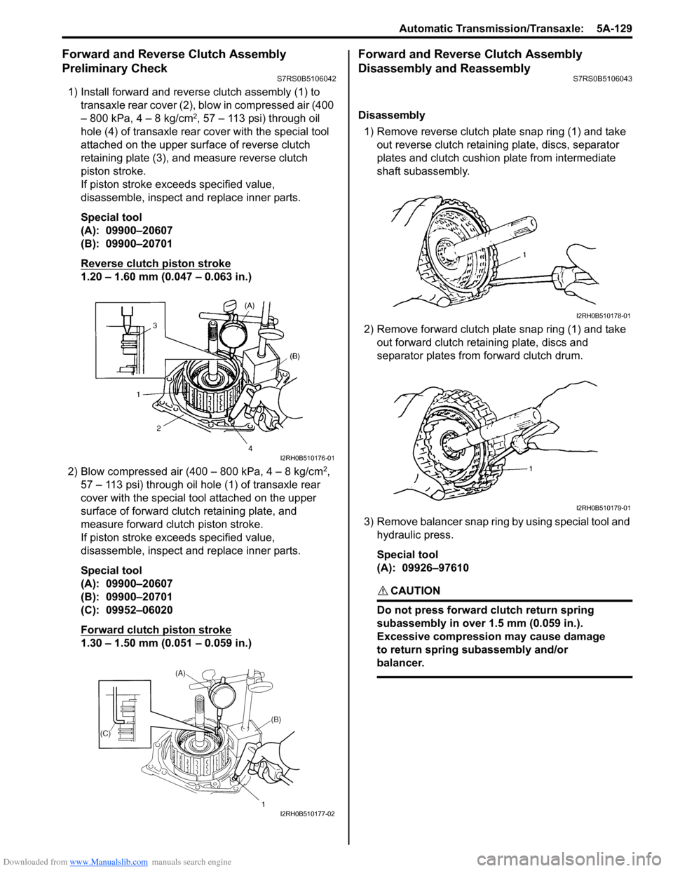
1) Install forward and reverse clutch assembly (1) to
transaxle rear cover (2), blow in compressed air (400
– 800 kPa, 4 – 8 kg/cm
2, 57 – 113 psi) through oil
hole (4) of transaxle rear cover with the special tool
attached on the upper surf ace of reverse clutch
retaining plate (3), and measure reverse clutch
piston stroke.
If piston stroke exce eds specified value,
disassemble, inspect and replace inner parts.
Special tool
(A): 09900–20607
(B): 09900–20701
Reverse clutch piston stroke
1.20 – 1.60 mm (0.047 – 0.063 in.)
2) Blow compressed air (400 – 800 kPa, 4 – 8 kg/cm
2,
57 – 113 psi) through oil hole (1) of transaxle rear
cover with the special tool attached on the upper
surface of forward clutch retaining plate, and
measure forward clutch piston stroke.
If piston stroke exce eds specified value,
disassemble, inspect and replace inner parts.
Special tool
(A): 09900–20607
(B): 09900–20701
(C): 09952–06020
Forward clutch piston stroke
1.30 – 1.50 mm (0.051 – 0.059 in.)
Forward and Reverse Clutch Assembly
Disassembly and Reassembly
S7RS0B5106043
Disassembly
1) Remove reverse clutch plate snap ring (1) and take out reverse clutch retaini ng plate, discs, separator
plates and clutch cushion plate from intermediate
shaft subassembly.
2) Remove forward clutch plate snap ring (1) and take out forward clutch retaining plate, discs and
separator plates from forward clutch drum.
3) Remove balancer snap ring by using special tool and hydraulic press.
Special tool
(A): 09926–97610
CAUTION!
Do not press forward clutch return spring
subassembly in over 1.5 mm (0.059 in.).
Excessive compression may cause damage
to return spring subassembly and/or
balancer.
I2RH0B510176-01
I2RH0B510177-02
I2RH0B510178-01
I2RH0B510179-01
Page 774 of 1496
Downloaded from www.Manualslib.com manuals search engine 5A-130 Automatic Transmission/Transaxle:
4) Remove forward clutch balancer (1).
5) Remove forward clutch return spring subassembly
(1).
6) Install intermed iate shaft subassembly (1) to
transaxle rear cover (2). Apply compressed air (400
– 800 kPa, 4 – 8 kg/cm
2, 57 – 113 psi) to oil hole (3)
of transaxle rear cover to remove forward clutch
piston (4). 7) Apply compressed air (400 – 800 kPa, 4 – 8 kg/cm
2,
57 – 113 psi) to oil hole (1) of transaxle rear cover to
remove forward clutch drum (2).
8) Remove forward clutch piston O-ring (1) from intermediate shaft subassembly (2).
9) Remove forward clutch drum O-ring (1) from forward clutch drum (2).
10) Remove intermediate shaft seal ring (1) from intermediate shaft subassembly (2).
2. Intermediate shaft subassembly
I2RH0B510180-01
I2RH0B510181-01
I2RH0B510182-01
I2RH0B510183-01
I2RH0B510184-01
I2RH0B510185-01
I2RH0B510186-01
Page 776 of 1496

Downloaded from www.Manualslib.com manuals search engine 5A-132 Automatic Transmission/Transaxle:
• Measure forward clutch piston stroke in the same manner as “Forward and Reverse Clutch Assembly
Preliminary Check”.
When piston stroke is out of specification, select
forward clutch retaining plate with proper thickness
from among the following table and replace it.
Special tool
(A): 09900–20607
(B): 09900–20701
(C): 09952–06020
Forward clutch piston stroke
1.30 – 1.50 mm (0.051 – 0.059 in.)
Available forward clutch retaining plate thickness
• Install reverse clutch cushion plate (1) in correct direction as shown in figure.
• Apply A/T fluid to reverse clutch cushion plate (1),
reverse clutch separator plate (2), discs (3) and
retaining plate (4).
• Install reverse clutch cushio n plate (1), reverse clutch
separator plate (2), discs (3), retaining plate (4) and
then snap ring (5) to inte rmediate shaft subassembly. • Install reverse clutch plate snap ring so that its both
ends would be positioned in correct locations as
shown in figure.
• Measure reverse clutch piston stroke in the same manner as “Forward and Reverse Clutch Assembly
Preliminary Check”.
When piston stroke is out of specification, select
reverse clutch retaining plate with proper thickness
from among the following table and replace it.
Special tool
(A): 09900–20607
(B): 09900–20701
Reverse clutch piston stroke
1.20 – 1.60 mm (0.047 – 0.063 in.)
Available reverse clutch retaining plate thickness
Thickness Identification mark
3.0 mm (0.118 in.) 1
3.1 mm (0.122 in.) 5
3.2 mm (0.126 in.) 2
3.3 mm (0.130 in.) 6
3.4 mm (0.134 in.) 3
3.5 mm (0.138 in.) 7
3.6 mm (0.142 in.) 4
1. Oil hole
I2RH0B510177-02
I3RM0B510062-01
[A]: Correct[B]: Incorrect
ThicknessIdentification mark
3.0 mm (0.118 in.) 1
3.2 mm (0.126 in.) 2
3.4 mm (0.134 in.) 3
3.6 mm (0.142 in.) 4
I2RH0B510190-01
I2RH0B510191-01
Page 778 of 1496
Downloaded from www.Manualslib.com manuals search engine 5A-134 Automatic Transmission/Transaxle:
2nd Brake Piston Assembly ComponentsS7RS0B5106045
2nd Brake Piston Assembly Disassembly and
Reassembly
S7RS0B5106046
Disassembly1) Apply compressed air (400 – 800 kPa, 4 – 8 kg/cm
2,
57 – 113 psi) to oil hole (1) of 2nd brake cylinder (3)
to remove 2nd brake piston (2). 2) Remove inner O-ring (1) and outer O-ring (2).
I2RH0B510196-01
1. 2nd brake cylinder
3. Inner O-ring: Apply automatic transaxle fluid.
2. 2nd brake piston 4. Outer O-ring: Do not reuse.
I2RH0B510197-01
I2RH0B510198-01
Page 780 of 1496

Downloaded from www.Manualslib.com manuals search engine 5A-136 Automatic Transmission/Transaxle:
Transaxle Rear Cover (O/D and 2nd Coast Brake
Piston) Assembly Disassembly and
Reassembly
S7RS0B5106048
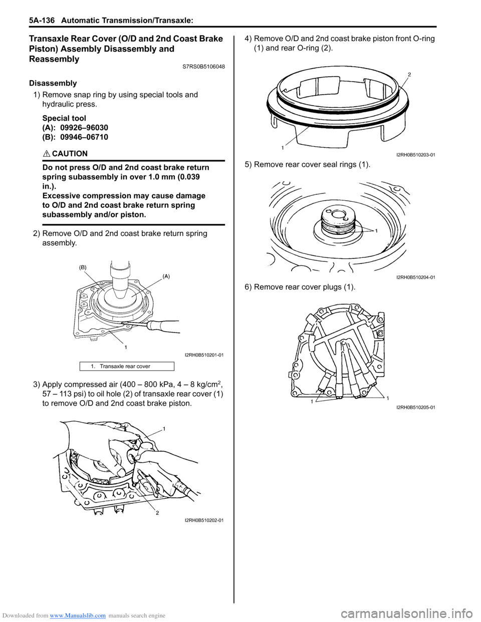
Disassembly1) Remove snap ring by using special tools and hydraulic press.
Special tool
(A): 09926–96030
(B): 09946–06710
CAUTION!
Do not press O/D and 2nd coast brake return
spring subassembly in over 1.0 mm (0.039
in.).
Excessive compression may cause damage
to O/D and 2nd coast brake return spring
subassembly and/or piston.
2) Remove O/D and 2nd coast brake return spring assembly.
3) Apply compressed air (400 – 800 kPa, 4 – 8 kg/cm
2,
57 – 113 psi) to oil hole (2) of transaxle rear cover (1)
to remove O/D and 2nd coast brake piston. 4) Remove O/D and 2nd coast brake piston front O-ring
(1) and rear O-ring (2).
5) Remove rear cove r seal rings (1).
6) Remove rear cover plugs (1).
1. Transaxle rear cover
I2RH0B510201-01
I2RH0B510202-01
I2RH0B510203-01
I2RH0B510204-01
I2RH0B510205-01