2008 SUZUKI SWIFT Ground
[x] Cancel search: GroundPage 566 of 1496

Downloaded from www.Manualslib.com manuals search engine 4E-27 ABS:
DTC U1100: Lost Communication with ECM (Reception Error)S7RS0B4504019
Wiring Diagram
Refer to “DTC U1073: Control Module Communication Bus Off”.
DTC Detecting Condition
Reception error of communication data for ECM is detected more than specified time continuously.
DTC Troubleshooting Step Action Yes No 1 Was “ABS Check” performed? Go to Step 2. Go to “ABS Check”.
2 1) Check DTC for ABS.
Is DTC U1073 detected? Go to “DTC U1073:
Control Module
Communication Bus
Off”.Go to Step 3.
3 1) Check DTC for ECM. Is DTC P1674 detected? Go to “DTC P1674:
CAN Communication
(Bus Off Error) in
Section 1A”.Go to Step 4.
4 1) Check connection of connectors of all control modules communicating by means of CAN.
2) Check DTC for ABS.
Is DTC U1100 detected? Go to Step 5. Intermittent trouble.
Check for intermittent
referring to “Intermittent
and Poor Connection
Inspection in Section
00” in related manual.
5 1) Turn ignition switch to OFF position.
2) Disconnect connectors of ABS control module and ECM
communicating by means of CAN.
3) Check CAN communication circuit between ABS control module and ECM for open, short and high resistance.
Is CAN communication circuit in good condition? Go to Step 6. Repair or replace the
CAN communication
line.
6 1) Disconnect connectors of all control modules communicating by means of CAN.
2) Check CAN communication circuit between control modules other than Step 5 for open, short and high
resistance.
Is each CAn communication circuit in good condition? Go to Step 7. Repair or replace the
CAN communication
line.
7 1) Turn ignition switch to OFF position. 2) Connect connector of disconnected control modules communicating by means of CAN.
3) Disconnect connector from any one of control modules other than BCM and ABS control module.
4) Recheck ABS contro l module for DTC
IS DTC U1100 detected? Disconnected
connectors of control
modules other than the
one whose connector is
disconnected in Step 3)
one by one and check
that DTC U1100 is
detected by ABS control
module each time
connector is
disconnected.
When DTC U1100 is not
detected by ABS
module while checking
in this way, go to
description under “NO”
below. If DTC U1100 is
detected by ABS control
module, go to Step 8.Check power and
ground circuit of control
module disconnected in
Step 3) circuit is OK,
substitute a know-good
control module
disconnected in Step 3)
and recheck.
Page 584 of 1496
Downloaded from www.Manualslib.com manuals search engine 4F-10 Electronic Stability Program:
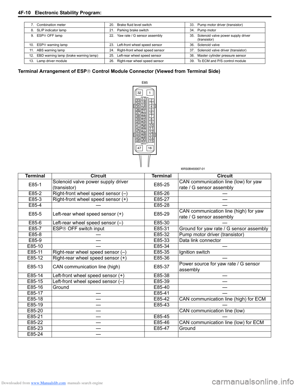
Terminal Arrangement of ESP® Control Module Connector (Viewed from Terminal Side)
7. Combination meter 20. Brake fluid level switch 33. Pump motor driver (transistor)
8. SLIP indicator lamp 21. Parking brake switch 34. Pump motor
9. ESP ® OFF lamp 22. Yaw rate / G sensor assembly 35. Solenoid valve power supply driver
(transistor)
10. ESP ® warning lamp 23. Left-front wheel speed sensor 36. Solenoid valve
11. ABS warning lamp 24. Right-front wheel speed sensor37. Solenoid valve driver (transistor)
12. EBD warning lamp (brake warning lamp) 25. Left-rear wheel speed sensor 38. Master cylinder pressure sensor
13. Lamp driver module 26. Right-rear wheel speed sensor 39. To ECM and P/S control module
Terminal CircuitTerminal Circuit
E85-1 Solenoid valve power supply driver
(transistor) E85-25CAN communication line (low) for yaw
rate / G sensor assembly
E85-2 Right-front wheel speed sensor (–) E85-26—
E85-3 Right-front wheel speed sensor (+) E85-27—
E85-4 —E85-28 —
E85-5 Left-rear wheel speed sensor (+) E85-29CAN communication line (high) for yaw
rate / G sensor assembly
E85-6 Left-rear wheel speed sensor (–) E85-30—
E85-7 ESP® OFF switch input E85-31 Ground for yaw rate / G sensor assembly
E85-8 —E85-32 Pump motor driver (transistor)
E85-9 —E85-33 Data link connector
E85-10 —E85-34 —
E85-11 Right-rear wheel speed sensor (–) E85-35 Ignition switch
E85-12 Right-rear wheel speed sensor (+) E85-36—
E85-13 CAN communication line (high) E85-37Power source for ya
w rate / G sensor
assembly
E85-14 Left-front wheel speed sensor (+) E85-38—
E85-15 Left-front wheel speed sensor (–) E85-39—
E85-16 Ground E85-40—
E85-17 —E85-41 —
E85-18 —E85-42 CAN communication line (high) for ECM
E85-19 —E85-43 —
E85-20 — CAN communication line (low)
E85-21 —E85-45 —
E85-22 —E85-46 CAN communication line (low) for ECM
E85-23 —E85-47 Ground
E85-24 —
E85
161
15
2
3
4
5
6
7
8
9
10
11
12
13
14
17
18
19
20
21
22
23
24
25
26
27
28
29
30
31
3233
34
35
36
37
38
39
40
41
42
43
44
45
46
47
I6RS0B460007-01
Page 590 of 1496

Downloaded from www.Manualslib.com manuals search engine 4F-16 Electronic Stability Program:
�) C1022 Right-front wheel speed
sensor or encoder failure Abnormal wheel speed sensor
signal is detected.
�{
*1 �{
�) C1023 Yaw rate sensor failure • Yaw rate sensor signal is out of
range.
• Vehicle behavior and yaw rate signal is disagreed. ——
�{
�) C1024 Steering angle sensor circuit
failure • Steering angle sensor internal
defect is detected by CPU in
steering angle sensor.
• Steering angle sensor signal is out of specified range. ——
�{
�) C1025 Left-front wheel speed
sensor circuit failure Wheel sensor signal is out of
specified range.
�{
*1 �{
�) C1026 Left-front wheel speed
sensor or encoder failure Abnormal wheel speed sensor
signal is detected.
�{
*1 �{
�) C1027 ESP
® OFF switch circuit
failure Mechanical switch failure, failure in
switch wiring is shorted to ground.
———
�) C1028 Master cylinder pressure
sensor circuit failure Input signal voltage from master
cylinder pressure sensor in ESP
®
control module is too high or low. ——
�{
�) C1031 Right-rear wheel speed
sensor circuit failure Wheel sensor signal is out of
specified range.
�{
*1 �{
�) C1032 Right-rear wheel speed
sensor or encoder failure Abnormal wheel speed sensor
signal is detected.
�{
*1 �{
�) C1034 Yaw rate / G sensor
assembly power supply
failure Power supply voltage of yaw rate /
G sensor assembly is too high when
ignition switch OFF.
——�{
Power supply voltage of yaw rate /
G sensor assembly is too low when
ignition switch ON.
�) C1035 Left-rear wheel speed
sensor circuit failure Wheel sensor signal is out of
specified range.
�{
*1 �{
�) C1036 Lef
t-rear wheel speed
sensor or encoder failure Abnormal wheel speed sensor
signal is detected.
�{
*1 �{
�) C1037 Steering angle sensor power
supply failure Power supply voltage to steering
angle sensor is too low.
——
�{
�) C1038 Steering angle sensor detect
rolling counter failure from
ESP
® control module ESP
® control module rolling
counter failure is detected by
steering angle sensor. ——
�{
�) C1039 Yaw rate / G sensor
assembly internal failure Yaw rate / G sensor assembly
internal failure is detected.
——
�{
�) C1040 Stability control system
function failure Stability control is active for more
than specified time
without yaw rate
change. ——
�{
DTC (displayed
on SUZUKI scan tool) Diagnostic Items
Detecting condition (DTC will
beset when detecting) ABS
warning lamp EBD
warning lamp ESP
®
warning lamp
Page 596 of 1496
Downloaded from www.Manualslib.com manuals search engine 4F-22 Electronic Stability Program:
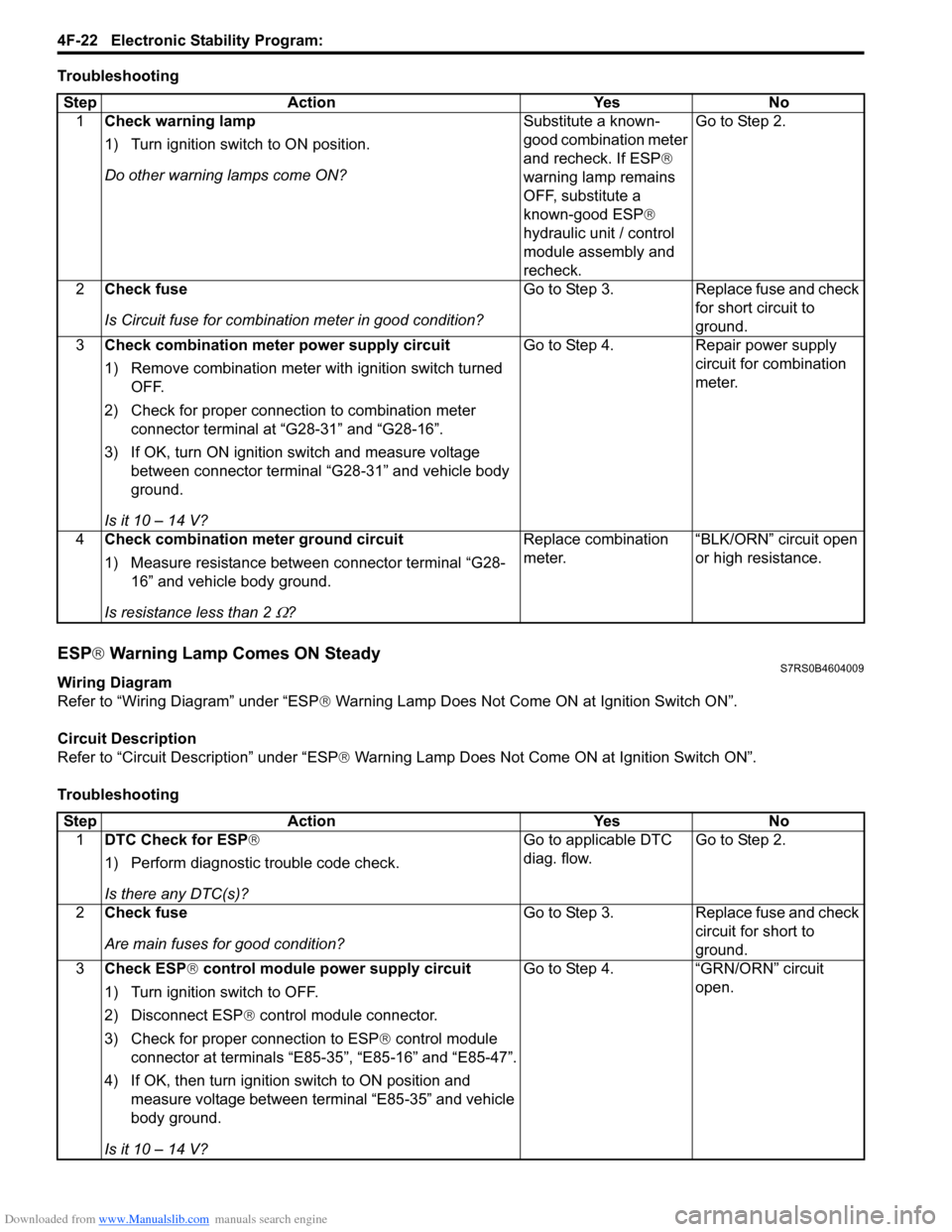
Troubleshooting
ESP® Warning Lamp Comes ON SteadyS7RS0B4604009
Wiring Diagram
Refer to “Wiring Diagram” under “ESP ® Warning Lamp Does Not Come ON at Ignition Switch ON”.
Circuit Description
Refer to “Circuit Description” under “ESP ® Warning Lamp Does Not Come ON at Ignition Switch ON”.
Troubleshooting Step Action Yes No
1 Check warning lamp
1) Turn ignition switch to ON position.
Do other warning lamps come ON? Substitute a known-
good combination meter
and recheck. If ESP®
warning lamp remains
OFF, substitute a
known-good ESP ®
hydraulic unit / control
module assembly and
recheck. Go to Step 2.
2 Check fuse
Is Circuit fuse fo r combination meter in good condition? Go to Step 3. Replace fuse and check
for short circuit to
ground.
3 Check combination meter power supply circuit
1) Remove combination meter wit h ignition switch turned
OFF.
2) Check for proper connection to combination meter connector terminal at “G28-31” and “G28-16”.
3) If OK, turn ON ignition switch and measure voltage between connector terminal “G28-31” and vehicle body
ground.
Is it 10 – 14 V? Go to Step 4. Repair power supply
circuit for combination
meter.
4 Check combination me ter ground circuit
1) Measure resistance between connector terminal “G28- 16” and vehicle body ground.
Is resistance less than 2
Ω? Replace combination
meter.
“BLK/ORN” circuit open
or high resistance.
Step
Action YesNo
1 DTC Check for ESP ®
1) Perform diagnostic trouble code check.
Is there any DTC(s)? Go to applicable DTC
diag. flow.
Go to Step 2.
2 Check fuse
Are main fuses for good condition? Go to Step 3.
Replace fuse and check
circuit for short to
ground.
3 Check ESP ® control module power supply circuit
1) Turn ignition switch to OFF.
2) Disconnect ESP ® control module connector.
3) Check for proper connection to ESP ® control module
connector at terminals “E85-35”, “E85-16” and “E85-47”.
4) If OK, then turn ignition switch to ON position and measure voltage between terminal “E85-35” and vehicle
body ground.
Is it 10 – 14 V? Go to Step 4.
“GRN/ORN” circuit
open.
Page 597 of 1496
Downloaded from www.Manualslib.com manuals search engine Electronic Stability Program: 4F-23
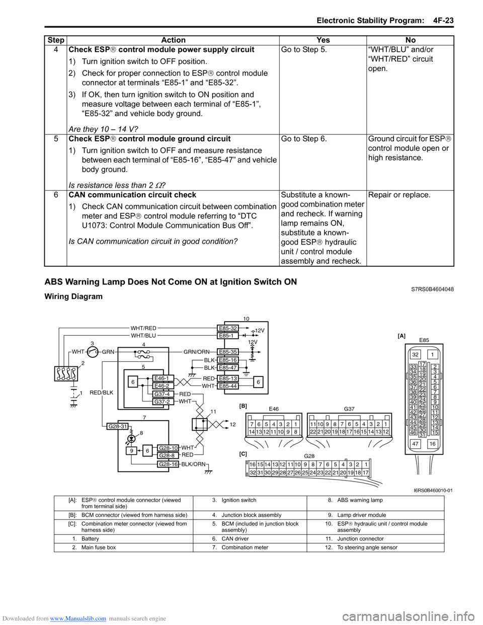
ABS Warning Lamp Does Not Come ON at Ignition Switch ONS7RS0B4604048
Wiring Diagram4
Check ESP ® control module power supply circuit
1) Turn ignition switch to OFF position.
2) Check for proper connection to ESP ® control module
connector at terminals “E85-1” and “E85-32”.
3) If OK, then turn ignition switch to ON position and measure voltage between each terminal of “E85-1”,
“E85-32” and vehicle body ground.
Are they 10 – 14 V? Go to Step 5. “WHT/BLU” and/or
“WHT/RED” circuit
open.
5 Check ESP ® control module ground circuit
1) Turn ignition switch to OFF and measure resistance between each terminal of “E85-16”, “E85-47” and vehicle
body ground.
Is resistance less than 2
Ω? Go to Step 6.
Ground circuit for ESP®
control module open or
high resistance.
6 CAN communication circuit check
1) Check CAN communication circuit between combination
meter and ESP ® control module referring to “DTC
U1073: Control Module Communication Bus Off”.
Is CAN communication circuit in good condition? Substitute a known-
good combination meter
and recheck. If warning
lamp remains ON,
substitute a known-
good ESP
® hydraulic
unit / control module
assembly and recheck. Repair or replace.
Step
Action YesNo
[A]
E85
161
15
2
3
4
5
6
7
8
9
10
11
12
13
14
17
18
19
20
21
22
23
24
25
26
27
28
29
30
31
3233
34
35
36
37
38
39
40
41
42
43
44
45
46
47
WHTGRN
3
E85-13
E85-44REDWHT6 5E46-1E46-2
4 10
6
E85-16
E85-47BLKBLK
8
9
BLK/ORN
REDWHT
REDWHT
G37-4G37-2
G28-10G28-8
G28-16
12V
12VE85-32E85-1
E85-35
WHT/REDWHT/BLU
GRN/ORN
6
2
1
7 1112[B]
G37
E46124
53
67
891011121314124
53
67
891011
1213141516171819202122
[C] G28
12345678910111213141516
17181920212223242526272829303132
G28-31
RED/BLK
I6RS0B460010-01
[A]: ESP ® control module connector (viewed
from terminal side) 3. Ignition switch 8. ABS warning lamp
[B]: BCM connector (viewed from harness side) 4. Junction block assembly 9. Lamp driver module
[C]: Combination meter connector (viewed from harness side) 5. BCM (included in junction block
assembly) 10. ESP
® hydraulic unit / control module
assembly
1. Battery 6. CAN driver11. Junction connector
2. Main fuse box 7. Combination meter12. To steering angle sensor
Page 599 of 1496
Downloaded from www.Manualslib.com manuals search engine Electronic Stability Program: 4F-25
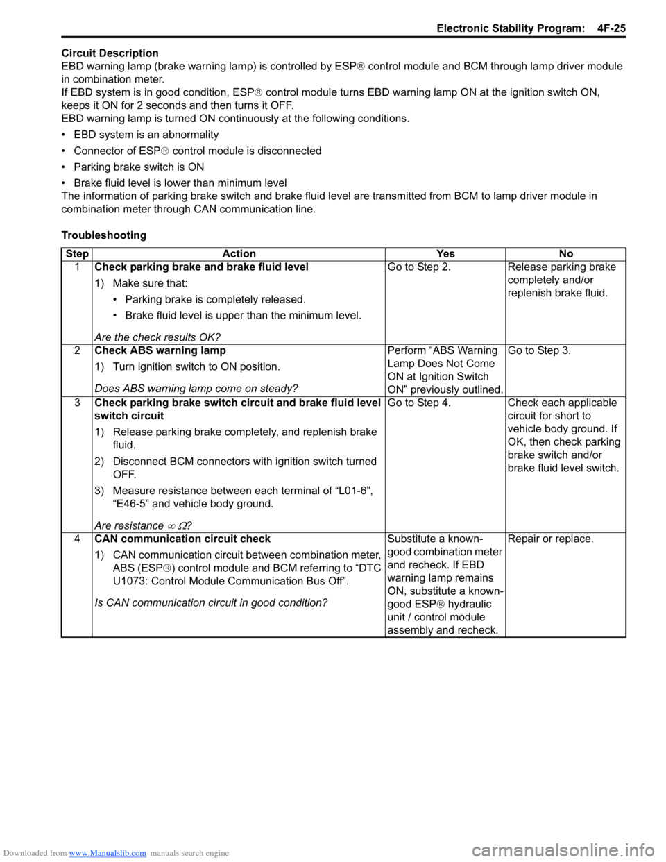
Circuit Description
EBD warning lamp (brake warning lamp) is controlled by ESP® control module and BCM through lamp driver module
in combination meter.
If EBD system is in good condition, ESP ® control module turns EBD warning lamp ON at the ignition switch ON,
keeps it ON for 2 seconds and then turns it OFF.
EBD warning lamp is turned ON cont inuously at the following conditions.
• EBD system is an abnormality
• Connector of ESP ® control module is disconnected
• Parking brake switch is ON
• Brake fluid level is lower than minimum level
The information of parking brake switch and brake fluid leve l are transmitted from BCM to lamp driver module in
combination meter through CAN communication line.
Troubleshooting
Step Action Yes No 1 Check parking brake and brake fluid level
1) Make sure that:
• Parking brake is completely released.
• Brake fluid level is upper than the minimum level.
Are the check results OK? Go to Step 2. Release parking brake
completely and/or
replenish brake fluid.
2 Check ABS warning lamp
1) Turn ignition switch to ON position.
Does ABS warning lamp come on steady? Perform “ABS Warning
Lamp Does Not Come
ON at Ignition Switch
ON” previously outlined.Go to Step 3.
3 Check parking brake switch circuit and brake fluid level
switch circuit
1) Release parking brake completely, and replenish brake
fluid.
2) Disconnect BCM connectors with ignition switch turned OFF.
3) Measure resistance between each terminal of “L01-6”, “E46-5” and vehicle body ground.
Are resistance
∞ Ω? Go to Step 4. Check each applicable
circuit for short to
vehicle body ground. If
OK, then check parking
brake switch and/or
brake fluid level switch.
4 CAN communication circuit check
1) CAN communication circuit between combination meter,
ABS (ESP® ) control module and BCM referring to “DTC
U1073: Control Module Communication Bus Off”.
Is CAN communication circuit in good condition? Substitute a known-
good combination meter
and recheck. If EBD
warning lamp remains
ON, substitute a known-
good ESP
® hydraulic
unit / control module
assembly and recheck. Repair or replace.
Page 600 of 1496
![SUZUKI SWIFT 2008 2.G Service Workshop Manual Downloaded from www.Manualslib.com manuals search engine 4F-26 Electronic Stability Program:
Serial Data Link Circuit CheckS7RS0B4604012
Wiring Diagram
Inspection
[A]E85
161
15
2
3
4
5
6
7
8
9
10
11
SUZUKI SWIFT 2008 2.G Service Workshop Manual Downloaded from www.Manualslib.com manuals search engine 4F-26 Electronic Stability Program:
Serial Data Link Circuit CheckS7RS0B4604012
Wiring Diagram
Inspection
[A]E85
161
15
2
3
4
5
6
7
8
9
10
11](/manual-img/20/7607/w960_7607-599.png)
Downloaded from www.Manualslib.com manuals search engine 4F-26 Electronic Stability Program:
Serial Data Link Circuit CheckS7RS0B4604012
Wiring Diagram
Inspection
[A]E85
161
15
2
3
4
5
6
7
8
9
10
11
12
13
14
17
18
19
20
21
22
23
24
25
26
27
28
29
30
31
3233
34
35
36
37
38
39
40
41
42
43
44
45
46
47WHTGRN
3
E85-13REDWHT6 5E46-1E46-2
4
10
6
E85-16
E85-47BLKBLK
8
9
BLK/ORN
REDWHT
REDWHT
G37-4G37-2
G28-10G28-8
G28-16
G28-31
12V
12VE85-32E85-1
E85-35
WHT/REDWHT/BLU
GRN/ORN
6
2
1
7 1415 [B]
G37
E46
124
53
67
891011121314124
53
67
891011
1213141516171819202122
[C] G28
12345678910111213141516
17181920212223242526272829303132
12V
11
PPL/WHT
PPL/WHT
E85-33
E85-44
12
13
WHTWHT/REDB
G G1
RED/BLK
I6RS0B460012-01
[A]: ESP
® control module connector (viewed
from terminal side) 4. Junction block assembly 10. ESP
® hydraulic unit / control module assembly
[B]: BCM connector (viewed from harness side) 5. BCM (included in junction block
assembly) 11. Data link connector (DLC)
[C]: Combination meter connector (viewed from harness side) 6. CAN driver 12. To SDM
1. Battery 7. Combination meter 13. To ECM and P/S control module
2. Main fuse box 8. ESP ® warning lamp 14. Junction connector
3. Ignition switch 9. Lamp driver module 15. To steering angle sensor
Step Action YesNo
1 Check ESP ® warning lamp
1) Turn ignition switch to ON position.
Does ESP
® warning lamp come ON? Go to Step 2. Go to Step 6.
2 Check fuse
1) Turn ignition switch to OFF position.
Are main fuses for good condition? Go to Step 3. Replace fuse and check
for short.
3 Check ESP ® control module power supply circuit
1) Disconnect ESP ® control module connector.
2) Check for proper connection to ESP ® control module
connector at terminal “E85-35”.
3) If OK, then turn ignition switch to ON position and measure voltage between terminal “E85-35” and vehicle
body ground.
Is it 10 – 14 V? Go to Step 4.
“GRN/ORN” wire circuit
open.
Page 601 of 1496
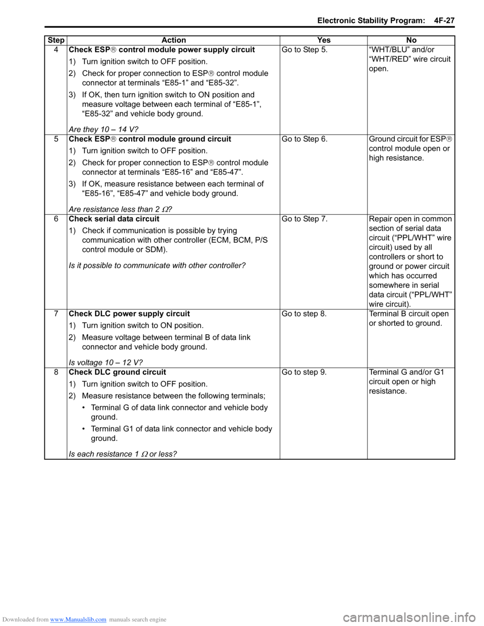
Downloaded from www.Manualslib.com manuals search engine Electronic Stability Program: 4F-27
4Check ESP ® control module power supply circuit
1) Turn ignition switch to OFF position.
2) Check for proper connection to ESP ® control module
connector at terminals “E85-1” and “E85-32”.
3) If OK, then turn ignition switch to ON position and measure voltage between each terminal of “E85-1”,
“E85-32” and vehicle body ground.
Are they 10 – 14 V? Go to Step 5. “WHT/BLU” and/or
“WHT/RED” wire circuit
open.
5 Check ESP ® control module ground circuit
1) Turn ignition switch to OFF position.
2) Check for proper connection to ESP ® control module
connector at terminals “E85-16” and “E85-47”.
3) If OK, measure resistance between each terminal of “E85-16”, “E85-47” and vehicle body ground.
Are resistance less than 2
Ω? Go to Step 6. Ground circuit for ESP
®
control module open or
high resistance.
6 Check serial data circuit
1) Check if communication is possible by trying
communication with other c ontroller (ECM, BCM, P/S
control module or SDM).
Is it possible to commun icate with other controller? Go to Step 7. Repair open in common
section of serial data
circuit (“PPL/WHT” wire
circuit) used by all
controllers or short to
ground or power circuit
which has occurred
somewhere in serial
data circuit (“PPL/WHT”
wire circuit).
7 Check DLC power supply circuit
1) Turn ignition switch to ON position.
2) Measure voltage between terminal B of data link
connector and vehicle body ground.
Is voltage 10 – 12 V? Go to step 8. Terminal B circuit open
or shorted to ground.
8 Check DLC ground circuit
1) Turn ignition switch to OFF position.
2) Measure resistance between the following terminals;
• Terminal G of data link connector and vehicle body ground.
• Terminal G1 of data link connector and vehicle body ground.
Is each resistance 1
Ω or less? Go to step 9. Terminal G and/or G1
circuit open or high
resistance.
Step Action Yes No