2008 SUZUKI SWIFT yellow
[x] Cancel search: yellowPage 826 of 1496
Downloaded from www.Manualslib.com manuals search engine 5B-12 Manual Transmission/Transaxle:
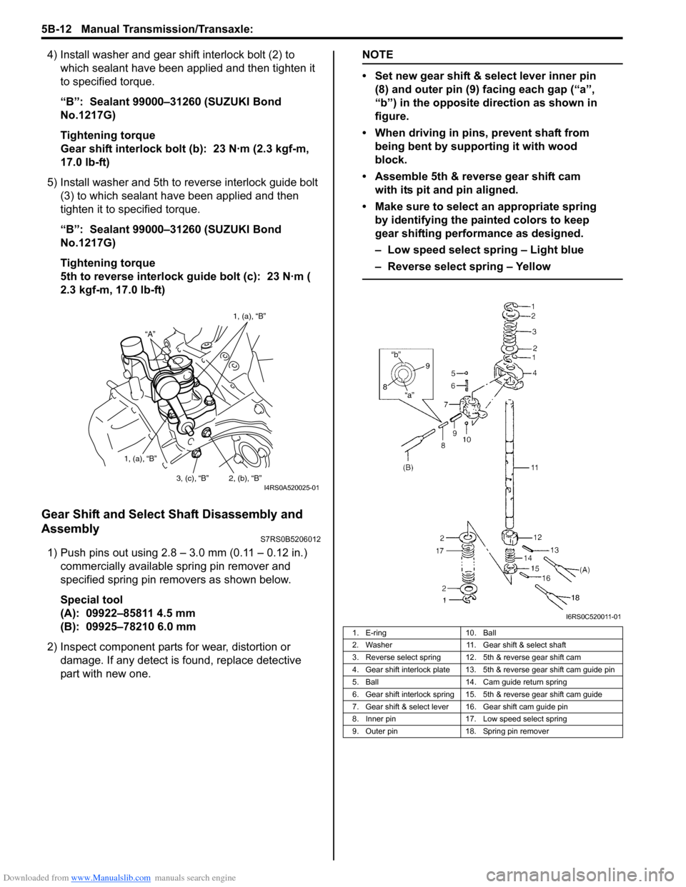
4) Install washer and gear shift interlock bolt (2) to which sealant have been app lied and then tighten it
to specified torque.
“B”: Sealant 99000–31260 (SUZUKI Bond
No.1217G)
Tightening torque
Gear shift interlock bolt (b): 23 N·m (2.3 kgf-m,
17.0 lb-ft)
5) Install washer and 5th to reverse interlock guide bolt (3) to which sealant have been applied and then
tighten it to specified torque.
“B”: Sealant 99000–31260 (SUZUKI Bond
No.1217G)
Tightening torque
5th to reverse interlock guide bolt (c): 23 N·m (
2.3 kgf-m, 17.0 lb-ft)
Gear Shift and Select Shaft Disassembly and
Assembly
S7RS0B5206012
1) Push pins out using 2.8 – 3.0 mm (0.11 – 0.12 in.) commercially available spring pin remover and
specified spring pin removers as shown below.
Special tool
(A): 09922–85811 4.5 mm
(B): 09925–78210 6.0 mm
2) Inspect component parts for wear, distortion or
damage. If any detect is found, replace detective
part with new one.
NOTE
• Set new gear shift & select lever inner pin (8) and outer pin (9) facing each gap (“a”,
“b”) in the opposite direction as shown in
figure.
• When driving in pins, prevent shaft from being bent by supporting it with wood
block.
• Assemble 5th & reverse gear shift cam with its pit and pin aligned.
• Make sure to select an appropriate spring by identifying the painted colors to keep
gear shifting performance as designed.
– Low speed select spring – Light blue
– Reverse select spring – Yellow
“A” 1, (a), “B”
1, (a), “B” 2, (b), “B”
3, (c), “B”
I4RS0A520025-01
1. E-ring 10. Ball
2. Washer 11. Gear shift & select shaft
3. Reverse select spring 12. 5th & reverse gear shift cam
4. Gear shift interlock plate 13. 5th & reverse gear shift cam guide pin
5. Ball 14. Cam guide return spring
6. Gear shift interlock spring 15. 5th & reverse gear shift cam guide
7. Gear shift & select lever 16. Gear shift cam guide pin
8. Inner pin 17. Low speed select spring
9. Outer pin 18. Spring pin remover
I6RS0C520011-01
Page 846 of 1496
Downloaded from www.Manualslib.com manuals search engine 5B-32 Manual Transmission/Transaxle:
5th and Reverse Gear Shift Shafts Disassembly
and Assembly
S7RS0B5206023
Disassembly
Disassemble component parts using special tool and
hammer.
Special tool
(A): 09922–85811
Assembly
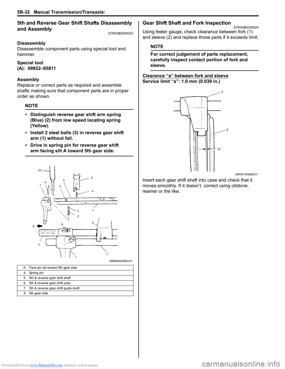
Replace or correct parts as required and assemble
shafts making sure that component parts are in proper
order as shown.
NOTE
• Distinguish reverse gear shift arm spring (Blue) (2) from low speed locating spring
(Yellow).
• Install 2 steel balls (3) in reverse gear shift arm (1) without fail.
• Drive in spring pin for reverse gear shift arm facing slit A toward 5th gear side.
Gear Shift Shaft and Fork InspectionS7RS0B5206024
Using feeler gauge, check clearance between fork (1)
and sleeve (2) and replace those parts if it exceeds limit.
NOTE
For correct judgement of parts replacement,
carefully inspect contact portion of fork and
sleeve.
Clearance “a” between fork and sleeve
Service limit “a”: 1.0 mm (0.039 in.)
Insert each gear shift shaft into case and check that it
moves smoothly. If it doesn’t, correct using oilstone,
reamer or the like.
A: Face pin slit toward 5th gear side
4. Spring pin
5. 5th & reverse gear shift shaft
6. 5th & reverse gear shift yoke
7. 5th & reverse gear shift guide shaft
8. 5th gear side
I3RM0A520053-01
I2RH01520068-01
Page 1034 of 1496
Downloaded from www.Manualslib.com manuals search engine 8A-3 Seat Belts:
Repair Instructions
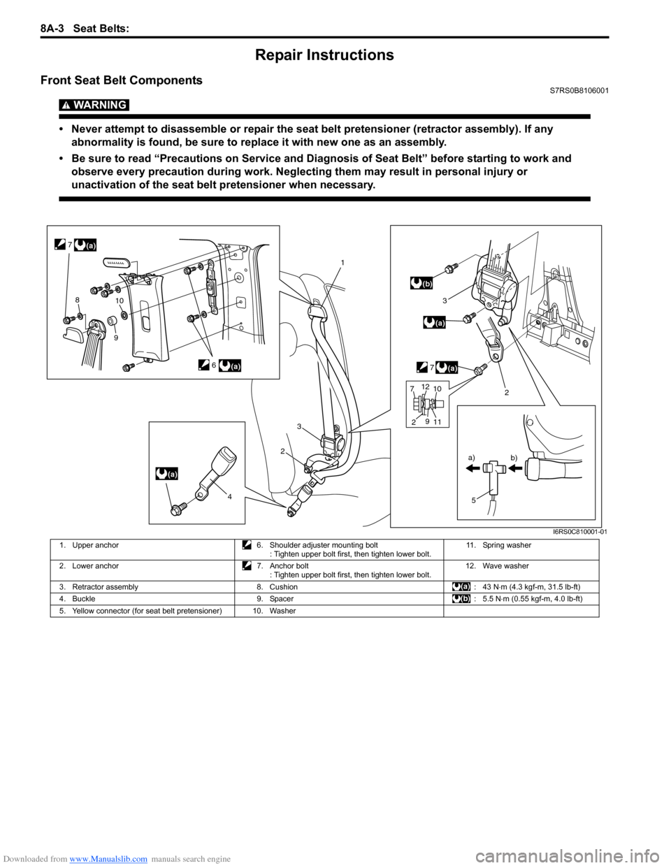
Front Seat Belt ComponentsS7RS0B8106001
WARNING!
• Never attempt to disassemble or repair the seat belt pretensioner (retractor assembly). If any abnormality is found, be sure to replace it with new one as an assembly.
• Be sure to read “Precautions on Service and Diagnosis of Seat Belt” before starting to work and observe every precaution during work. Neglecting them may result in personal injury or
unactivation of the seat belt pretensioner when necessary.
(a)
(a)
(a)
1
2
3
5
a)
b)
(a)
3
7
(b)
6
2
4
(a)
7
810
9
7 2 11
9
1012
I6RS0C810001-01
1. Upper anchor
6. Shoulder adjuster mounting bolt
: Tighten upper bolt first, then tighten lower bolt. 11. Spring washer
2. Lower anchor 7. Anchor bolt
: Tighten upper bolt first, then tighten lower bolt. 12. Wave washer
3. Retractor assembly 8. Cushion : 43 N⋅m (4.3 kgf-m, 31.5 lb-ft)
4. Buckle 9. Spacer : 5.5 N⋅m (0.55 kgf-m, 4.0 lb-ft)
5. Yellow connector (for seat belt pretensioner) 10. Washer
Page 1035 of 1496
Downloaded from www.Manualslib.com manuals search engine Seat Belts: 8A-4
Front Seat Belt Removal and InstallationS7RS0B8106002
WARNING!
• Never attempt to disassemble or repair the seat belt pretensioner (retractor
assembly). If any abnormality is found, be
sure to replace it with new one as an
assembly.
• Be sure to read “Precautions on Service and Diagnosis of Seat Belt” before starting
to work and observe every precaution
during work. Ne glecting them may result in
personal injury or una ctivation of the seat
belt pretensioner when necessary.
Removal
1) Disconnect negative (–) cable at battery.
2) Disable air bag system. Refer to “Disabling Air Bag System in Section 8B”.
3) Remove center pillar lower trim.
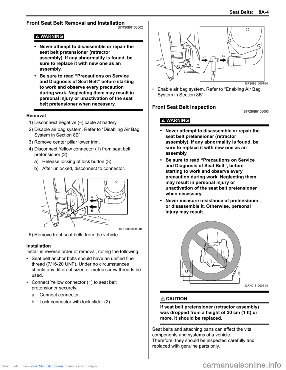
4) Disconnect Yellow connector (1) from seat belt pretensioner (2).
a) Release locking of lock button (3).
b) After unlocked, disconnect to connector.
5) Remove front seat belts from the vehicle.
Installation
Install in reverse order of removal, noting the following.
• Seat belt anchor bolts should have an unified fine thread (7/16-20 UNF). Under no circumstances
should any different sized or metric screw threads be
used.
• Connect Yellow connector (1) to seat belt pretensioner securely.
a. Connect connector.
b. Lock connector with lock slider (2). • Enable air bag system. Refer to “Enabling Air Bag
System in Section 8B”.
Front Seat Belt InspectionS7RS0B8106003
WARNING!
• Never attempt to disassemble or repair the seat belt pretensioner (retractor
assembly). If any abnormality is found, be
sure to replace it with new one as an
assembly.
• Be sure to read “Precautions on Service and Diagnosis of Seat Belt”, before
starting to work and observe every
precaution during work. Neglecting them
may result in personal injury or
unactivation of the seat belt pretensioner
when necessary.
• Never measure resistance of pretensioner or disassemble it. Otherwise, personal
injury may result.
CAUTION!
If seat belt pretensioner (retractor assembly)
was dropped from a height of 30 cm (1 ft) or
more, it should be replaced.
Seat belts and attaching parts can affect the vital
components and systems of a vehicle.
Therefore, they should be inspected carefully and
replaced with genuine parts only.
a
b
21 3I6RS0B810003-01
1
1
2
b)
a)
I6RS0B810004-01
I2RH01810004-01
Page 1042 of 1496
Downloaded from www.Manualslib.com manuals search engine 8B-4 Air Bag System:
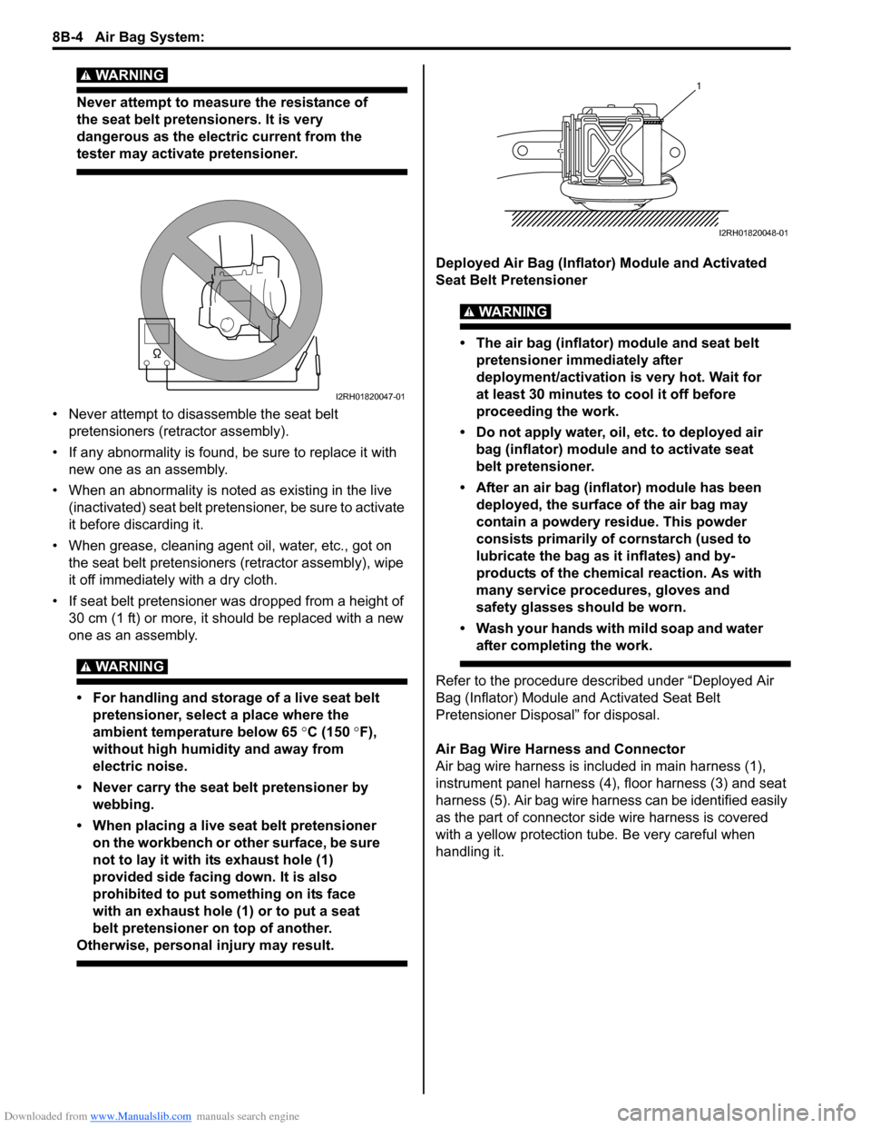
WARNING!
Never attempt to measure the resistance of
the seat belt pretensioners. It is very
dangerous as the electric current from the
tester may activate pretensioner.
• Never attempt to disassemble the seat belt
pretensioners (retractor assembly).
• If any abnormality is found, be sure to replace it with
new one as an assembly.
• When an abnormality is noted as existing in the live (inactivated) seat belt preten sioner, be sure to activate
it before discarding it.
• When grease, cleaning agent oil, water, etc., got on the seat belt pretensioners (r etractor assembly), wipe
it off immediately with a dry cloth.
• If seat belt pretensioner was dropped from a height of 30 cm (1 ft) or more, it should be replaced with a new
one as an assembly.
WARNING!
• For handling and storage of a live seat belt pretensioner, select a place where the
ambient temperature below 65 °C (150 ° F),
without high humidity and away from
electric noise.
• Never carry the seat belt pretensioner by webbing.
• When placing a live seat belt pretensioner on the workbench or other surface, be sure
not to lay it with its exhaust hole (1)
provided side facing down. It is also
prohibited to put something on its face
with an exhaust hole (1) or to put a seat
belt pretensioner on top of another.
Otherwise, personal injury may result.
Deployed Air Bag (Inflator) Module and Activated
Seat Belt Pretensioner
WARNING!
• The air bag (inflator) module and seat belt
pretensioner immediately after
deployment/activation is very hot. Wait for
at least 30 minutes to cool it off before
proceeding the work.
• Do not apply water, oil, etc. to deployed air bag (inflator) module and to activate seat
belt pretensioner.
• After an air bag (inflator) module has been deployed, the surface of the air bag may
contain a powdery residue. This powder
consists primarily of cornstarch (used to
lubricate the bag as it inflates) and by-
products of the chemical reaction. As with
many service procedures, gloves and
safety glasses should be worn.
• Wash your hands with mild soap and water after completing the work.
Refer to the procedure described under “Deployed Air
Bag (Inflator) Module and Activated Seat Belt
Pretensioner Disposal” for disposal.
Air Bag Wire Harness and Connector
Air bag wire harness is includ ed in main harness (1),
instrument panel harness (4), floor harness (3) and seat
harness (5). Air bag wire harness can be identified easily
as the part of connector side wire harness is covered
with a yellow protection tube. Be very careful when
handling it.
I2RH01820047-01
1
I2RH01820048-01
Page 1136 of 1496
Downloaded from www.Manualslib.com manuals search engine 8B-98 Air Bag System:
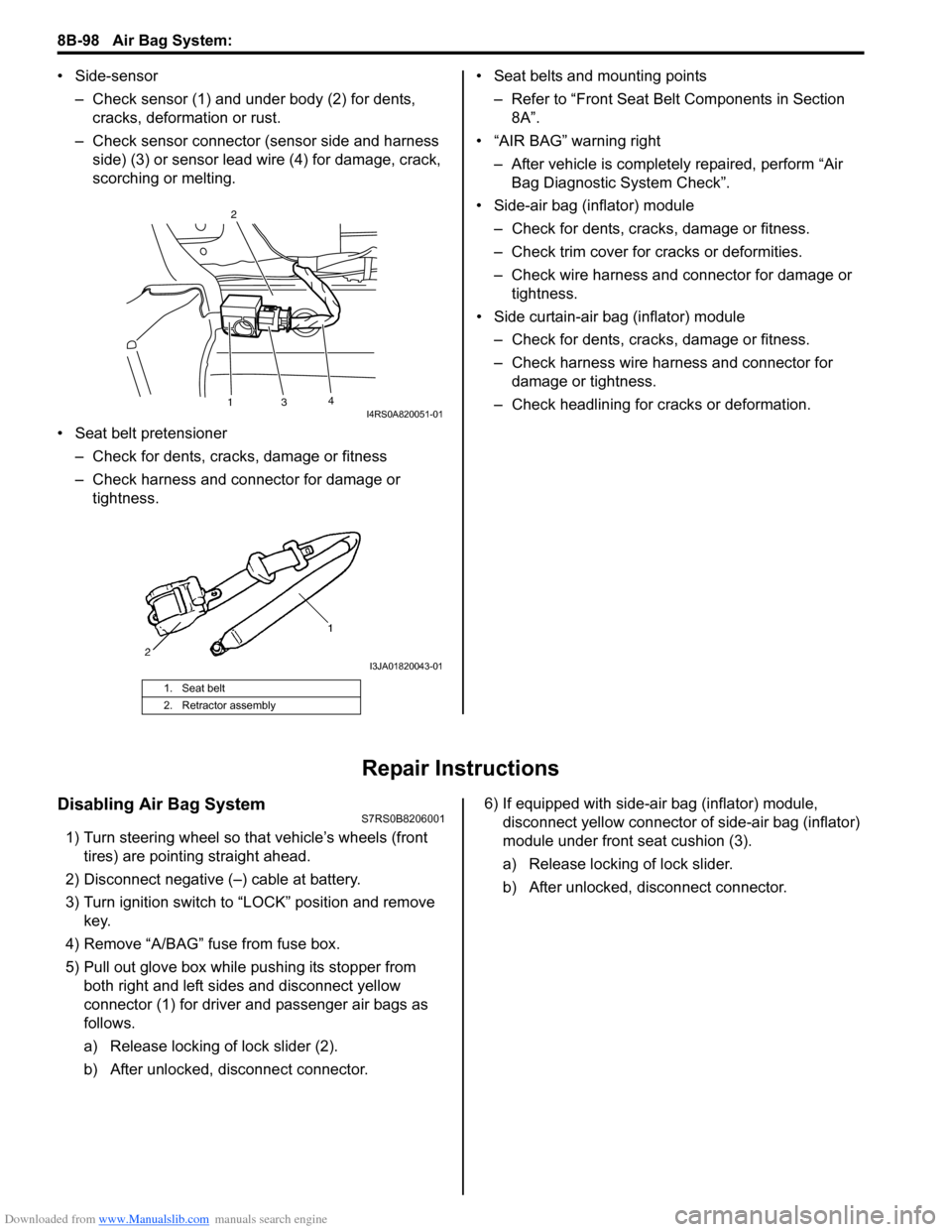
• Side-sensor– Check sensor (1) and under body (2) for dents, cracks, deformation or rust.
– Check sensor connector (sensor side and harness side) (3) or sensor lead wire (4) for damage, crack,
scorching or melting.
• Seat belt pretensioner – Check for dents, cracks , damage or fitness
– Check harness and connector for damage or tightness. • Seat belts and mounting points
– Refer to “Front Seat Belt Components in Section 8A”.
• “AIR BAG” warning right
– After vehicle is completely repaired, perform “Air Bag Diagnostic System Check”.
• Side-air bag (inflator) module – Check for dents, cra cks, damage or fitness.
– Check trim cover for cracks or deformities.
– Check wire harness and connector for damage or tightness.
• Side curtain-air bag (inflator) module – Check for dents, cra cks, damage or fitness.
– Check harness wire harness and connector for damage or tightness.
– Check headlining for cracks or deformation.
Repair Instructions
Disabling Air Bag SystemS7RS0B8206001
1) Turn steering wheel so that vehicle’s wheels (front tires) are pointing straight ahead.
2) Disconnect negative (–) cable at battery.
3) Turn ignition switch to “LOCK” position and remove key.
4) Remove “A/BAG” fu se from fuse box.
5) Pull out glove box while pushing its stopper from
both right and left sides and disconnect yellow
connector (1) for driver and passenger air bags as
follows.
a) Release locking of lock slider (2).
b) After unlocked, disconnect connector. 6) If equipped with side-air bag (inflator) module,
disconnect yellow connector of side-air bag (inflator)
module under front seat cushion (3).
a) Release locking of lock slider.
b) After unlocked, disconnect connector.
1. Seat belt
2. Retractor assembly
13 4
2I4RS0A820051-01
I3JA01820043-01
Page 1137 of 1496
Downloaded from www.Manualslib.com manuals search engine Air Bag System: 8B-99
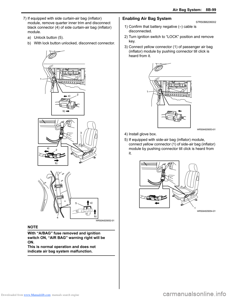
7) If equipped with side curtain-air bag (inflator) module, remove quarter inner trim and disconnect
black connector (4) of side curtain-air bag (inflator)
module.
a) Unlock button (5).
b) With lock button unlocked, disconnect connector.
NOTE
With “A/BAG” fuse removed and ignition
switch ON, “AIR BAG” warning right will be
ON.
This is normal operation and does not
indicate air bag system malfunction.
Enabling Air Bag SystemS7RS0B8206002
1) Confirm that battery negative (–) cable is disconnected.
2) Turn ignition switch to “LOCK” position and remove key.
3) Connect yellow connector (1) of passenger air bag (inflator) module by push ing connector till click is
heard from it.
4) Install glove box.
5) If equipped with side-air bag (inflator) module, connect yellow connector (1) of side-air bag (inflator)
module by pushing connector till click is heard from
it.
a)
b)2
3
2a)
b)
1
5
4 a)
b)
I4RS0A820052-01
1
I4RS0A820053-01
1I4RS0A820054-01