Page 328 of 1496
Downloaded from www.Manualslib.com manuals search engine 1D-43 Engine Mechanical:
Valve Spring InspectionS7RS0B1406028
Valve Spring Free Length and Preload
Referring to data, check to be sure that each spring is in
sound condition, free of any evidence of breakage or
weakening. Remember, weakened valve springs can
cause chatter, not to mention possibility of reducing
power output due to gas leakage caused by decreased
seating pressure.
Valve spring free length
Standard: 39.37 mm (1.550 in.)
Limit: 36.49 mm (1.437 in.)
Valve spring preload
Standard: 161– 185 N (16.1 – 18.5 kg)
(35.4 – 40.7 lb / 1.240 in.)
Limit: 159 N (15.9 kg) for 31.50 mm (35.1 lb / 1.240 in.) Spring Squareness
Use a square and surface plate to check each spring for
squareness in terms of clearance between end of valve
spring and square. Valve springs found to exhibit a
larger clearance than limit must be replaced.
Valve spring squareness
Limit: 1.7 mm (0.067 in.)
I2RH01140143-01
I2RH01140144-01
Page 338 of 1496
Downloaded from www.Manualslib.com manuals search engine 1D-53 Engine Mechanical:
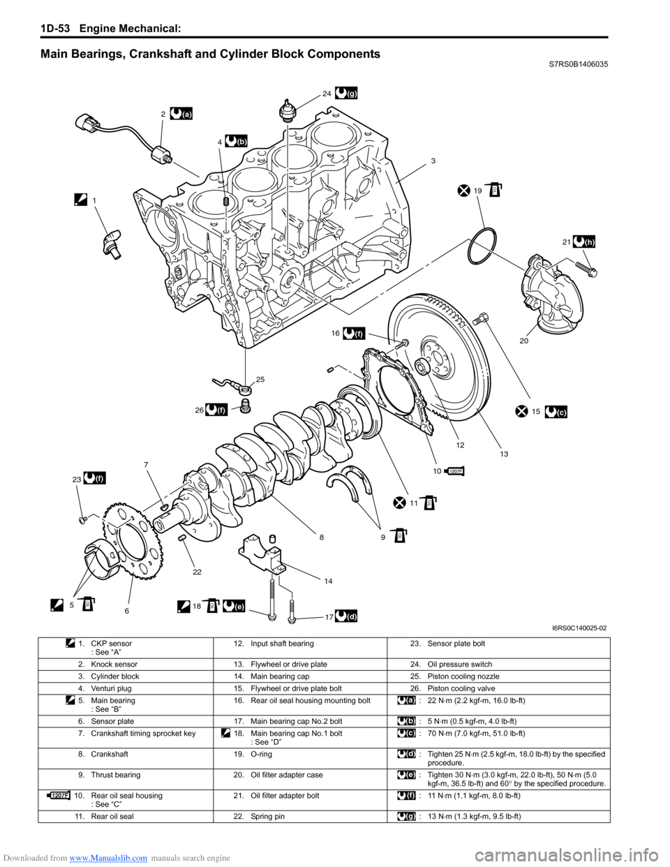
Main Bearings, Crankshaft and Cylinder Block ComponentsS7RS0B1406035
(a)
(c)
(d)(e)
(b)
(f)
(f)
(f)
(g)
(h)
12
3
4
5 67
8910
11 15
12 13
14 16
17
18 19
2021
22
23 24
25
26
OIL
OIL
OIL
OILOIL
I6RS0C140025-02
1. CKP sensor : See “A” 12. Input shaft bearing 23. Sensor plate bolt
2. Knock sensor 13. Flywheel or drive plate 24. Oil pressure switch 3. Cylinder block 14. Main bearing cap 25. Piston cooling nozzle
4. Venturi plug 15. Flywheel or drive plate bolt 26. Piston cooling valve
5. Main bearing : See “B” 16. Rear oil seal housing mounting bolt : 22 N
⋅m (2.2 kgf-m, 16.0 lb-ft)
6. Sensor plate 17. Main bearing cap No.2 bolt : 5 N ⋅m (0.5 kgf-m, 4.0 lb-ft)
7. Crankshaft timing sprocket key 18. Main bearing cap No.1 bolt : See “D”:70 N
⋅m (7.0 kgf-m, 51.0 lb-ft)
8. Crankshaft 19. O-ring : Tighten 25 N ⋅m (2.5 kgf-m, 18.0 lb-ft) by the specified
procedure.
9. Thrust bearing 20. Oil filter adapter case : Tighten 30 N ⋅m (3.0 kgf-m, 22.0 lb-ft), 50 N⋅m (5.0
kgf-m, 36.5 lb-ft) and 60 ° by the specified procedure.
10. Rear oil seal housing : See “C” 21. Oil filter adapter bolt : 11 N
⋅m (1.1 kgf-m, 8.0 lb-ft)
11. Rear oil seal 22. Spring pin : 13 N ⋅m (1.3 kgf-m, 9.5 lb-ft)
Page 340 of 1496
Downloaded from www.Manualslib.com manuals search engine 1D-55 Engine Mechanical:
Installation
NOTE
• Use new bearing cap No.1 bolts. They are deformed once they are used because they
are plastic deformation tightening bolts.
• All parts to be insta lled must be perfectly
clean.
• Be sure to oil crankshaft journals, journal bearings, thrust bearings, crankpins,
connecting rod bearings, pistons, piston
rings and cylinder bores.
• Journal bearings, bearing caps, connecting rods, rod bearings, rod bearing
caps, pistons and piston rings are in
combination sets. Do not disturb such
combination and make sure that each part
goes back to where it came from, when
installing.
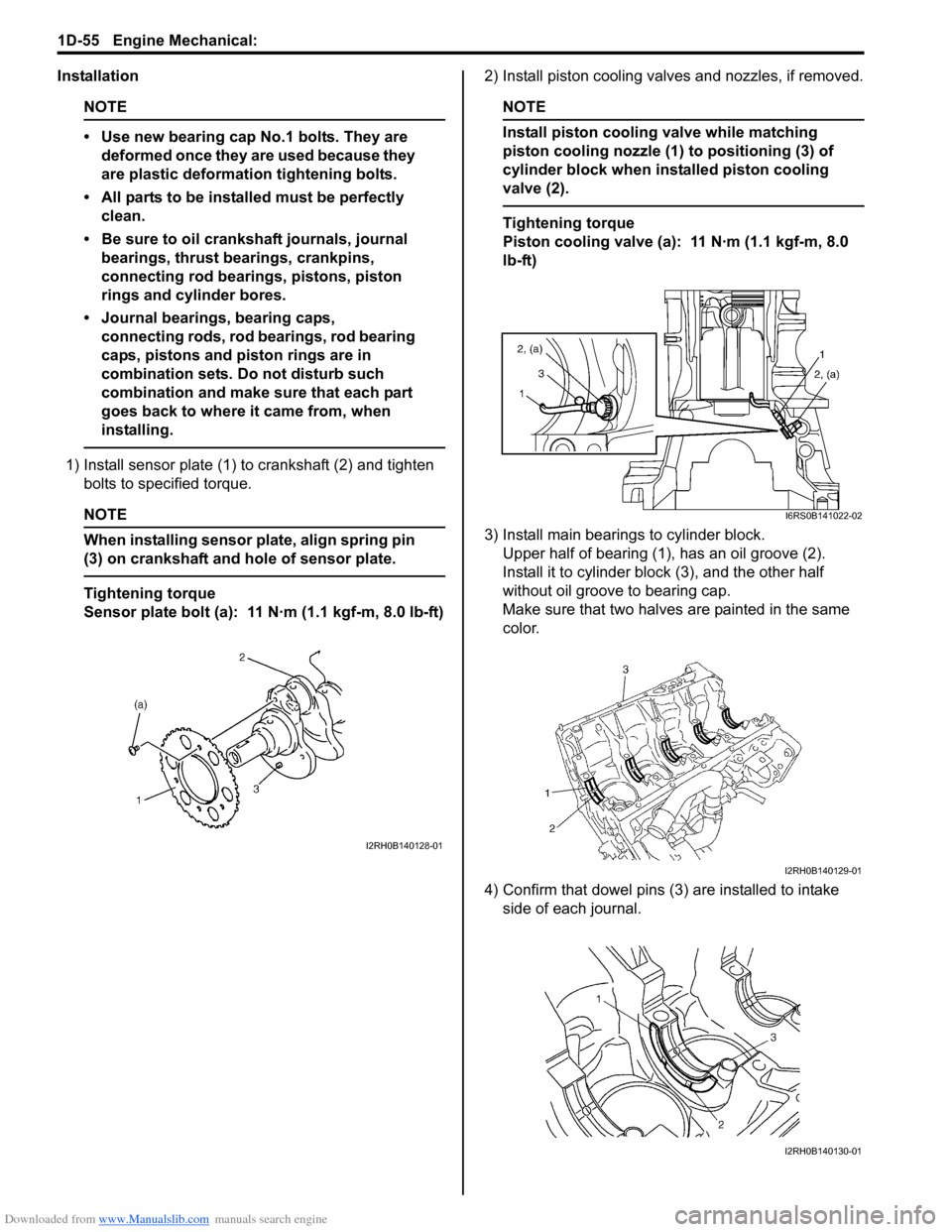
1) Install sensor plate (1) to crankshaft (2) and tighten bolts to spec ified torque.
NOTE
When installing sensor plate, align spring pin
(3) on crankshaft and hole of sensor plate.
Tightening torque
Sensor plate bolt (a): 11 N·m (1.1 kgf-m, 8.0 lb-ft) 2) Install piston cooling valves and nozzles, if removed.
NOTE
Install piston cooling valve while matching
piston cooling nozzle (1) to positioning (3) of
cylinder block when installed piston cooling
valve (2).
Tightening torque
Piston cooling valve (a): 11 N·m (1.1 kgf-m, 8.0
lb-ft)
3) Install main bearings to cylinder block. Upper half of bearing (1), has an oil groove (2).
Install it to cylinder block (3), and the other half
without oil groove to bearing cap.
Make sure that two halves are painted in the same
color.
4) Confirm that dowel pins (3 ) are installed to intake
side of each journal.
I2RH0B140128-01
I6RS0B141022-02
I2RH0B140129-01
I2RH0B140130-01
Page 351 of 1496
Downloaded from www.Manualslib.com manuals search engine Engine Mechanical: 1D-66
Special Tools and Equipment
Recommended Service MaterialS7RS0B1408001
NOTE
Required service material is also described in the following.
“Timing Chain Cover Components”
“Timing Chain and Chain Tensioner Components”
“Camshaft, Tappet and Shim Components”
“Valves and Cylinder Head Components”
“Pistons, Piston Rings, Connecting Rods and Cylinders Components”
“Main Bearings, Crankshaft and Cylinder Block Components”
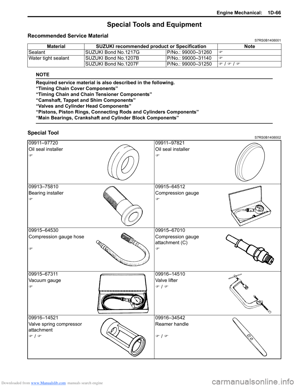
Special ToolS7RS0B1408002
Material SUZUKI recommended product or Specification Note
Sealant SUZUKI Bond No.1217G P/No.: 99000–31260�)
Water tight sealant SUZUKI Bond No.1207B P/No.: 99000–31140�)
SUZUKI Bond No.1207F P/No.: 99000–31250�) / �) / �)
09911–97720 09911–97821
Oil seal installer Oil seal installer
�)�)
09913–75810 09915–64512
Bearing installer Compression gauge
�)�)
09915–64530 09915–67010
Compression gauge hose Compression gauge
attachment (C)
�)�)
09915–67311 09916–14510
Vacuum gauge Valve lifter
�)�) / �)
09916–14521 09916–34542
Valve spring compressor
attachment Reamer handle
�) / �)�) / �)
Page 360 of 1496
Downloaded from www.Manualslib.com manuals search engine 1E-8 Engine Lubrication System:
Oil Pump ComponentsS7RS0B1506007
Oil Pump Removal and InstallationS7RS0B1506008
Oil pump is incorporated with timing chain cover.
For removal and installation, refer to “Timing Chain
Cover Removal and Installation in Section 1D”.
Oil Pump Disassembly and ReassemblyS7RS0B1506009
Disassembly1) Remove rotor plate (1) by removing its mounting bolts. 2) Remove outer rotor (1) and inner rotor (2).
3) Remove relief valve (1), spring (2) and retainer (3) by
removing circlip (4).
I4RS0A150010-01
1. Rotor plate 6. Rotor plate bolt10. Circlip
2. O-ring 7. Relief valve : 11 N⋅m (1.1 kgf-mm 8.0 lb-ft)
3. Outer rotor 8. Spring : Do not reuse.
4. Inner rotor 9. Retainer : Apply thin coat of engine oil to sliding surface.
5. Timing chain cover 10. Circlip
I2RH0B150018-01
I2RH0B150019-01
I2RH0B150020-01
Page 361 of 1496

Downloaded from www.Manualslib.com manuals search engine Engine Lubrication System: 1E-9
Reassembly1) Wash, clean and then dry all disassembled parts.
2) Apply thin coat of engine oil to inner and outer rotors, oil seal lip portion, inside surfaces of oil pump case
and plate.
3) Install outer (1) and inner rotors (2) to oil pump case.
4) Apply engine oil to relief valve (1) and spring (2), and install them with retainer (3) and new circlip (4) to
rotor plate (5).
5) Install rotor plate and tighten all bolts to specified torque. After installing plate, check to be sure that
rotors turn smoothly by hand (0.3 N ⋅m (0.03 kgf-m,
0.25 lb-ft) torque or below).
Tightening torque
Oil pump rotor plate bolt (a): 11 N·m (1.1 kgf-m,
8.0 lb-ft)Oil Pump InspectionS7RS0B1506010
Oil Seal
Check oil seal lip for fault or other damage. Replace as
necessary.
Oil Pump
• Check outer (1) and inner rotors (2), rotor plate, and oil pump case for excessive wear or damage.
• Check relief valve (1) for excessive wear or damage
and operates smoothly.
I2RH0B150019-01
I3RM0A150005-01
I2RH0B150022-01
I2RH0B150023-01
I2RH0B150019-01
I2RH0B150025-01
Page 362 of 1496
Downloaded from www.Manualslib.com manuals search engine 1E-10 Engine Lubrication System:
Radial clearance
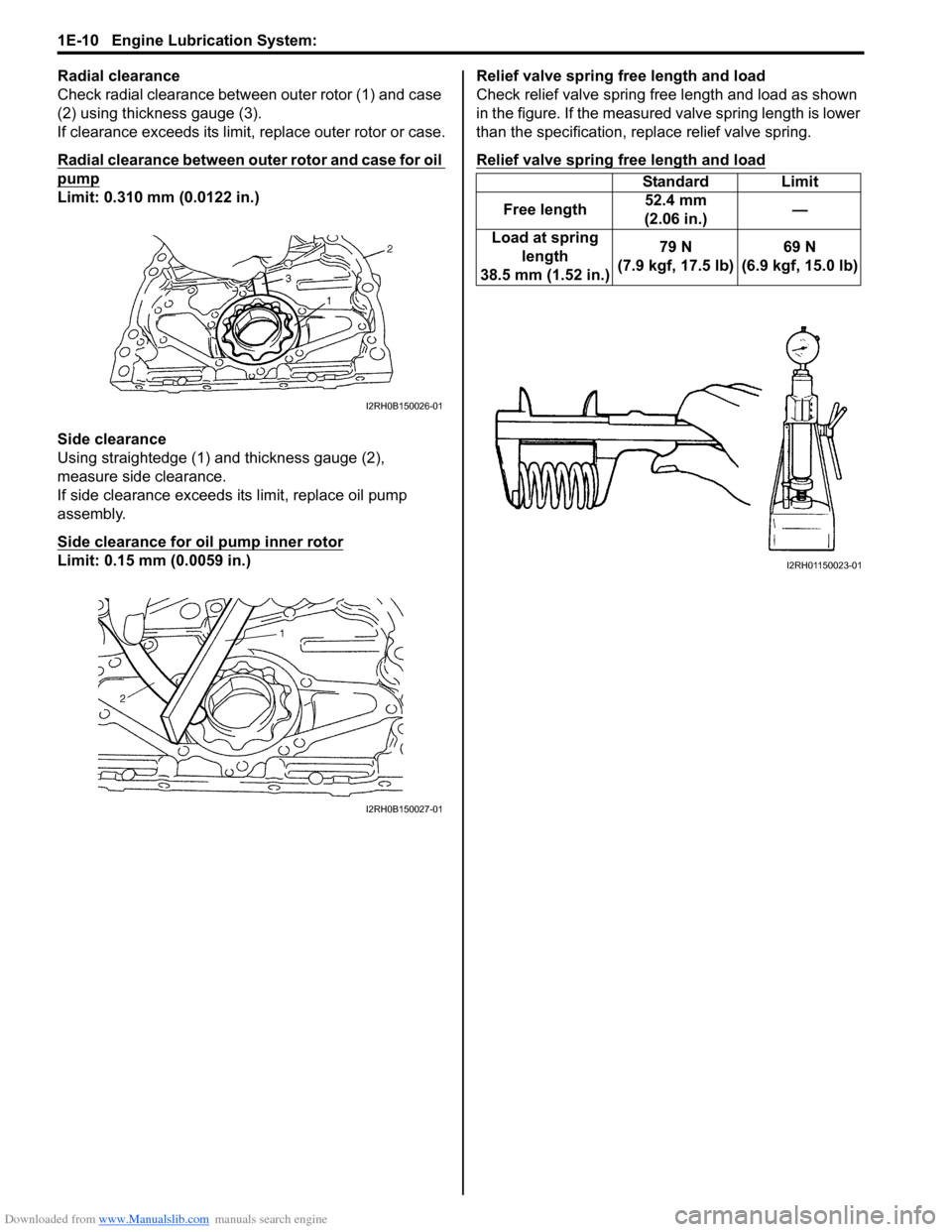
Check radial clearance between outer rotor (1) and case
(2) using thickness gauge (3).
If clearance exceeds its limit, replace outer rotor or case.
Radial clearance between outer rotor and case for oil
pump
Limit: 0.310 mm (0.0122 in.)
Side clearance
Using straightedge (1) and thickness gauge (2),
measure side clearance.
If side clearance exceeds its limit, replace oil pump
assembly.
Side clearance for oil pump inner rotor
Limit: 0.15 mm (0.0059 in.)Relief valve spring free length and load
Check relief valve spring free length and load as shown
in the figure. If the measured valve spring length is lower
than the specification, replace relief valve spring.
Relief valve spring free length and load
I2RH0B150026-01
I2RH0B150027-01
Standard Limit
Free length 52.4 mm
(2.06 in.) —
Load at spring length
38.5 mm (1.52 in.) 79 N
(7.9 kgf, 17.5 lb) 69 N
(6.9 kgf, 15.0 lb)
I2RH01150023-01
Page 677 of 1496
Downloaded from www.Manualslib.com manuals search engine Automatic Transmission/Transaxle: 5A-33
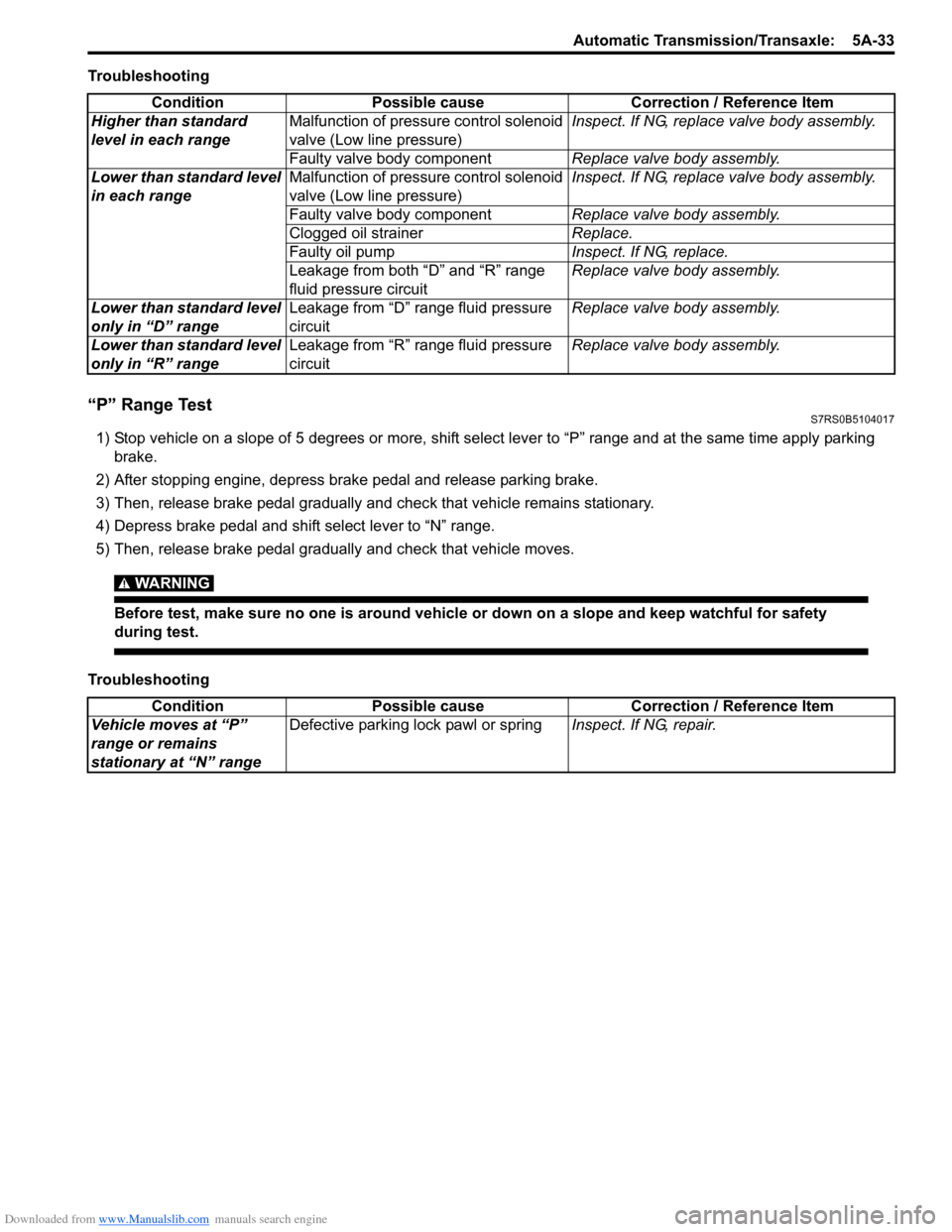
Troubleshooting
“P” Range TestS7RS0B5104017
1) Stop vehicle on a slope of 5 degrees or more, shift select lever to “P” range and at the same time apply parking brake.
2) After stopping engine, depress brake pedal and release parking brake.
3) Then, release brake pedal gradually and check that vehicle remains stationary.
4) Depress brake pedal and shift select lever to “N” range.
5) Then, release brake pedal gradually and check that vehicle moves.
WARNING!
Before test, make sure no one is around vehicle or down on a slope and keep watchful for safety
during test.
Troubleshooting Condition Possible cause Correction / Reference Item
Higher than standard
level in each range Malfunction of pressure control solenoid
valve (Low line pressure) Inspect. If NG, replace valve body assembly.
Faulty valve body component Replace valve body assembly.
Lower than standard level
in each range Malfunction of pressure control solenoid
valve (Low line pressure) Inspect. If NG, replace valve body assembly.
Faulty valve body component Replace valve body assembly.
Clogged oil strainer Replace.
Faulty oil pump Inspect. If NG, replace.
Leakage from both “D” and “R” range
fluid pressure circuit Replace valve body assembly.
Lower than standard level
only in “D” range Leakage from “D” range fluid pressure
circuit Replace valve body assembly.
Lower than standard level
only in “R” range Leakage from “R” range fluid pressure
circuit Replace valve body assembly.
Condition
Possible cause Correction / Reference Item
Vehicle moves at “P”
range or remains
stationary at “N” range Defective parking lock pawl or spring
Inspect. If NG, repair.