2008 SUZUKI SWIFT steering parts
[x] Cancel search: steering partsPage 432 of 1496
Downloaded from www.Manualslib.com manuals search engine 2A-1 Suspension General Diagnosis:
Suspension
Suspension General Diagnosis
Diagnostic Information and Procedures
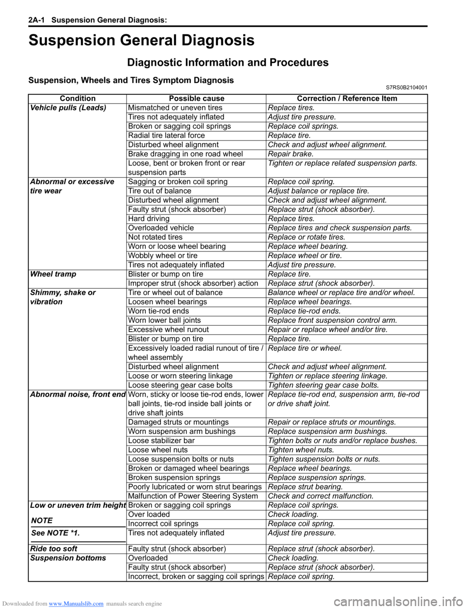
Suspension, Wheels and Tires Symptom DiagnosisS7RS0B2104001
ConditionPossible cause Correction / Reference Item
Vehicle pulls (Leads) Mismatched or uneven tires Replace tires.
Tires not adequately inflated Adjust tire pressure.
Broken or sagging coil springs Replace coil springs.
Radial tire lateral force Replace tire.
Disturbed wheel alignment Check and adjust wheel alignment.
Brake dragging in one road wheel Repair brake.
Loose, bent or broken front or rear
suspension parts Tighten or replace related suspension parts.
Abnormal or excessive
tire wear Sagging or broken coil spring
Replace coil spring.
Tire out of balance Adjust balance or replace tire.
Disturbed wheel alignment Check and adjust wheel alignment.
Faulty strut (shock absorber) Replace strut (shock absorber).
Hard driving Replace tires.
Overloaded vehicle Replace tires and check suspension parts.
Not rotated tires Replace or rotate tires.
Worn or loose wheel bearing Replace wheel bearing.
Wobbly wheel or tire Replace wheel or tire.
Tires not adequately inflated Adjust tire pressure.
Wheel tramp Blister or bump on tire Replace tire.
Improper strut (shock absorber) action Replace strut (shock absorber).
Shimmy, shake or
vibration Tire or wheel out of balance
Balance wheel or replace tire and/or wheel.
Loosen wheel bearings Replace wheel bearings.
Worn tie-rod ends Replace tie-rod ends.
Worn lower ball joints Replace front suspension control arm.
Excessive wheel runout Repair or replace wheel and/or tire.
Blister or bump on tire Replace tire.
Excessively loaded radial runout of tire /
wheel assembly Replace tire or wheel.
Disturbed wheel alignment Check and adjust wheel alignment.
Loose or worn steering linkage Tighten or replace steering linkage.
Loose steering gear case bolts Tighten steering gear case bolts.
Abnormal noise, front end Worn, sticky or loose tie-rod ends, lower
ball joints, tie-rod in side ball joints or
drive shaft joints Replace tie-rod end, su
spension arm, tie-rod
or drive shaft joint.
Damaged struts or mountings Repair or replace struts or mountings.
Worn suspension arm bushings Replace suspension arm bushings.
Loose stabilizer bar Tighten bolts or nuts and/or replace bushes.
Loose wheel nuts Tighten wheel nuts.
Loose suspension bolts or nuts Tighten suspension bolts or nuts.
Broken or damaged wheel bearings Replace wheel bearings.
Broken suspension springs Replace suspension springs.
Poorly lubricated or worn strut bearings Replace strut bearing.
Malfunction of Power Steering System Check and correct malfunction.
Low or uneven trim height
NOTE
See NOTE *1.
Broken or sagging coil springs Replace coil springs.
Over loaded Check loading.
Incorrect coil springs Replace coil spring.
Tires not adequately inflated Adjust tire pressure.
Ride too soft Faulty strut (shock absorber) Replace strut (shock absorber).
Suspension bottoms Overloaded Check loading.
Faulty strut (shock absorber) Replace strut (shock absorber).
Incorrect, broken or sagging coil springs Replace coil spring.
Page 447 of 1496
Downloaded from www.Manualslib.com manuals search engine Front Suspension: 2B-14
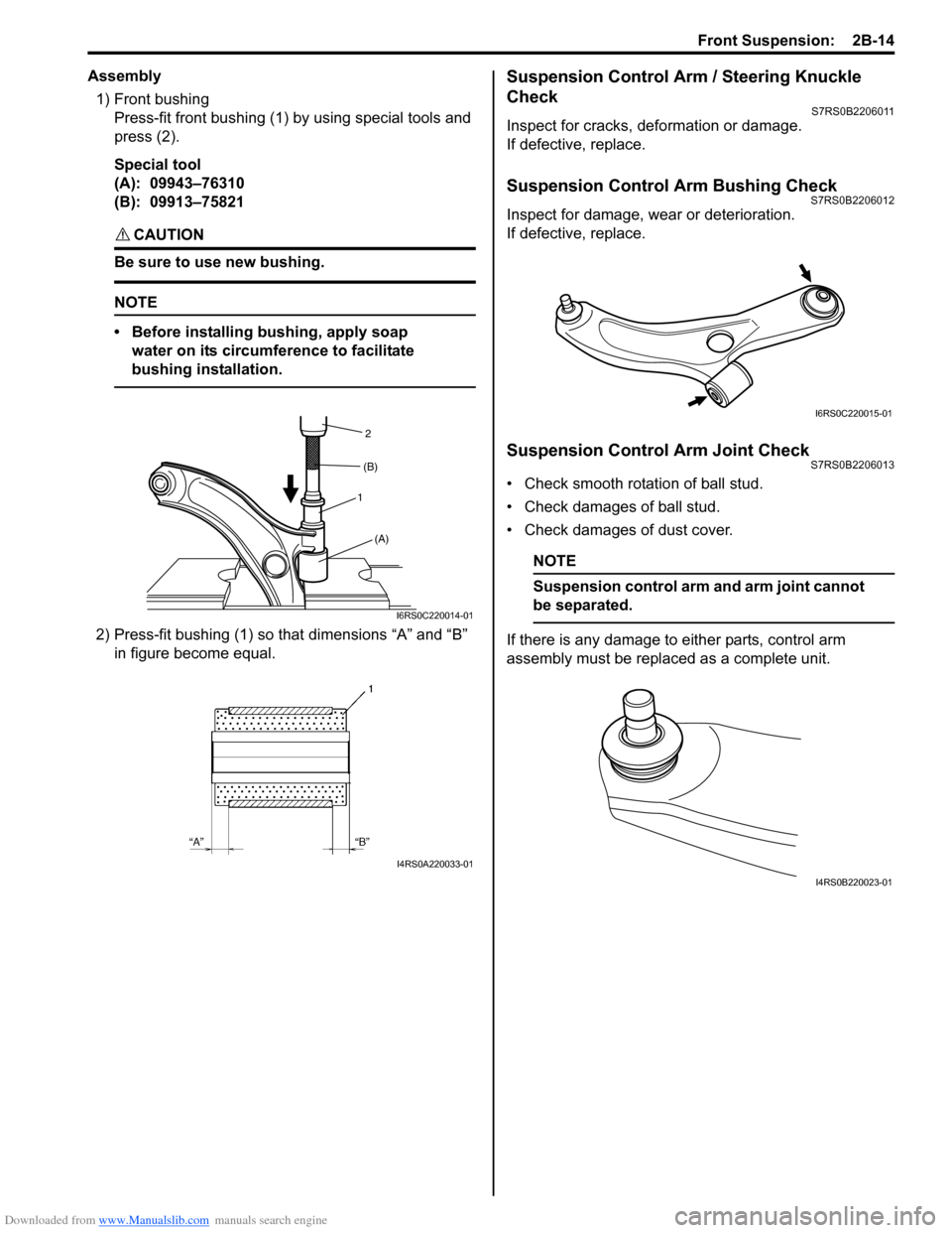
Assembly1) Front bushing Press-fit front bushing (1) by using special tools and
press (2).
Special tool
(A): 09943–76310
(B): 09913–75821
CAUTION!
Be sure to use new bushing.
NOTE
• Before installing bushing, apply soap water on its circumference to facilitate
bushing installation.
2) Press-fit bushing (1) so that dimensions “A” and “B” in figure become equal.
Suspension Control Arm / Steering Knuckle
Check
S7RS0B2206011
Inspect for cracks, deformation or damage.
If defective, replace.
Suspension Control Arm Bushing CheckS7RS0B2206012
Inspect for damage, wear or deterioration.
If defective, replace.
Suspension Control Arm Joint CheckS7RS0B2206013
• Check smooth rotation of ball stud.
• Check damages of ball stud.
• Check damages of dust cover.
NOTE
Suspension control a rm and arm joint cannot
be separated.
If there is any damage to either parts, control arm
assembly must be replaced as a complete unit.
1 2
(A)
(B)
I6RS0C220014-01
I4RS0A220033-01
I6RS0C220015-01
I4RS0B220023-01
Page 452 of 1496

Downloaded from www.Manualslib.com manuals search engine 2B-19 Front Suspension:
13) Install suspension control arm referring to
“Suspension Control Arm / Bushing Removal and
Installation”.
14) Connect couplers of torque sensor and P/S motor.
15) Connect tie-rod ends to knuckles (right & left) and then install cotter pins referring to “Tie-Rod End
Removal and Installa tion in Section 6C”.
16) Be sure that steering wheel and brake discs (right & left) are all straight-ahead position and then insert
steering lower shaft (5) into steering pinion shaft (3)
with matching marks (4).
17) Tighten steering shaft joint lower bolt (1) and upper bolt (2) to specified torque (Lower side first and then
upper side).
Tightening torque
Steering shaft joint bolt (a): 25 N·m (2.5 kgf-m,
18.5 lb-ft)
18) Install both wheels and tighten wheel bolts to specified torque.
Tightening torque
Wheel bolt: 85 N·m (8.5 kgf-m, 61.5 lb-ft)
19) Lower hoist.
20) Check toe setting. Adjust as required refer to “Front Wheel Alignment Inspection and Adjustment”.
Front Suspension Frame CheckS7RS0B2206016
Inspect for cracks, deformation or damage.
If defective, replace.
Front Stabilizer Bar, Bushing and/or Joint
Check
S7RS0B2206017
Stabilizer Bar
Inspect for damage or deformation.
If defective, replace.
Stabilizer Bushing
Inspect for damage, wear or deterioration.
If defective, replace.
Stabilizer Joint
1) Check for smooth rotation.
2) Check damages of ball stud.
3) Check damages of dust cover.
NOTE
Stabilizer joint (1) cannot be disassembled.
If there is any damage to either parts, stabilizer joint
assembly must be replaced as a complete unit.
Front Suspension Fasteners CheckS7RS0B2206018
Check each bolt and nut fastening suspension parts for
tightness. Tighten loose one, if any, to specified torque,
referring to “Front Suspension Construction”.
5
4
1, (a)
3
2, (a)
1, (a)
5
I4RS0B630016-01
I4RS0A220054-01
I4RS0A220052-01
I4RS0A220056-01
1
I4RH01220007-01
Page 595 of 1496
Downloaded from www.Manualslib.com manuals search engine Electronic Stability Program: 4F-21
Stability control (ACTIVE, INACTIVE): This indicates
stability control in acti vation / deactivation.
TCS control (brake) ( ACTIVE, INACTIVE): This
indicates brake function of TCS in activation /
deactivation.
TCS control (engine) (ACTIVE, INACTIVE): This
indicates torque control of TCS in activation /
deactivation. ESP®
off state (cont) (ESP ® ON, ESP ® OFF): State
of ESP ® OFF switch.
Steering angle Sen (Neutral, NON newtral): This
indicates steering wheel angle measured by steering
angle sensor is in straight-ahead or not.
Visual InspectionS7RS0B4604059
Check the following parts and systems visually.
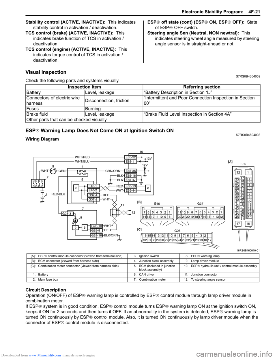
ESP ® Warning Lamp Does Not Come ON at Ignition Switch ONS7RS0B4604008
Wiring Diagram
Circuit Description
Operation (ON/OFF) of ESP ® warning lamp is controlled by ESP ® control module through lamp driver module in
combination meter.
If ESP ® system is in good condition, ESP ® control module turns ESP ® warning lamp ON at the ignition switch ON,
keeps it ON for 2 seconds and then turns it OFF. If an abnormality in the system is detected, ESP ® warning lamp is
turned ON continuously by ESP ® control module. Also, it is turned ON continuously by lamp driver module when the
connector of ESP ® control module is disconnected.Inspection Item Referring section
Battery Level, leakage “Battery Description in Section 1J”
Connectors of electric wire
harness Disconnection, friction“Intermittent and Poor Connec
tion Inspection in Section
00”
Fuses Burning
Brake fluid Level, leakage “Brake Fluid Level Inspection in Section 4A”
Other parts that can be checked visually
[A] E85
161
15
2
3
4
5
6
7
8
9
10
11
12
13
14
17
18
19
20
21
22
23
24
25
26
27
28
29
30
31
3233
34
35
36
37
38
39
40
41
42
43
44
45
46
47
WHTGRN
3
E85-13
E85-44REDWHT6 5E46-1E46-2
4 10
6
E85-16
E85-47BLKBLK
8
9
BLK/ORN
REDWHT
REDWHT
G37-4G37-2
G28-10G28-8
G28-16
12V
12VE85-32E85-1
E85-35
WHT/REDWHT/BLU
GRN/ORN
6
2
1
7 1112[B]
G37
E46124
53
67
891011121314124
53
67
891011
1213141516171819202122
[C] G28
12345678910111213141516
17181920212223242526272829303132
G28-31
RED/BLK
I6RS0B460010-01
[A]: ESP ® control module connector (viewed from terminal side) 3. Ignition switch 8. ESP ® warning lamp
[B]: BCM connector (viewed from harness side) 4. Junction block assembly 9. Lamp driver module
[C]: Combination meter connector (viewed from harness side) 5. BCM (included in junction
block assembly) 10. ESP
® hydraulic unit / control module assembly
1. Battery 6. CAN driver 11. Junction connector
2. Main fuse box 7. Combination meter 12. To steering angle sensor
Page 657 of 1496
Downloaded from www.Manualslib.com manuals search engine Automatic Transmission/Transaxle: 5A-13
Component Location
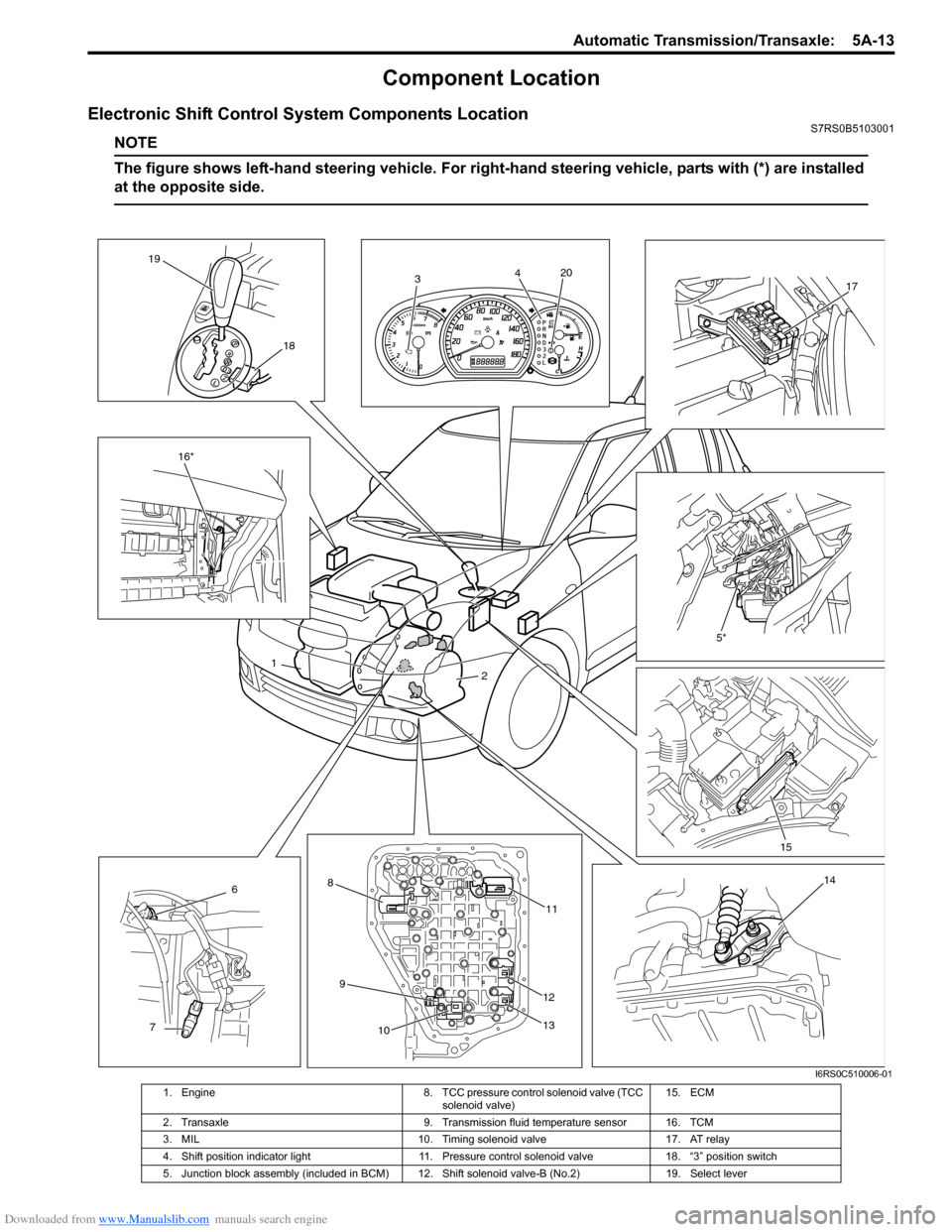
Electronic Shift Control System Components LocationS7RS0B5103001
NOTE
The figure shows left-hand steering vehicle. For right-hand steering vehicle, parts with (*) are installed
at the opposite side.
3 4
5*
1 2
6
7 8
9 10 11
12
13 14
16*
18
19
17
15
20
I6RS0C510006-01
1. Engine
8. TCC pressure control solenoid valve (TCC
solenoid valve) 15. ECM
2. Transaxle 9. Transmission fluid temperature sensor 16. TCM
3. MIL 10. Timing solenoid valve17. AT relay
4. Shift position indicator light 11. Pressure control solenoid valve18. “3” position switch
5. Junction block assembly (included in BCM) 12. Shift solenoid valve-B (No.2)19. Select lever
Page 870 of 1496
Downloaded from www.Manualslib.com manuals search engine 6A-1 Steering General Diagnosis:
Steeri ng
Steering General Diagnosis
Precautions
Precautions for Steering DiagnosisS7RS0B6100001
Since the problems in steering involve several systems, they must all be considered when diagnosing a complaint. To
avoid using the wrong symptom, always road test the vehicl e first. Proceed with the following preliminary inspection
and correct any defects which are found.
1) Inspect tires for proper pressure and uneven wear.
2) Raise vehicle on a hoist and inspect steering system for loose or damaged parts.
3) Spin front wheels. Inspect for out-of-round tires, out- of-balance tires, bent rims, loosen and/or rough wheel
bearings.
Page 877 of 1496
Downloaded from www.Manualslib.com manuals search engine Steering Wheel and Column: 6B-6
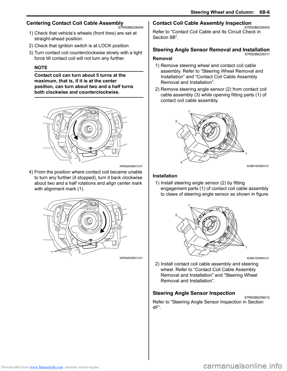
Centering Contact Coil Cable AssemblyS7RS0B6206004
1) Check that vehicle’s wheels (front tires) are set at straight-ahead position.
2) Check that ignition swit ch is at LOCK position.
3) Turn contact coil counterclockwise slowly with a light force till contact coil will not turn any further.
NOTE
Contact coil can turn about 5 turns at the
maximum, that is, if it is at the center
position, can turn about two and a half turns
both clockwise and counterclockwise.
4) From the position where contact coil became unable to turn any further (it stopped), turn it back clockwise
about two and a half rotations and align center mark
with alignment mark (1).
Contact Coil Cable Assembly InspectionS7RS0B6206005
Refer to “Contact Coil Cable and Its Circuit Check in
Section 8B”.
Steering Angle Sensor Removal and InstallationS7RS0B6206011
Removal
1) Remove steering wheel and contact coil cable assembly. Refer to “Ste ering Wheel Removal and
Installation” and “Contact Coil Cable Assembly
Removal and Installation”.
2) Remove steering angle sensor (2) from contact coil cable assembly (3) while op ening fitting parts (1) of
contact coil cable assembly.
Installation 1) Install steering angle sensor (2) by fitting engagement parts (1) of contact coil cable assembly
to claws of steering angle sensor as shown in figure.
2) Install contact coil cable assembly and steering wheel. Refer to “Contact Coil Cable Assembly
Removal and Installation” and “Steering Wheel
Removal and Installation”.
Steering Angle Sensor InspectionS7RS0B6206012
Refer to “Steering Angle Sens or Inspection in Section
4F”.
I4RS0A620012-01
1
I4RS0A620013-01
1
1
2
3I6JB01620003-01
1
1
2
I6JB01620004-01
Page 883 of 1496

Downloaded from www.Manualslib.com manuals search engine Power Assisted Steering System: 6C-1
Steeri ng
Power Assisted Steering System
Precautions
Steering System NoteS7RS0B6300001
NOTE
All steering gear fasteners are important attaching parts in that they could affect the performance of
vital parts and systems, and/or could result in major repair expense. They must be replaced with one of
the same part number or with an equivalent part if replacement becomes necessary. Do not use a
replacement part of lesser quality or substitute design. Torque values must be used as specified
during reassembly to assure proper retention of these parts.
Precautions in Diagnosing TroublesS7RS0B6300002
• Take a note of DTC indicated on the SUZUKI scan tool.
• Before inspection, be sure to read “Pre cautions for Electrical Circuit Service in Section 00” and understand what is
written there.
• DTC C1122 (engine speed signal failure) is indicated when ignition switch is at ON position and engine is not
running, but it means there is nothing abnormal if indica tion changes to a normal one when engine is started.
• As DTC is stored in memory of the P/S control module, be sure to clear memory after repair by performing the
procedure described in “DTC Clearance”.