2008 SUZUKI SWIFT serial data link circuit check
[x] Cancel search: serial data link circuit checkPage 601 of 1496

Downloaded from www.Manualslib.com manuals search engine Electronic Stability Program: 4F-27
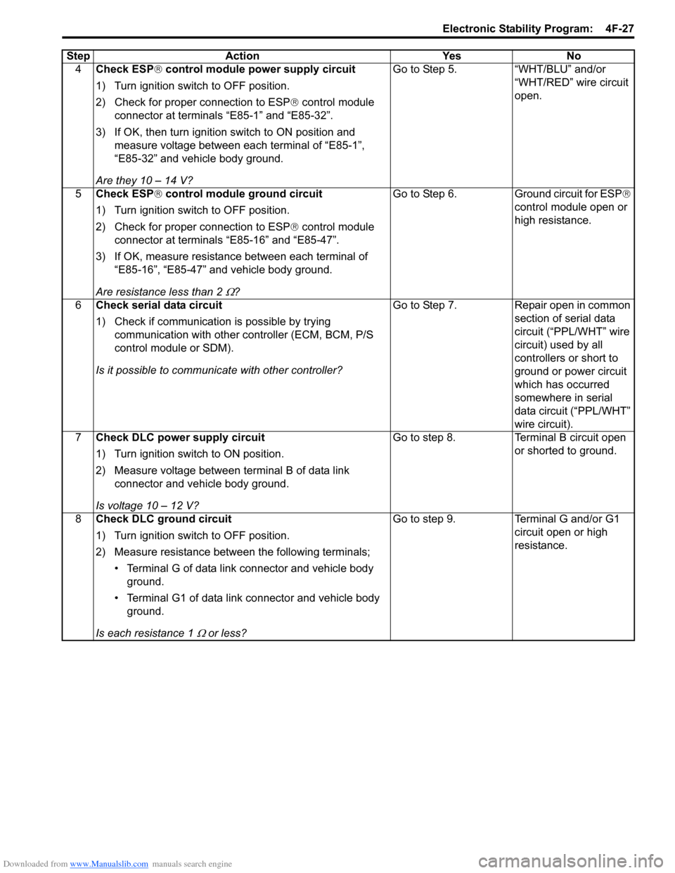
4Check ESP ® control module power supply circuit
1) Turn ignition switch to OFF position.
2) Check for proper connection to ESP ® control module
connector at terminals “E85-1” and “E85-32”.
3) If OK, then turn ignition switch to ON position and measure voltage between each terminal of “E85-1”,
“E85-32” and vehicle body ground.
Are they 10 – 14 V? Go to Step 5. “WHT/BLU” and/or
“WHT/RED” wire circuit
open.
5 Check ESP ® control module ground circuit
1) Turn ignition switch to OFF position.
2) Check for proper connection to ESP ® control module
connector at terminals “E85-16” and “E85-47”.
3) If OK, measure resistance between each terminal of “E85-16”, “E85-47” and vehicle body ground.
Are resistance less than 2
Ω? Go to Step 6. Ground circuit for ESP
®
control module open or
high resistance.
6 Check serial data circuit
1) Check if communication is possible by trying
communication with other c ontroller (ECM, BCM, P/S
control module or SDM).
Is it possible to commun icate with other controller? Go to Step 7. Repair open in common
section of serial data
circuit (“PPL/WHT” wire
circuit) used by all
controllers or short to
ground or power circuit
which has occurred
somewhere in serial
data circuit (“PPL/WHT”
wire circuit).
7 Check DLC power supply circuit
1) Turn ignition switch to ON position.
2) Measure voltage between terminal B of data link
connector and vehicle body ground.
Is voltage 10 – 12 V? Go to step 8. Terminal B circuit open
or shorted to ground.
8 Check DLC ground circuit
1) Turn ignition switch to OFF position.
2) Measure resistance between the following terminals;
• Terminal G of data link connector and vehicle body ground.
• Terminal G1 of data link connector and vehicle body ground.
Is each resistance 1
Ω or less? Go to step 9. Terminal G and/or G1
circuit open or high
resistance.
Step Action Yes No
Page 867 of 1496

Downloaded from www.Manualslib.com manuals search engine Table of Contents 6- i
6
Section 6
CONTENTS
Steering
Precautions ................................................. 6-1
Precautions............................................................. 6-1
Precautions on Steering........................................ 6-1
Steering General Diagnosi s.................... 6A-1
Precautions........................................................... 6A-1
Precautions for Steering Diagnosis ..................... 6A-1
Diagnostic Information and Procedures ............ 6A-2 Steering Symptom Diagnosis .............................. 6A-2
Steering Wheel and Column ................... 6B-1
Precautions........................................................... 6B-1
Service Precautions of Steering Wheel and Column.............................................................. 6B-1
General Description ............................................. 6B-1 Steering Wheel and Column Construction .......... 6B-1
Diagnostic Information and Procedures ............ 6B-2 Checking Steering Column for Accident Damage ............................................................ 6B-2
Repair Instructions .............................................. 6B-3 Steering Wheel and Column Construction .......... 6B-3
Steering Wheel Removal and Installation ........... 6B-4
Contact Coil Cable Assembly Removal and Installation ......................................................... 6B-5
Centering Contact Coil Cable Assembly ............. 6B-6
Contact Coil Cable Assembly Inspection ............ 6B-6
Steering Angle Sensor Removal and Installation ......................................................... 6B-6
Steering Angle Sensor Inspection ....................... 6B-6
Steering Column Removal and Installation ......... 6B-7
Steering Column Inspecti on ................................ 6B-8
Ignition Switch Cylinder Assembly Removal and Installation (Non- Keyless Start Model)...... 6B-9
Steering Lock Assembly (Ignition Switch) Removal and Installation................................... 6B-9
Steering Lower Shaft Removal and Installation ....................................................... 6B-10
Specifications ..................................................... 6B-11
Tightening Torque Specifications ...................... 6B-11
Special Tools and Equipmen t ........................... 6B-11
Special Tool ...................................................... 6B-11
Power Assisted Steering System........... 6C-1
Precautions........................................................... 6C-1 Steering System Note .........................................6C-1
Precautions in Diagnosing Troubles ...................6C-1
General Description .............................................6C-2 P/S System Description ......................................6C-2
EPS Diagnosis General Descr iption ...................6C-3
On-Board Diagnostic System Description ...........6C-3
Schematic and Routing Diagram ........................6C-4 EPS System Wiring Circuit Diagram ...................6C-4
Diagnostic Information and Procedures ............6C-5 EPS System Check .............. ...............................6C-5
“EPS” Warning Light Check . ...............................6C-8
DTC Check..........................................................6C-8
DTC Clearance ...................................................6C-9
DTC Table ...........................................................6C-9
Scan Tool Data .................................................6C-11
Visual Inspection ...............................................6C-12
P/S System Symptom Diagnosis ......................6C-12
Serial Data Link Circuit Check ..........................6C-13
“EPS” Warning Light Do es Not Come ON with
Ignition Switch Turn ed ON before Engine
Starts ...............................................................6C-15
“EPS” Warning Light Remains ON Steady after Engine Starts ..........................................6C-16
DTC C1113: Steering Torque Sensor (Main and Sub) Circuit Correlation ............................6C-17
DTC C1114: Steering Torque Sensor Reference Power Supply Circuit .....................6C-19
DTC C1117: Steering Torque Sensor Failure Signal Circuit Low ...........................................6C-21
DTC C1118: Steering Torque Sensor Failure Signal Circuit High...........................................6C-22
DTC C1119: Steering Torque Sensor Power Supply Circuit ..................................................6C-24
DTC C1121 / C1123 / C1124: VSS Circuit
Failure .............................................................6C-26
DTC C1122: Engine Speed Signal....................6C-28
DTC C1141 / C1142 / C1143 / C1145: P/S Motor Circuit Failure ........................................6C-30
DTC C1153: P/S Control Module Power Supply Circuit Voltage Low .............................6C-32
DTC C1155: P/S Control Module Failure ..........6C-33
P/S Control Module Power Supply and Ground Circuit Check ......................................6C-34
Inspection of P/S Control Module and Its Circuits ............................................................6C-35
Page 887 of 1496

Downloaded from www.Manualslib.com manuals search engine Power Assisted Steering System: 6C-5
Terminal Arrangement of P/S Control Module Coupler (Viewed from Harness Side)
Diagnostic Information and Procedures
EPS System CheckS7RS0B6304001
WARNING!
Carry out test drive in light traffic area to prevent an accident.
Refer to the following items for the details of each step.Terminal Circuit Terminal Circuit
E49-1 Main power supply for internal memory
and EPS motor E52-9 Ground for torque sensors
E49-2 Ground for P/S control module E52-10 —
E51-1 Motor output 1 E52-11 Serial communication for data link
connector
E51-2 Motor output 2 E52-12 Engine speed signal
E52-1 Ignition switch signal for P/S control
module E52-13 —
E52-2 — E52-14 P/S operation signal (idle up signal)
E52-3 — E52-15 —
E52-4 Vehicle speed signal E52-16 Torque sensor internal failure signal
E52-5 “EPS” warning light E52-17 —
E52-6 Torque sensor signal (Sub) E52-18 Torque sensor signal (Main)
E52-7 — E52-19 Ground for shield wire
E52-8 Main power supply for torque sensor E52-20 5 V reference power supply for torque
sensor
Step
Action YesNo
1 �) Customer complaint analysis
1) Perform customer complaint analysis referring to “Customer Complaint Analysis”.
Was customer complaint analysis performed? Go to Step 2.
Perform customer
complaint analysis.
2 �) DTC check, record and clearance
1) Check for DTC (including pending DTC) referring to “DTC Check”, Record and Clearance.
Is there any DTC(s)? Print DTC or write them
down and clear them by
referring to “DTC
Clearance” and go to
St ep 3 .Go to Step 4.
3 �) Visual inspection
1) Perform visual inspection referring to “Visual Inspection”.
Is there any faulty condition? Repair or replace
malfunction part, and go
to Step 11.
Go to Step 5.
4 �) Visual inspection
1) Perform visual inspection referring to “Visual Inspection”.
Is there any faulty condition? Repair or replace
malfunction part, and go
to Step 11.
Go to Step 8.
5 �) Trouble symptom confirmation
1) Confirm trouble symptom referring to “Trouble Symptom Confirmation”.
Is trouble symptom identified? Go to Step 6.
Go to Step 7.
6 �) Rechecking and record of DTC
1) Recheck for DTC referring to “DTC Check”.
Is there any DTC(s)? Go to Step 9.
Go to Step 8.
Page 891 of 1496

Downloaded from www.Manualslib.com manuals search engine Power Assisted Steering System: 6C-9
3) Start engine.
4) Read DTC according to the instructions displayed on
SUZUKI scan tool. For further details, refer to
operator’s manual for SUZUKI scan tool.
NOTE
• If communication between SUZUKI scan tool and the vehicle can not be
established, perform “Serial Data Link
Circuit Check”.
• DTC C1122 (engine speed signal failure) is indicated when ignition switch is at ON
position and engine is not running, but it
means there is nothing abnormal if
indication changes to a normal one when
engine is started.
5) After completing the check, turn ignition switch to
OFF position and disconnect SUZUKI scan tool from
DLC.
DTC ClearanceS7RS0B6304004
1) Turn ignition switch to OFF position.
2) Connect SUZUKI scan tool to data link connector (DLC) (1) located on underside of instrument panel
at driver’s seat side.
Special tool
(A): SUZUKI scan tool
3) Turn ignition switch to ON position.
4) Erase DTC according to the instructions displayed on SUZUKI scan tool. For further details, refer to
operator’s manual for SUZUKI scan tool.
5) After completing the clearance, turn ignition switch to OFF position and disconnect SUZUKI scan tool from
DLC.
DTC TableS7RS0B6304005
CAUTION!
Be sure to perform the “EPS Syst em Check” before starting troubleshooting corresponding to each
DTC.
(A)
1
I4RS0B450003-01
DTC No. Detecting item Detecting condition
(DTC will set when detecting) Trouble area MIL
No
CODES Normal — — —
�) C1113 Steering torque sensor (Main
and Sub) circuit correlation Voltage difference between torque
sensor main signal and sub signal
is more than 0.6 V for 1 second
continuously. • Torque sensor signal circuit
• Torque sensor
• P/S control module
1 driving
cycle
�) C1114 Steering torque sensor
reference power supply
circuit Circuit voltage of torque sensor 5
V reference power supply voltage
is more than 5.7 V or less than 4.3
V for 1 second continuously. • Torque sensor circuit
• Torque sensor
• P/S control module
1 driving
cycle
�) C1117 Steering torque sensor
failure signal circuit low Torque sensor internal failure
signal circuit voltage is less than
1.7 V when ignition switch turned
ON.
• Torque sensor signal circuit
• Torque sensor
• P/S control module1 driving
cycle
�) C1118 Steering torque sensor
failure signal circuit high Torque sensor internal failure
signal circuit voltage is more than
3.7 V for 1 second continuously. 1 driving
cycle
�) C1119 Steering torque sensor
power supply circuit Circuit voltage of torque sensor
main power supply
is less than
7.5 V for 1 second continuously. • Torque sensor circuit
• Torque sensor
• P/S control module
1 driving
cycle
Page 895 of 1496

Downloaded from www.Manualslib.com manuals search engine Power Assisted Steering System: 6C-13
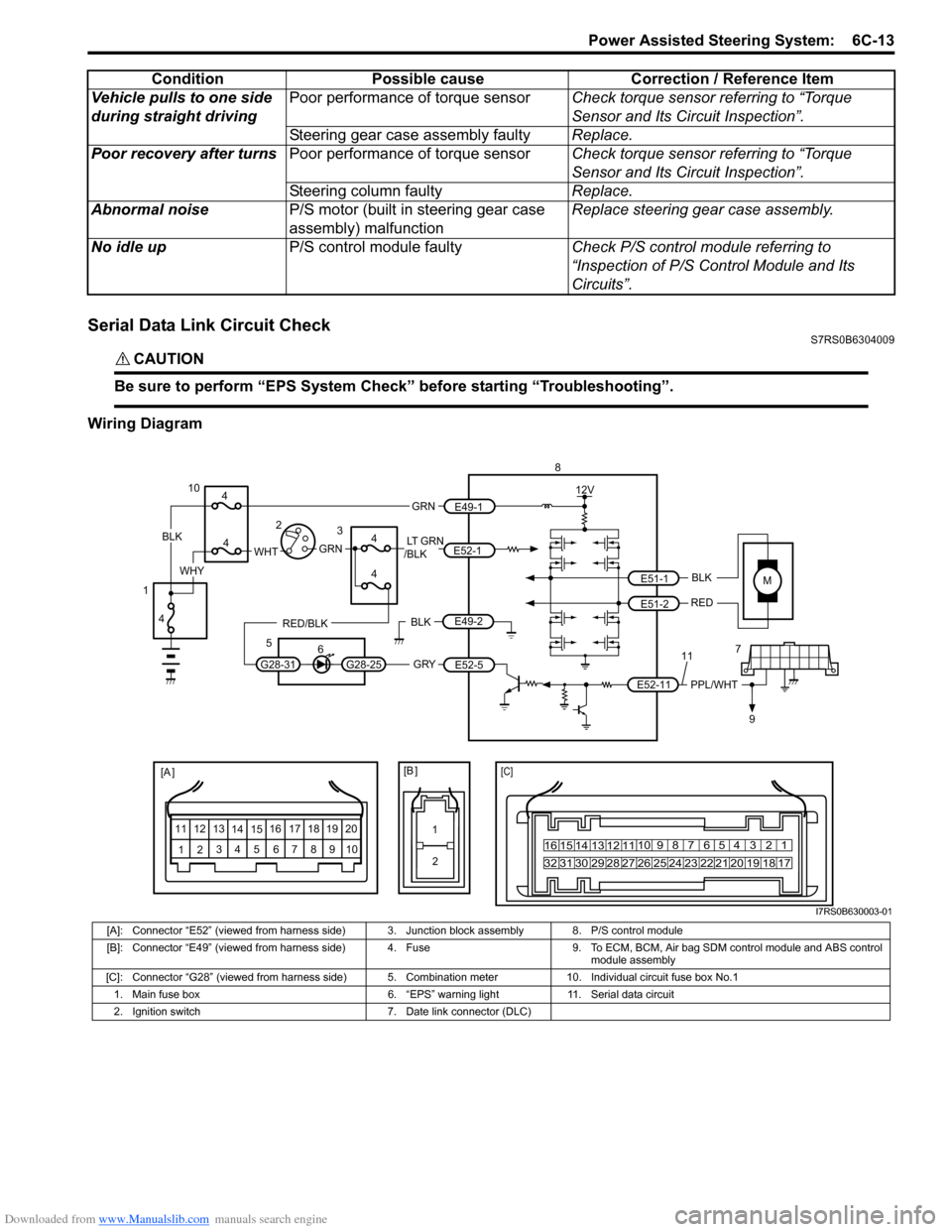
Serial Data Link Circuit CheckS7RS0B6304009
CAUTION!
Be sure to perform “EPS System Check” before starting “Troubleshooting”.
Wiring DiagramVehicle pulls to one side
during straight driving
Poor performance of torque sensor
Check torque sensor referring to “Torque
Sensor and Its Circuit Inspection”.
Steering gear case assembly faulty Replace.
Poor recovery after turns Poor performance of torque sensor Check torque sensor referring to “Torque
Sensor and Its Circuit Inspection”.
Steering column faulty Replace.
Abnormal noise P/S motor (built in steering gear case
assembly) malfunction Replace steering gear case assembly.
No idle up P/S control module faulty Check P/S control module referring to
“Inspection of P/S Control Module and Its
Circuits”.
Condition Possible cause Correction / Reference Item
MBLK
RED
E52-11 E51-1
E51-2PPL/WHT
[A ]
12
3
4 5 67
89
11
10
12 13
141516
17 18 19 2010 9 8 7654 3 21
16 15 14 13 12 11
26 25 24 2322 21 20 19 18 17
32 31 30 29 28 27
[C]
8
79
12V
[B ]
11
12
GRY
LT GRN
/BLK
E52-1
E52-5
E49-1
GRNGRNWHTBLK
WHY
G28-25G28-31
RED/BLK
10
3
4
4
5 6
4
4
1 2
4
E49-2BLK
I7RS0B630003-01
[A]: Connector “E52” (viewed from harness side) 3. Junction block assembly 8. P/S control module
[B]: Connector “E49” (viewed from harness side) 4. Fuse 9. T o ECM, BCM, Air bag SDM control module and ABS control
module assembly
[C]: Connector “G28” (viewed from harness side) 5. Comb ination meter 10. Individual circuit fuse box No.1
1. Main fuse box 6. “EPS” warning light 11. Serial data circuit
2. Ignition switch 7. Date link connector (DLC)
Page 934 of 1496

Downloaded from www.Manualslib.com manuals search engine 7-ii Table of Contents
Recommended Service Material ....................... 7B-33
Special Tool ...................................................... 7B-33
Automatic Type .................... .................................7B-34
Precautions.........................................................7B-34 A/C System Caution .......................................... 7B-34
Precautions in Diagnosing Trouble ................... 7B-34
Precautions on Servicing A/C System .............. 7B-34
General Description .......... .................................7B-34
Auto A/C System Descript ion ............................ 7B-34
HVAC Control Module Operation Description ... 7B-36
Refrigerant Type Identifica tion .......................... 7B-36
Sub-Cool A/C System Description .................... 7B-36
A/C Operation Description ................................ 7B-36
On-Board Diagnostic System Description ......... 7B-37
Schematic and Routing Diagram ......................7B-37 Major Components of A/C System .................... 7B-37
A/C System Wiring Diagra m ............................. 7B-38
Diagnostic Information and Procedures ..........7B-39 A/C System Symptom Diagnosis ...................... 7B-39
Abnormal Noise Sympto m Diagnosis of A/C
System ............................................................ 7B-42
DTC Check........................................................ 7B-42
DTC Clearance ................................................. 7B-43
DTC Table ......................................................... 7B-44
Fail-Safe Table ................. ................................. 7B-45
Scan Tool Data ................................................. 7B-46
Air Conditioning System Check......................... 7B-47
Visual Inspection ............................................... 7B-49
DTC B1502: Inside Air Temperature Sensor and/or Its Circuit Malfunction .......................... 7B-49
DTC B1503: A/C Evaporator Air Temperature Sensor and/or Its Circuit Malfunction .............. 7B-50
DTC B1504: Sunload Sensor and/or Its Circuit Malfunction ......... ................................. 7B-52
DTC B1511: Temperature Control Actuator (Position Sensor) and/or Its Circuit
Malfunction ...................................................... 7B-53
DTC B1512: Air flow Control Actuator (Position Sensor) and/or Its Circuit
Malfunction ...................................................... 7B-55
DTC B1513: Temperature Control Actuator and/or Its Circuit Malfunction .......................... 7B-57
DTC B1514: Air Flow Co ntrol Actuator and/or
Its Circuit Malfunction ...................................... 7B-60
DTC B1541: HVAC Control Module Back-Up Power Supply Malfunction .............................. 7B-62
DTC B1546: A/C Refrigerant Pressure Malfunction ...................................................... 7B-63
DTC B1551: Serial Communication Circuit Malfunction ...................................................... 7B-63
DTC B1552: Serial Communication Signal Malfunction ...................................................... 7B-64
DTC B1553: CAN Communication Signal Malfunction ...................................................... 7B-65
DTC B1557: Vehicle Speed Sensor Signal Malfunction ...................................................... 7B-65
DTC B1561: Engine Coolant Temperature Sensor Signal Malfunctio n .............................. 7B-66 DTC B1562: Outside Air Temperature Sensor
Signal Malfunction ........................................... 7B-66
DTC B1563: A/C Refr igerant Pressure
Sensor Signal Malfunction .............................. 7B-66
Inspection of HVAC Control Module and Its Circuit .............................................................. 7B-67
A/C System Performance Inspection ................ 7B-70
A/C System Inspection at ECM ......................... 7B-70
Repair Instructions ............ ................................7B-71
Operation Procedure for Refrigerant Charge .... 7B-71
HVAC Unit Components ................................... 7B-72
HVAC Unit Removal and In stallation ................ 7B-73
Temperature Control Actuator Removal and Installation ....................................................... 7B-73
Temperature Control Actuat or Inspection ......... 7B-73
Air Flow Control Actuator Removal and Installation ....................................................... 7B-74
Air Flow Control Actuator Inspection ................. 7B-74
Air Intake Control Actuator Removal and Installation ....................................................... 7B-75
Air Intake Control Actuator Inspection............... 7B-75
Actuator Linkage Inspection .............................. 7B-76
Blower Motor Controller Removal and Installation ....................................................... 7B-76
Blower Motor Controller Inspection ................... 7B-76
HVAC Control Module Removal and Installation ....................................................... 7B-77
Sunload Sensor Removal and Installation ........ 7B-77
Sunload Sensor Inspection ............................... 7B-77
Outside Air Temperature Sensor Removal and Installation ................................................ 7B-77
Outside Air Temperature Sensor Inspection ..... 7B-77
Inside Air Temperature Sensor Removal and Installation ....................................................... 7B-78
Inside Air Temperature Sens or Inspection ........ 7B-78
Condenser Assembly On-Vehicle Inspection .... 7B-78
Condenser Assembly Removal and Installation ....................................................... 7B-78
Receiver/Dryer Removal and Installation .......... 7B-78
Evaporator Inspection ....................................... 7B-78
Evaporator Temperature Sensor Removal and Installation ................................................ 7B-78
Evaporator Temperature Se nsor Inspection ..... 7B-78
Expansion Valve Removal an d Installation ....... 7B-78
Expansion Valve Inspection .............................. 7B-78
A/C Refrigerant Pressure Sensor and Its Circuit Inspection............................................. 7B-78
A/C Refrigerant Pressu re Sensor Removal
and Installation ................................................ 7B-78
Compressor Relay Inspection .
.......................... 7B-78
Compressor Drive Belt Inspection and Adjustment ...................................................... 7B-78
Compressor Drive Belt Removal and Installation ....................................................... 7B-79
Compressor Assembly Removal and Installation ....................................................... 7B-79
Compressor Assembly Components................. 7B-79
Magnet Clutch Removal and Installation........... 7B-79
Magnet Clutch Inspection.................................. 7B-79
Relief Valve Inspection...................................... 7B-79
Page 1015 of 1496

Downloaded from www.Manualslib.com manuals search engine Air Conditioning System: Automatic Type 7B-67
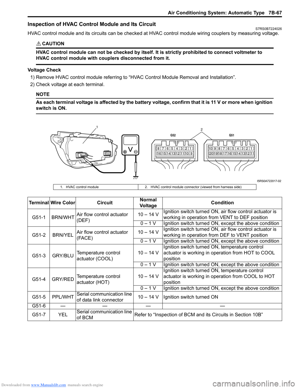
Inspection of HVAC Control Module and Its CircuitS7RS0B7224026
HVAC control module and its circuits can be checked at HVAC control module wiring couplers by measuring voltage.
CAUTION!
HVAC control module can not be checked by itself. It is strictly prohibited to connect voltmeter to
HVAC control module with couplers disconnected from it.
Voltage Check
1) Remove HVAC control module referring to “HVAC Control Module Removal and Installation”.
2) Check voltage at each terminal.
NOTE
As each terminal voltage is affected by the battery voltage, confirm that it is 11 V or more when ignition
switch is ON.
7812910
65 431516 14 13 12 11
G52
789101920121112
65 431718 16 15 14 13
G51
1
2
I5RS0A722017-02
1. HVAC control module2. HVAC control module connector (viewed from harness side)
Terminal Wire Color CircuitNormal
Vo l ta g e Condition
G51-1 BRN/WHT Air flow control actuator
(DEF) 10 – 14 V
Ignition switch turned ON, ai
r flow control actuator is
working in operation fr om VENT to DEF position
0 – 1 V Ignition switch turned ON, except the above condition
G51-2 BRN/YEL Air flow control actuator
(FACE) 10 – 14 V
Ignition switch turned ON, ai
r flow control actuator is
working in operation fr om DEF to VENT position
0 – 1 V Ignition switch turned ON, except the above condition
G51-3 GRY/BLU Temperature control
actuator (COOL) 10 – 14 VIgnition switch turned ON, temperature control
actuator is working in ope
ration from HOT to COOL
position
0 – 1 V Ignition switch turned ON, except the above condition
G51-4 GRY/RED Temperature control
actuator (HOT) 10 – 14 VIgnition switch turned ON, temperature control
actuator is working in operation from COOL to HOT
position
0 – 1 V Ignition switch turned ON, except the above condition
G51-5 PPL/WHT Serial communication line
of data link connector 10 – 14 V Ignition switch turned ON
G51-6 — — — —
G51-7 YEL Serial communication line
of BCM Refer to “Inspection of BCM a
nd its Circuits in Section 10B”
Page 1050 of 1496

Downloaded from www.Manualslib.com manuals search engine 8B-12 Air Bag System:
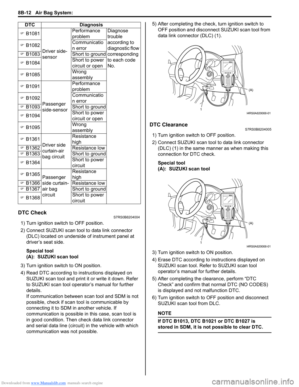
DTC CheckS7RS0B8204004
1) Turn ignition switch to OFF position.
2) Connect SUZUKI scan tool to data link connector (DLC) located on underside of instrument panel at
driver’s seat side.
Special tool
(A): SUZUKI scan tool
3) Turn ignition switch to ON position.
4) Read DTC according to instructions displayed on SUZUKI scan tool and print it or write it down. Refer
to SUZUKI scan tool operator’s manual for further
details.
If communication between scan tool and SDM is not
possible, check if scan tool is communicable by
connecting it to SDM in another vehicle. If
communication is possible in this case, scan tool is
in good condition. Then check data link connector
and serial data line (circuit) in the vehicle with which
communication was not possible. 5) After completing the check,
turn ignition switch to
OFF position and disconnect SUZUKI scan tool from
data link connector (DLC) (1).
DTC ClearanceS7RS0B8204005
1) Turn ignition switch to OFF position.
2) Connect SUZUKI scan tool to data link connector (DLC) (1) in the same manner as when making this
connection for DTC check.
Special tool
(A): SUZUKI scan tool
3) Turn ignition switch to ON position.
4) Erase DTC according to instructions displayed on
SUZUKI scan tool. Refer to SUZUKI scan tool
operator’s manual for further details.
5) After completing the clearance, perform “DTC Check” and confirm that normal DTC (NO CODES)
is displayed and not malfunction DTC.
6) Turn ignition switch to OFF position and disconnect SUZUKI scan tool from DLC.
NOTE
If DTC B1013, DTC B1 021 or DTC B1027 is
stored in SDM, it is not possible to clear DTC.
�) B1081
Driver side-
sensor Performance
problem
Diagnose
trouble
according to
diagnostic flow
corresponding
to each code
No.
�)
B1082 Communicatio
n error
�) B1083 Short to ground
�) B1084 Short to power
circuit or open
�) B1085 Wrong
assembly
�) B1091
Passenger
side-sensor Performance
problem
�) B1092 Communicatio
n error
�) B1093 Short to ground
�) B1094 Short to power
circuit or open
�) B1095 Wrong
assembly
�) B1361
Driver side
curtain-air
bag circuit Resistance
high
�) B1362 Resistance low
�) B1363 Short to ground
�) B1364 Short to power
circuit
�) B1365
Passenger
side curtain-
air bag
circuit Resistance
high
�) B1366 Resistance low
�) B1367 Short to ground
�) B1368 Short to power
circuit
DTC Diagnosis
1
(A)I4RS0A820008-01
1(A)I4RS0A820008-01