2008 SUZUKI SWIFT rpm data
[x] Cancel search: rpm dataPage 669 of 1496

Downloaded from www.Manualslib.com manuals search engine Automatic Transmission/Transaxle: 5A-25
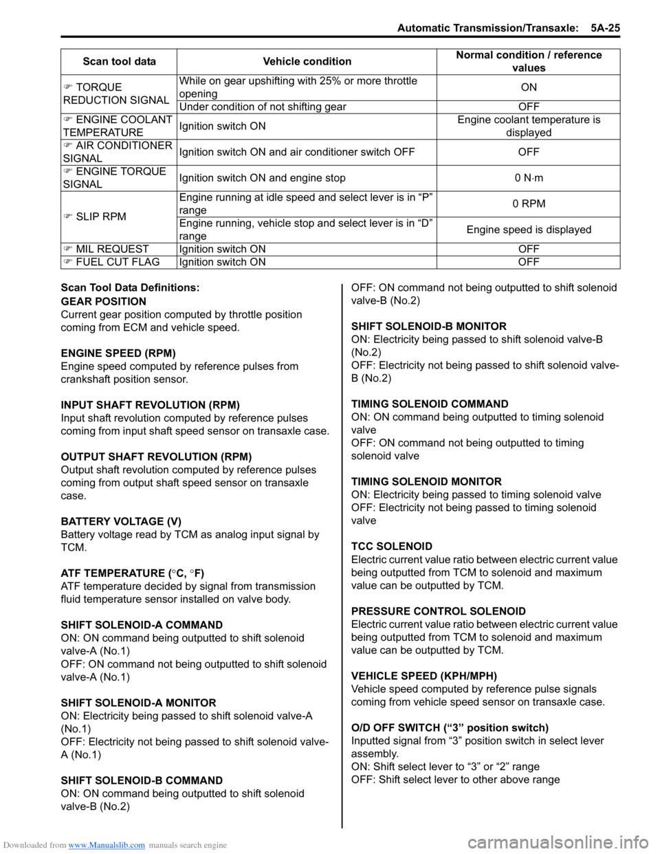
Scan Tool Data Definitions:
GEAR POSITION
Current gear position computed by throttle position
coming from ECM and vehicle speed.
ENGINE SPEED (RPM)
Engine speed computed by reference pulses from
crankshaft position sensor.
INPUT SHAFT REVOLUTION (RPM)
Input shaft revolution computed by reference pulses
coming from input shaft speed sensor on transaxle case.
OUTPUT SHAFT REVOLUTION (RPM)
Output shaft revolution computed by reference pulses
coming from output shaft speed sensor on transaxle
case.
BATTERY VOLTAGE (V)
Battery voltage read by TCM as analog input signal by
TCM.
ATF TEMPERATURE (°C, °F)
ATF temperature decided by signal from transmission
fluid temperature sensor installed on valve body.
SHIFT SOLENOID-A COMMAND
ON: ON command being outputted to shift solenoid
valve-A (No.1)
OFF: ON command not being outputted to shift solenoid
valve-A (No.1)
SHIFT SOLENOID-A MONITOR
ON: Electricity being passed to shift solenoid valve-A
(No.1)
OFF: Electricity not being passed to shift solenoid valve-
A (No.1)
SHIFT SOLENOID-B COMMAND
ON: ON command being outputted to shift solenoid
valve-B (No.2) OFF: ON command not being outputted to shift solenoid
valve-B (No.2)
SHIFT SOLENOID-B MONITOR
ON: Electricity being passed to shift solenoid valve-B
(No.2)
OFF: Electricity not being passed to shift solenoid valve-
B (No.2)
TIMING SOLENOID COMMAND
ON: ON command being outputted to timing solenoid
valve
OFF: ON command not being outputted to timing
solenoid valve
TIMING SOLENOID MONITOR
ON: Electricity being passed to timing solenoid valve
OFF: Electricity not being passed to timing solenoid
valve
TCC SOLENOID
Electric current value ratio between electric current value
being outputted from TCM to solenoid and maximum
value can be outputted by TCM.
PRESSURE CONTROL SOLENOID
Electric current value ratio between electric current value
being outputted from TCM to solenoid and maximum
value can be outputted by TCM.
VEHICLE SPEED (KPH/MPH)
Vehicle speed computed by reference pulse signals
coming from vehicle speed sensor on transaxle case.
O/D OFF SWITCH (“3” position switch)
Inputted signal from “3” position switch in select lever
assembly.
ON: Shift select lever to “3” or “2” range
OFF: Shift select lever to other above range
�)
TORQUE
REDUCTION SIGNAL While on gear upshifting with 25% or more throttle
opening
ON
Under condition of not shifting gear OFF
�) ENGINE COOLANT
TEMPERATURE Ignition switch ON Engine coolant temperature is
displayed
�) AIR CONDITIONER
SIGNAL Ignition switch ON and air conditioner switch OFF OFF
�) ENGINE TORQUE
SIGNAL Ignition switch ON and engine stop 0 N
⋅m
�) SLIP RPM Engine running at idle speed
and select lever is in “P”
range 0 RPM
Engine running, vehicle stop and select lever is in “D”
range Engine speed is displayed
�) MIL REQUEST Ignition switch ON OFF
�) FUEL CUT FLAG Ignition switch ON OFFScan tool data Vehicle condition
Normal condition / reference
values
Page 893 of 1496

Downloaded from www.Manualslib.com manuals search engine Power Assisted Steering System: 6C-11
Scan Tool DataS7RS0B6304006
NOTE
When P/S motor is cold condition (that is, armature coil of P/S motor is not heated), normal value with
asterisk (*) mark in the following table is displayed on scan tool.
�) C1143 P/S motor circuit current too
high Measured motor drive current is
more than 50 A.
• P/S motor circuit
• P/S motor
• P/S control module1 driving
cycle
�) C1145 P/S motor circuit current too
low Measured motor drive current is
less than 2 A continuously for
more than 3 seconds even though
target motor drive current is more
than 4 A.
or
Measured motor drive current is
less than 0.8 A for total 1 second
even though motor control duty is
more than 90% while target motor
drive current is less than 8 A. 1 driving
cycle
�) C1153 P/S control module power
supply circuit Power supply voltage of P/S
control module is less than 9 V for
5 seconds continuously. • P/S control module power
supply circuit
• Undercharged Battery
• P/S control module 1 driving
cycle
�) C1155 P/S control module internal
failure Internal memory (EEPROM) is
data error.
• P/S control moduleNot
applicable
Internal circuit is faulty.
or
Power supply voltage of P/S
control module exceeded 17.5 V. • Overcharged Battery
• P/S control module
1 driving
cycle
DTC No. Detecting item
Detecting condition
(DTC will set when detecting) Trouble area MIL
Scan tool data
Vehicle conditionNormal condition
�) Battery Voltage
Ignition switch ON 10 – 14 V
�) TQS Power Supply 10 – 14 V
�) TQS Main Torque Engine running at idle speed Steering wheel at fully turned to left –9.4 – 0 N
⋅m
Steering wheel at free 0 N⋅m
Steering wheel at fully turned to right 0 – 9.4 N ⋅m
�) TQS Sub Torque Engine running at idle speed Steering wheel at fully turned to left –9.4 – 0 N
⋅m
Steering wheel at free 0 N⋅m
Steering wheel at fully turned to right 0 – 9.4 N ⋅m
�) Assist Torque Engine running at idle speed Steering wheel at fully turned to left –9.4 – 0 N
⋅m
Steering wheel at free 0 N⋅m
Steering wheel at fully turned to right 0 – 9.4 N ⋅m
�) Motor Control Engine running at idle speed Steering wheel at free
0 A
Steering wheel at fully turned to left or right *35 – 45 A
�) Motor Monitor Engine running at idle speed Steering wheel at free
0 A
Steering wheel at fully turned to left or right *35 – 45 A
�) Vehicle Speed Engine running and vehicle at stop 0 km/h
�) Engine Speed Engine running at idle speed after warming up 700 ± 50 rpm
�) Motor Volt Engine running at idle speed Steering wheel at free
0.8 – 1 V
Steering wheel at fully turned to right About 5 V
�) Ignition switch Ignition switch ON ON
Page 894 of 1496

Downloaded from www.Manualslib.com manuals search engine 6C-12 Power Assisted Steering System:
Scan Tool Data Definitions
Battery Voltage
This parameter indicates battery positive voltage.
TQS Power Supply (Torque Sensor Power Supply, V)
This parameter indicates the power supply voltage which
the P/S control module supplies to the torque sensor.
TQS Main Torque (Torque Sensor Main Torque, N ⋅m)
The torque sensor is installed to detect the steering force
and the steering directio n. It consists of two
potentiometers and the main torque sensor is one of
these.
TQS Sub Torque (Torque Sensor Sub Torque, N ⋅m)
The torque sensor is installed to detect the steering force
and the steering directio n. It consists of two
potentiometers and the sub-torque sensor is one of
these. Its output characteristics are compared with those
of the main torque sensor.
Assist Torque (N ⋅m)
This parameter is an internal parameter of the P/S
control module. It is obtained by computing the torque
sensor input signal. Motor Control (Motor Control Current, A)
Based on the input signal, the P/S control module
determines the assist amount
and controls the current to
the motor suitable for that a ssist amount. This parameter
indicates that control value.
Motor Monitor (Motor Monitor Current, A)
This parameter indicates the actually measured value of
the current flowing to the motor. The motor circuit
condition is diagnosed by co mparing this parameter with
“Motor Control” parameter described previously.
Vehicle Speed (km/h, MPH)
Vehicle speed signal is fed from BCM. P/S control
module determines the amount of power assist based on
this vehicle speed signal and the torque sensor signal.
Engine Speed (rpm)
Engine speed signal is fed from the ECM so that it can
be used for trouble diagnos is of the electric power
steering system.
Motor Volt (V)
This parameter indicates the voltage between motor
terminals.
Ignition switch (ON, OFF)
This parameter indicates the condition of the power
supply through the ignition switch.
Visual InspectionS7RS0B6304007
Visually check the following pats and system.
P/S System Symptom DiagnosisS7RS0B6304008
This section describes trouble diagnosis of the P/S system parts whose trouble is not indicated by the on-board
diagnostic system (self-diagnostic functi on). When no malfunction is indicated by the on-board diagnostic system
(self-diagnosis function) and those stee ring basic parts as described in “Steering Symptom Diagnosis in Section 6A”
are all in good condition, check the following power steer ing system parts which may be a possible cause for each
symptom of the steering. Inspection Item Referring section
Battery Level, leakage, color “Batte ry Description in Section 1J”
Connectors of electric wire
harness Disconnection friction “Intermittent and Poor
Connection Inspection in Section 00”
Fuses Burning “Cautions in Body Electric al System Servicing in Section 9A”
Parts Installation, damage
Other parts that can be checked visually
Condition Possible cause Correction / Reference Item
Steering wheel feels
heavy (Perform “Steering
Force Check” before
diagnosis.) Steering wheel installed improperly
(twisted)
Install steering wheel correctly.
Poor performance of torque sensor Check torque sensor referring to “Torque
Sensor and Its Circuit Inspection”.
Poor performance of P/S motor Check motor referring to “P/S Motor and Its
Circuit Inspection”.
Steering gear case assembly faulty Replace.
Poor performance of vehicle speed
signal from ECM Check vehicle speed signal circuit referring to
“DTC C1121 / C1123 / C1124: VSS Circuit
Failure”.
Page 915 of 1496

Downloaded from www.Manualslib.com manuals search engine Power Assisted Steering System: 6C-33
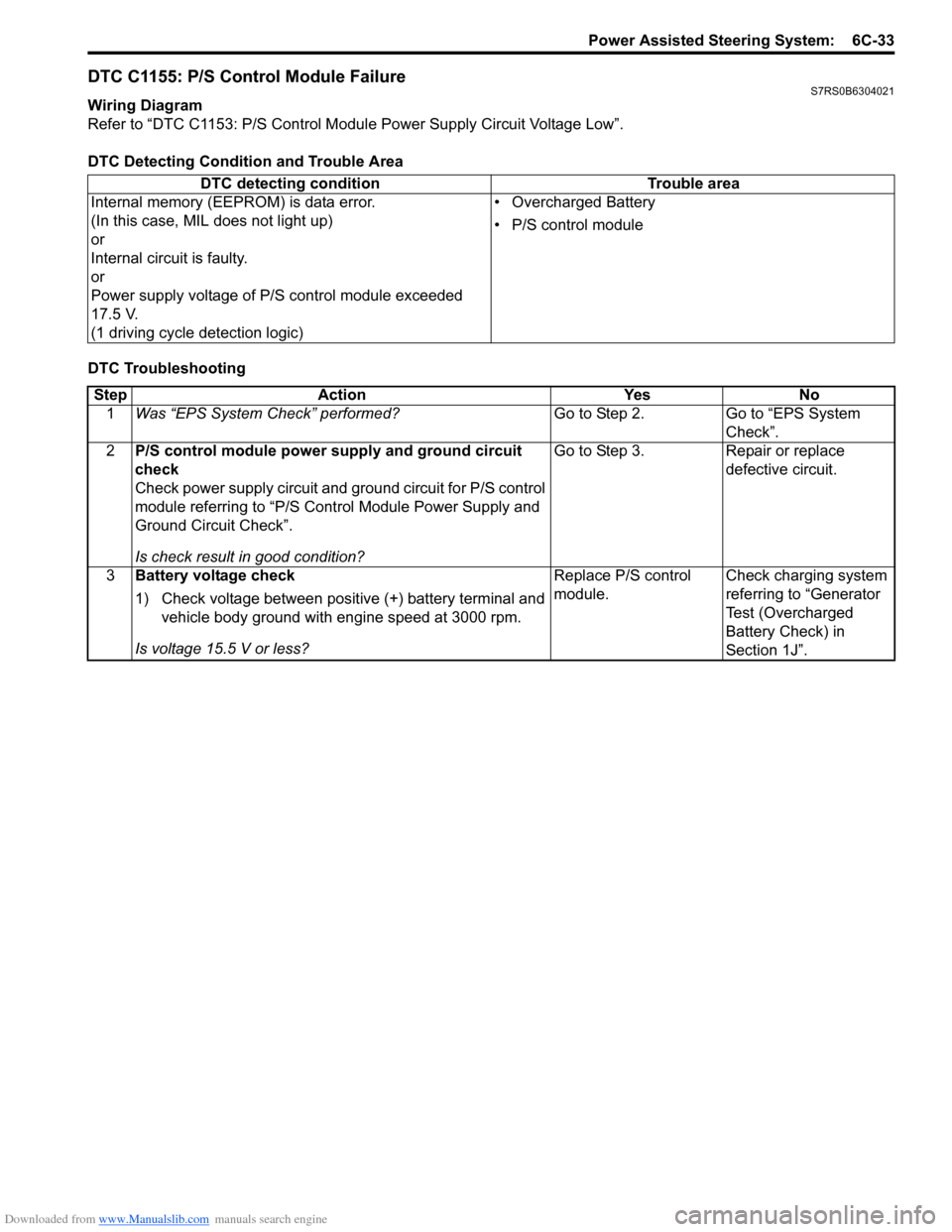
DTC C1155: P/S Control Module FailureS7RS0B6304021
Wiring Diagram
Refer to “DTC C1153: P/S Control Module Power Supply Circuit Voltage Low”.
DTC Detecting Condition and Trouble Area
DTC Troubleshooting DTC detecting condition Trouble area
Internal memory (EEPROM) is data error.
(In this case, MIL does not light up)
or
Internal circuit is faulty.
or
Power supply voltage of P/S control module exceeded
17.5 V.
(1 driving cycle detection logic) • Overcharged Battery
• P/S control module
Step
Action YesNo
1 Was “EPS System Check” performed? Go to Step 2.Go to “EPS System
Check”.
2 P/S control module power supply and ground circuit
check
Check power supply circuit and ground circuit for P/S control
module referring to “P/S Control Module Power Supply and
Ground Circuit Check”.
Is check result in good condition? Go to Step 3.
Repair or replace
defective circuit.
3 Battery voltage check
1) Check voltage between positive (+) battery terminal and
vehicle body ground with engine speed at 3000 rpm.
Is voltage 15.5 V or less? Replace P/S control
module.
Check charging system
referring to “Generator
Test (Overcharged
Battery Check) in
Section 1J”.
Page 1415 of 1496

Downloaded from www.Manualslib.com manuals search engine Body Electrical Control System: 10B-12
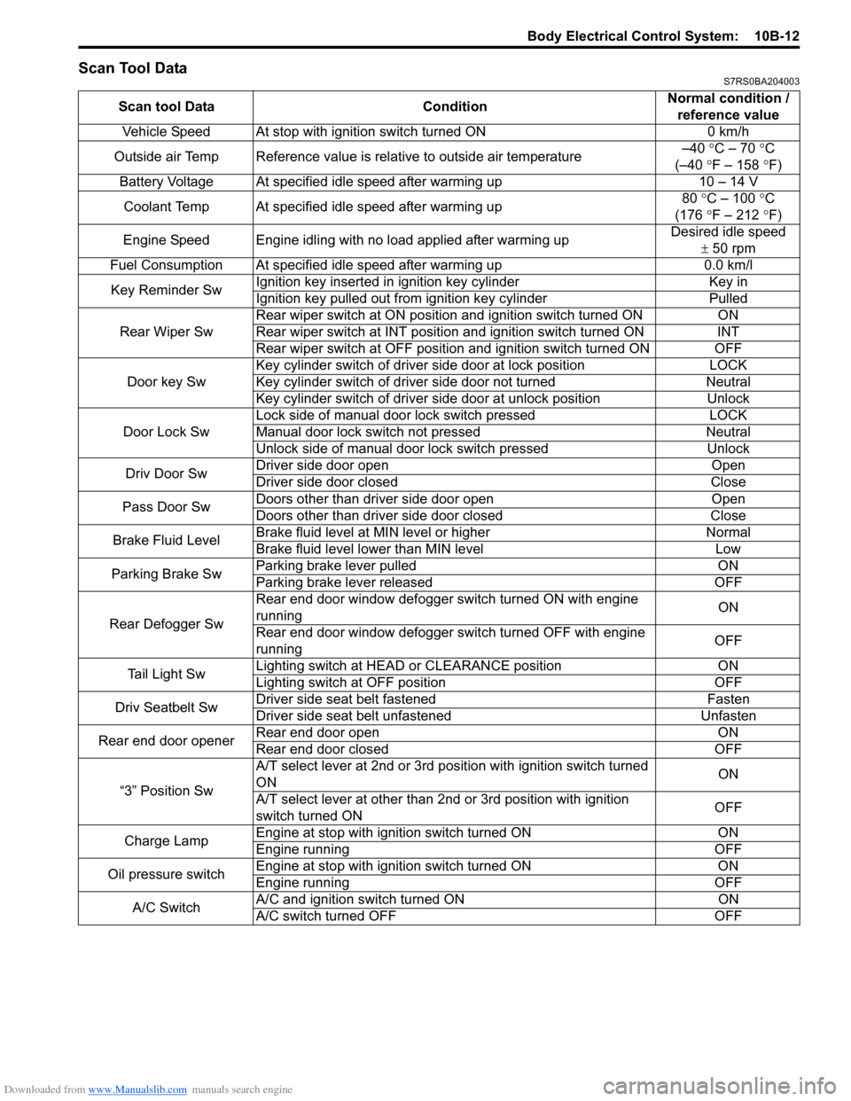
Scan Tool DataS7RS0BA204003
Scan tool DataConditionNormal condition /
reference value
Vehicle Speed At stop with ignition switch turned ON 0 km/h
Outside air Temp Reference value is relative to outside air temperature –40
°C – 70 °C
(–40 °F – 158 ° F)
Battery Voltage At specified idle speed after warming up 10 – 14 V
Coolant Temp At specified idle speed after warming up 80
°C – 100 ° C
(176 °F – 212 ° F)
Engine Speed Engine idling with no load applied after warming up Desired idle speed
± 50 rpm
Fuel Consumption At specified idle speed after warming up 0.0 km/l
Key Reminder Sw Ignition key inserted in
ignition key cylinder Key in
Ignition key pulled out from ignition key cylinder Pulled
Rear Wiper Sw Rear wiper switch at ON position and ignition switch turned ON
ON
Rear wiper switch at INT position and ignition switch turned ON INT
Rear wiper switch at OFF position and ignition switch turned ON OFF
Door key Sw Key cylinder switch of driver side door at lock position
LOCK
Key cylinder switch of driver side door not turned Neutral
Key cylinder switch of driver side door at unlock position Unlock
Door Lock Sw Lock side of manual door lock switch pressed
LOCK
Manual door lock switch not pressed Neutral
Unlock side of manual door lock switch pressed Unlock
Driv Door Sw Driver side door open
Open
Driver side door closed Close
Pass Door Sw Doors other than driver side door open
Open
Doors other than driver side door closed Close
Brake Fluid Level Brake fluid level at MIN level or higher
Normal
Brake fluid level lower than MIN level Low
Parking Brake Sw Parking brake lever pulled
ON
Parking brake lever released OFF
Rear Defogger Sw Rear end door window defogger switch turned ON with engine
running
ON
Rear end door window defogger switch turned OFF with engine
running OFF
Tail Light Sw Lighting switch at HEAD
or CLEARANCE position ON
Lighting switch at OFF position OFF
Driv Seatbelt Sw Driver side seat belt fastened
Fasten
Driver side seat belt unfastened Unfasten
Rear end door opener Rear end door open
ON
Rear end door closed OFF
“3” Position Sw A/T select lever at 2nd or 3rd position with ignition switch turned
ON
ON
A/T select lever at other than 2nd or 3rd position with ignition
switch turned ON OFF
Charge Lamp Engine at stop with ignition switch turned ON
ON
Engine running OFF
Oil pressure switch Engine at stop with ignition switch turned ON
ON
Engine running OFF
A/C Switch A/C and ignition switch turned ON
ON
A/C switch turned OFF OFF
Page 1416 of 1496

Downloaded from www.Manualslib.com manuals search engine 10B-13 Body Electrical Control System:
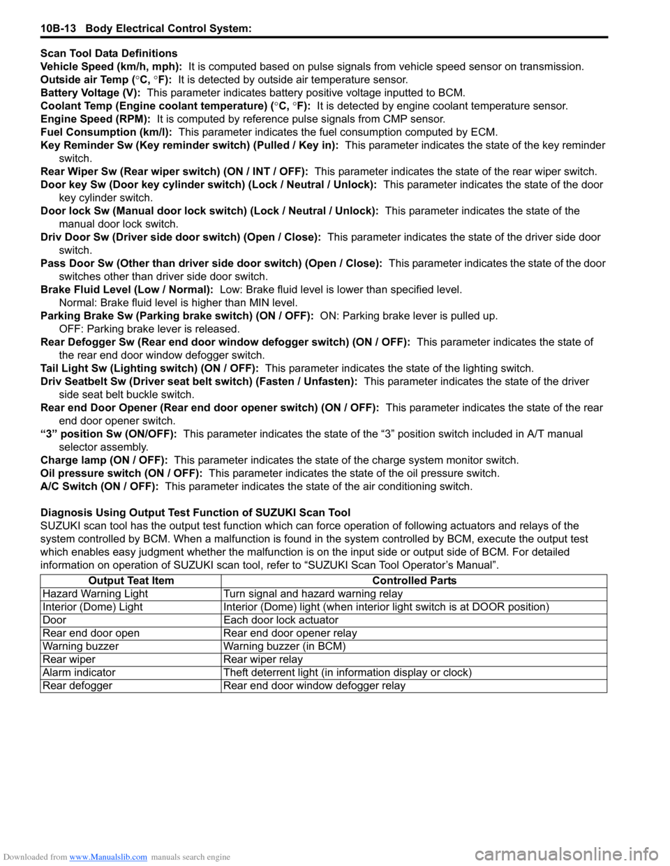
Scan Tool Data Definitions
Vehicle Speed (km/h, mph): It is computed based on pulse signals from vehicle speed sensor on transmission.
Outside air Temp ( °C, °F): It is detected by outside air temperature sensor.
Battery Voltage (V): This parameter indicates battery po sitive voltage inputted to BCM.
Coolant Temp (Engine coolant temperature) ( °C, °F): It is detected by engine coolant temperature sensor.
Engine Speed (RPM): It is computed by reference pulse signals from CMP sensor.
Fuel Consumption (km/l): This parameter indicates the fuel consumption computed by ECM.
Key Reminder Sw (Key reminder switch) (Pulled / Key in): This parameter indicates the state of the key reminder
switch.
Rear Wiper Sw (Rear wiper switch) (ON / INT / OFF): This parameter indicates the state of the rear wiper switch.
Door key Sw (Door key cylinder switch) (Lock / Neutral / Unlock): This parameter indicates the state of the door
key cylinder switch.
Door lock Sw (Manual door lock switch) (Lock / Neutral / Unlock): This parameter indicates the state of the
manual door lock switch.
Driv Door Sw (Driver side d oor switch) (Open / Close): This parameter indicates the state of the driver side door
switch.
Pass Door Sw (Other than driver side door switch) (Open / Close): This parameter indicates the state of the door
switches other than driver side door switch.
Brake Fluid Level (Low / Normal): Low: Brake fluid level is lower than specified level.
Normal: Brake fluid level is higher than MIN level.
Parking Brake Sw (Parking brake switch) (ON / OFF): ON: Parking brake lever is pulled up.
OFF: Parking brake lever is released.
Rear Defogger Sw (Rear end door window defogger switch) (ON / OFF): This parameter indicates the state of
the rear end door window defogger switch.
Tail Light Sw (Lighting switch) (ON / OFF): This parameter indicates the state of the lighting switch.
Driv Seatbelt Sw (Driver seat belt switch) (Fasten / Unfasten): This parameter indicates the state of the driver
side seat belt buckle switch.
Rear end Door Opener (Rear end door opener switch) (ON / OFF): This parameter indicates the state of the rear
end door opener switch.
“3” position Sw (ON/OFF): This parameter indicates the state of the “3 ” position switch included in A/T manual
selector assembly.
Charge lamp (ON / OFF): This parameter indicates the state of the charge system monitor switch.
Oil pressure switch (ON / OFF): This parameter indicates the state of the oil pressure switch.
A/C Switch (ON / OFF): This parameter indicates the state of the air conditioning switch.
Diagnosis Using Output Test Function of SUZUKI Scan Tool
SUZUKI scan tool has the output test function which can force operation of following actuators and relays of the
system controlled by BCM. When a malf unction is found in the system controlled by BCM, execute the output test
which enables easy judgment whether the malfunction is on the input side or output side of BCM. For detailed
information on operation of SUZUKI scan tool, refer to “SUZUKI Scan Tool Operator’s Manual”.
Output Teat Item Controlled Parts
Hazard Warning Light Turn signal and hazard warning relay
Interior (Dome) Light Interior (Dome) light (wh en interior light switch is at DOOR position)
Door Each door lock actuator
Rear end door open Rear end door opener relay
Warning buzzer Warning buzzer (in BCM)
Rear wiper Rear wiper relay
Alarm indicator Theft deterrent light (in information display or clock)
Rear defogger Rear end door window defogger relay