2008 SUZUKI SWIFT replace engine mount
[x] Cancel search: replace engine mountPage 308 of 1496

Downloaded from www.Manualslib.com manuals search engine 1D-23 Engine Mechanical:
8) Install new O-ring (1) to oil gallery pipes No.2 (2) and
No.3 (3).
9) Install oil gallery pipes No.2 and No.3 to cylinder
head (4) and timing chain cover (5).
Tighten bolts to specified torque.
Tightening torque
Oil gallery pipe No.2 and No.3 bolt (a): 11 N·m (
1.1 kgf-m, 8.0 lb-ft)
10) Install water pump pulley. 11) Install cylinder head cover referring to “Cylinder Head Cover Removal and Installation”.
12) Install oil pan referring to “Oil Pan and Oil Pump
Strainer Removal and Installation in Section 1E”.
13) Install crankshaft pulley (1). Tighten bolt (2) to specified torque. To lock crankshaft pulley, use
special tool with it as shown in figure.
Special tool
(A): 09917–68221
Tightening torque
Crankshaft pulley bolt (a): 150 N·m (15.0 kgf-m,
108.5 lb-ft)
14) Install engine assembly to vehicle referring to “Engine Assembly Removal and Installation”.
Timing Chain Cover InspectionS7RS0B1406014
Oil Seal
Check oil seal lip for fault or other damage. Replace as
necessary. Timing Chain Cover
Inspect strainer (1) of oil passage for driving intake cam
timing sprocket assembly (VVT actuator).
If clog or foreign matter exists, clean strainer.
Oil Control Valve Removal and InstallationS7RS0B1406015
Removal
Remove oil gallery pipe No.1
(1) and oil control valve (2)
from timing chain cover (3).
Installation
1) Install new O-ring (4) to oil control valve.
2) Install oil control valve to timing chain cover. Tighten nuts to specification.
Tightening torque
Oil control valve mounting nut (a): 11 N·m (1.1
kgf-m, 8.0 lb-ft)
3) Install oil gallery pipe No .1 with new copper washers
(5) to timing chain cover.
Tighten bolts to specification.
Tightening torque
Oil gallery pipe No.1 bolt (b): 30 N·m (3.0 kgf-m,
21.5 lb-ft)
(a)
(a) 1
2
3
4
5
I3RH0B140027-01
I2RH0B140056-01
1
I3RH0B140028-01
1
5
(b) 3
(a)
2 4
5
I3RM0A140027-01
Page 309 of 1496

Downloaded from www.Manualslib.com manuals search engine Engine Mechanical: 1D-24
Oil Control Valve InspectionS7RS0B1406016
Oil Control Valve1) Inspect strainer (1) and mating surface (2) of oil control valve for clog or damage. Clean oil control
valve if clog or foreign matter is present on strainer
or mating surface of oil control valve.
Replace oil control valve if its mating surface is
damaged.
2) Check resistance between terminals of oil control
valve.
Oil control valve resistance
6.7 – 7.7 Ω (at 20 °C (68 °F)) Oil Gallery Pipe
Inspect oil gallery pipes No
.1, No.2 (2) and No.3 (3).
Replace if crack, deformation or clog exists.
Timing Chain and Chain Tensioner ComponentsS7RS0B1406017
1
2
I3RM0A140028-01
1
3
2
I3RH0B140030-01
I4RS0A140012-04
1. Crankshaft timing sprocket 5. Timing chain tensioner adjuster assembly 9. Spacer
2. Timing chain : Apply engine oil. 6. Chain tensioner adjuster mounting bolt
: 25 N⋅m (2.5 kgf-m, 18.0 lb-ft)
3. Timing chain No.1 guide : Apply engine oil to sliding surface. 7. Timing chain tensioner bolt
: 11 N⋅m (1.1 kgf-m, 8.0 lb-ft)
4. Timing chain tensioner : Apply engine oil to sliding surface. 8. Timing chain No.1 guide bolt
: 9 N⋅m (0.9 kgf-m, 6.5 lb-ft)
Page 334 of 1496

Downloaded from www.Manualslib.com manuals search engine 1D-49 Engine Mechanical:
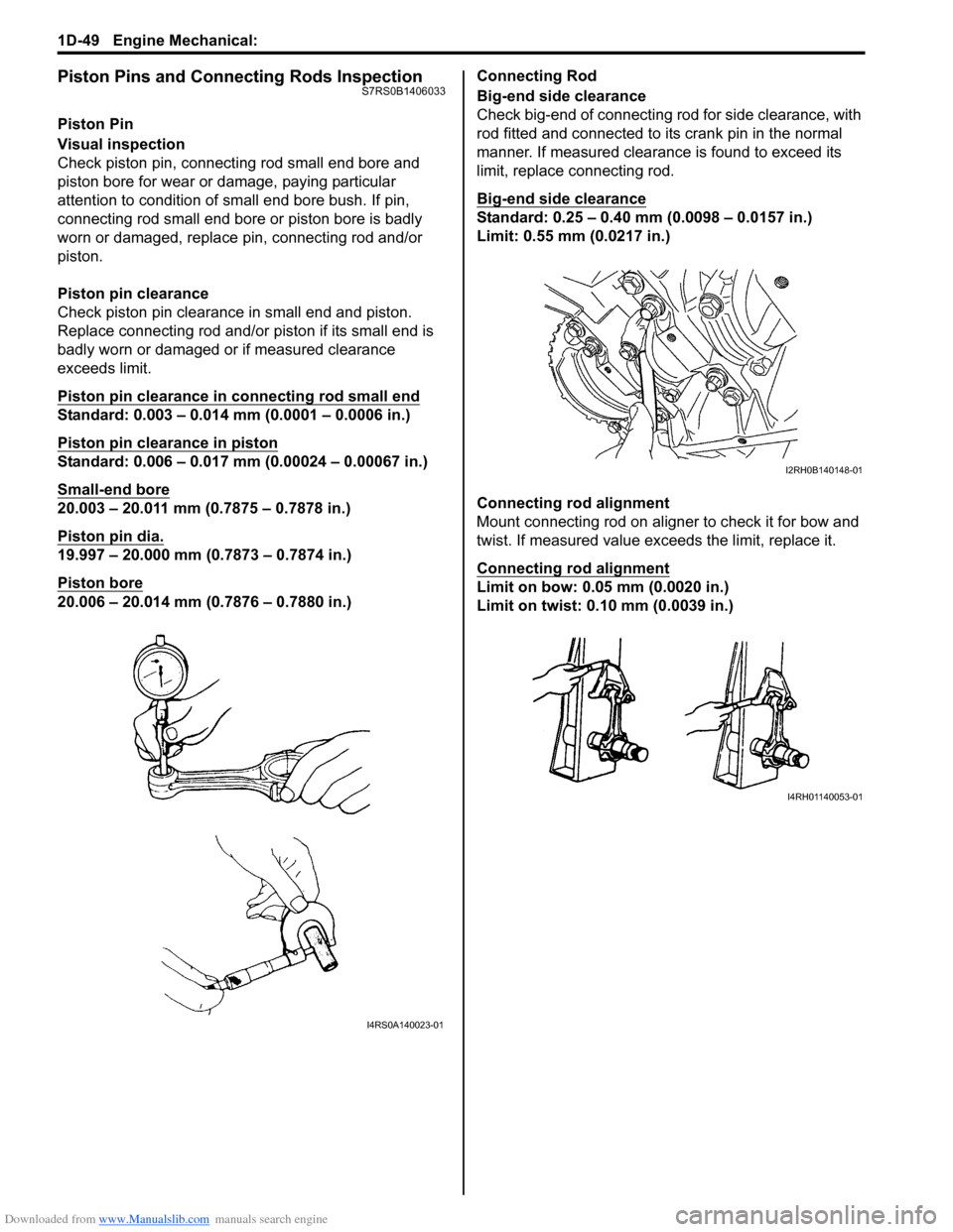
Piston Pins and Connecting Rods InspectionS7RS0B1406033
Piston Pin
Visual inspection
Check piston pin, connecting rod small end bore and
piston bore for wear or damage, paying particular
attention to condition of small end bore bush. If pin,
connecting rod small end bore or piston bore is badly
worn or damaged, replace pin, connecting rod and/or
piston.
Piston pin clearance
Check piston pin clearance in small end and piston.
Replace connecting rod and/or piston if its small end is
badly worn or damaged or if measured clearance
exceeds limit.
Piston pin clearance in connecting rod small end
Standard: 0.003 – 0.014 mm (0.0001 – 0.0006 in.)
Piston pin clearance in piston
Standard: 0.006 – 0.017 mm (0.00024 – 0.00067 in.)
Small-end bore
20.003 – 20.011 mm (0.7875 – 0.7878 in.)
Piston pin dia.
19.997 – 20.000 mm (0.7873 – 0.7874 in.)
Piston bore
20.006 – 20.014 mm (0.7876 – 0.7880 in.)Connecting Rod
Big-end side clearance
Check big-end of connecting rod for side clearance, with
rod fitted and connected to its crank pin in the normal
manner. If measured clearance is found to exceed its
limit, replace connecting rod.
Big-end side clearance
Standard: 0.25 – 0.40 mm (0.0098 – 0.0157 in.)
Limit: 0.55 mm (0.0217 in.)
Connecting rod alignment
Mount connecting rod on aligner to check it for bow and
twist. If measured value exceeds the limit, replace it.
Connecting rod alignment
Limit on bow: 0.05 mm (0.0020 in.)
Limit on twist: 0.10 mm (0.0039 in.)
I4RS0A140023-01
I2RH0B140148-01
I4RH01140053-01
Page 335 of 1496

Downloaded from www.Manualslib.com manuals search engine Engine Mechanical: 1D-50
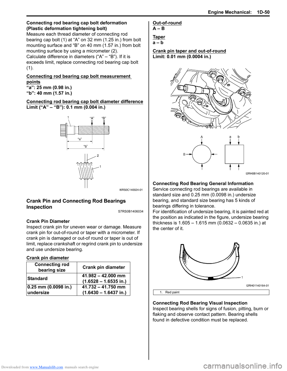
Connecting rod bearing cap bolt deformation
(Plastic deformation tightening bolt)
Measure each thread diameter of connecting rod
bearing cap bolt (1) at “A” on 32 mm (1.25 in.) from bolt
mounting surface and “B” on 40 mm (1.57 in.) from bolt
mounting surface by using a micrometer (2).
Calculate difference in diameters (“A” – “B”). If it is
exceeds limit, replace connecting rod bearing cap bolt
(1).
Connecting rod bearing cap bolt measurement
points
“a”: 25 mm (0.98 in.)
“b”: 40 mm (1.57 in.)
Connecting rod bearing cap bolt diameter difference
Limit (“A” – “B”): 0.1 mm (0.004 in.)
Crank Pin and Connecting Rod Bearings
Inspection
S7RS0B1406034
Crank Pin Diameter
Inspect crank pin for uneven wear or damage. Measure
crank pin for out-of-round or taper with a micrometer. If
crank pin is damaged or out-of round or taper is out of
limit, replace crankshaft or regrind crank pin to undersize
and use undersize bearing.
Crank pin diameter
Out-of-round
A – B
Ta p e r
a – b
Crank pin taper and out-of-round
Limit: 0.01 mm (0.0004 in.)
Connecting Rod Bearing General Information
Service connecting rod be arings are available in
standard size and 0.25 mm (0.0098 in.) undersize
bearing, and standard size bearing has 5 kinds of
bearings differing in tolerance.
For identification of undersize bearing, it is painted red at
the position as indicated in the figure, undersize bearing
thickness is 1.605 – 1.615 mm (0.0632 – 0.0635 in.) at
the center of it.
Connecting Rod Bearing Visual Inspection
Inspect bearing shells for signs of fusion, pitting, burn or
flaking and observe contact pattern. Bearing shells
found in defective condition must be replaced.
Connecting rod
bearing size Crank pin diameter
Standard 41.982 – 42.000 mm
(1.6528 – 1.6535 in.)
0.25 mm (0.0098 in.)
undersize 41.732 – 41.750 mm
(1.6430 – 1.6437 in.)
I6RS0C140024-01
1. Red paint
I2RH0B140120-01
I2RH01140164-01
Page 343 of 1496

Downloaded from www.Manualslib.com manuals search engine Engine Mechanical: 1D-58
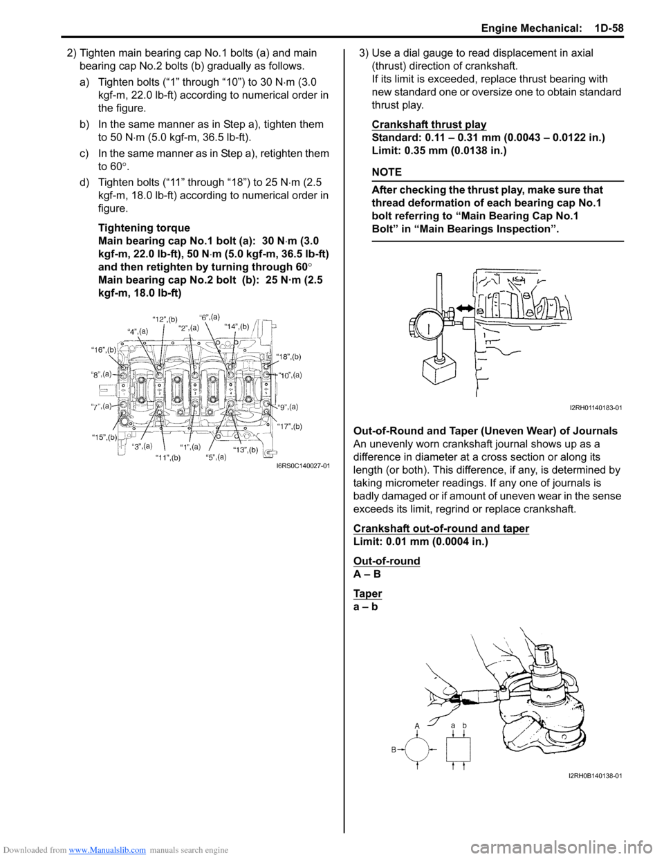
2) Tighten main bearing cap No.1 bolts (a) and main bearing cap No.2 bolts (b ) gradually as follows.
a) Tighten bolts (“1” through “10”) to 30 N ⋅m (3.0
kgf-m, 22.0 lb-ft) according to numerical order in
the figure.
b) In the same manner as in Step a), tighten them to 50 N ⋅m (5.0 kgf-m, 36.5 lb-ft).
c) In the same manner as in Step a), retighten them to 60 °.
d) Tighten bolts (“11” through “18”) to 25 N ⋅m (2.5
kgf-m, 18.0 lb-ft) according to numerical order in
figure.
Tightening torque
Main bearing cap No.1 bolt (a): 30 N ⋅m (3.0
kgf-m, 22.0 lb-ft), 50 N ⋅m (5.0 kgf-m, 36.5 lb-ft)
and then retighten by turning through 60 °
Main bearing cap No.2 bolt (b): 25 N·m (2.5
kgf-m, 18.0 lb-ft) 3) Use a dial gauge to read displacement in axial
(thrust) direction of crankshaft.
If its limit is exceeded, replace thrust bearing with
new standard one or oversize one to obtain standard
thrust play.
Crankshaft thrust play
Standard: 0.11 – 0.31 mm (0.0043 – 0.0122 in.)
Limit: 0.35 mm (0.0138 in.)
NOTE
After checking the thrust play, make sure that
thread deformation of each bearing cap No.1
bolt referring to “Main Bearing Cap No.1
Bolt” in “Main Bear ings Inspection”.
Out-of-Round and Taper (Uneven Wear) of Journals
An unevenly worn crankshaft journal shows up as a
difference in diameter at a cross section or along its
length (or both). This difference, if any, is determined by
taking micrometer readings. If any one of journals is
badly damaged or if amount of uneven wear in the sense
exceeds its limit, regrind or replace crankshaft.
Crankshaft out-of-round and taper
Limit: 0.01 mm (0.0004 in.)
Out-of-round
A – B
Ta p e r
a – b
I6RS0C140027-01
I2RH01140183-01
I2RH0B140138-01
Page 367 of 1496

Downloaded from www.Manualslib.com manuals search engine Engine Cooling System: 1F-4
Diagnostic Information and Procedures
Engine Cooling Symptom DiagnosisS7RS0B1604001
ConditionPossible cause Correction / Reference Item
Engine overheats
(Radiator fan operates) Loose or broken water pump belt
Adjust or replace.
Not enough coolant Check coolant level and add as necessary.
Faulty thermostat Replace.
Faulty water pump Replace.
Dirty or bent radiator fins Clean or remedy.
Coolant leakage on cooling system Repair.
Clogged radiator Check and replace radiator as necessary.
Faulty radiator cap Replace.
Improper ignition timing Adjust.
Dragging brakes Adjust brake.
Slipping clutch Adjust or replace.
Poor charge battery Check and replace as necessary.
Poor generation generator Check and repair.
ECT sensor faulty Check and replace as necessary.
Radiator cooling fan relay No.2 and/or
No.3 faulty Check and replace as necessary.
Radiator fan motor faulty Check and replace as necessary.
ECM faulty Check and replace as necessary.
Wiring or grounding faulty Repair as necessary.
Equipped with too much electric load
part(s) Dismount.
Engine overheats
(Radiator fan does not
operate) Fuse blown
Check 30 A fuse of relay/fuse box and check
for short circuit to ground.
Radiator cooling fan relay No.1 faulty Check and replace as necessary.
ECT sensor faulty Check and replace as necessary.
Radiator cooling fan motor faulty Check and replace as necessary.
Wiring or grounding faulty Repair as necessary.
ECM faulty Check and replace as necessary.
Page 371 of 1496

Downloaded from www.Manualslib.com manuals search engine Engine Cooling System: 1F-8
Thermostat Removal and InstallationS7RS0B1606007
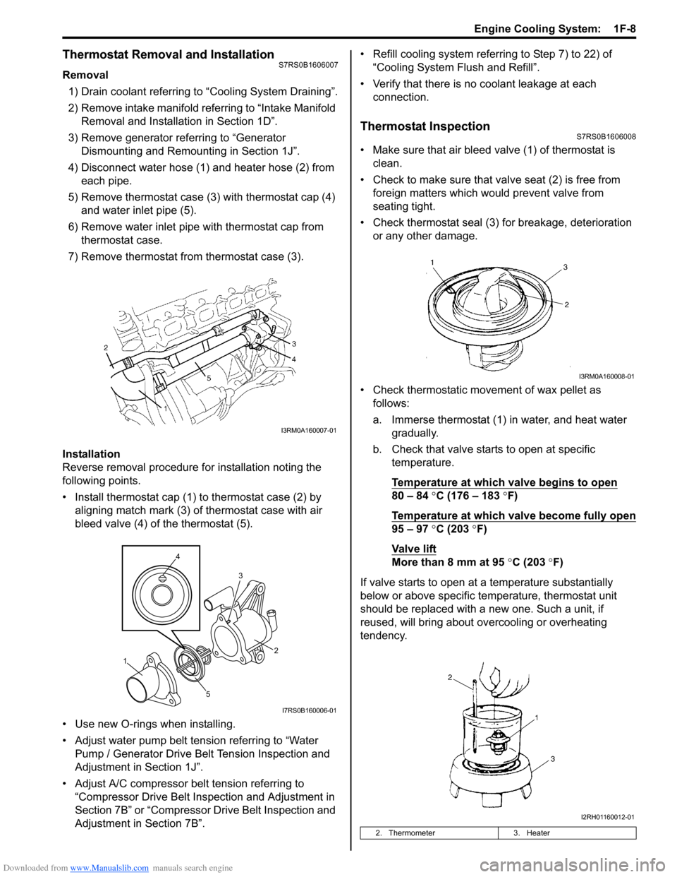
Removal1) Drain coolant referring to “Cooling System Draining”.
2) Remove intake manifold referring to “Intake Manifold Removal and Installa tion in Section 1D”.
3) Remove generator referring to “Generator Dismounting and Remounting in Section 1J”.
4) Disconnect water hose (1) and heater hose (2) from each pipe.
5) Remove thermostat case (3) with thermostat cap (4)
and water inlet pipe (5).
6) Remove water inlet pipe with thermostat cap from thermostat case.
7) Remove thermostat from thermostat case (3).
Installation
Reverse removal procedure for installation noting the
following points.
• Install thermostat cap (1) to thermostat case (2) by aligning match mark (3) of thermostat case with air
bleed valve (4) of the thermostat (5).
• Use new O-rings when installing.
• Adjust water pump belt tension referring to “Water Pump / Generator Drive Belt Tension Inspection and
Adjustment in Section 1J”.
• Adjust A/C compressor belt tension referring to “Compressor Drive Belt Inspection and Adjustment in
Section 7B” or “Compressor Drive Belt Inspection and
Adjustment in Section 7B”. • Refill cooling system referrin
g to Step 7) to 22) of
“Cooling System Flush and Refill”.
• Verify that there is no coolant leakage at each connection.
Thermostat InspectionS7RS0B1606008
• Make sure that air bleed valve (1) of thermostat is clean.
• Check to make sure that va lve seat (2) is free from
foreign matters which would prevent valve from
seating tight.
• Check thermostat seal (3) for breakage, deterioration or any other damage.
• Check thermostatic movement of wax pellet as follows:
a. Immerse thermostat (1) in water, and heat water gradually.
b. Check that valve starts to open at specific temperature.
Temperature at which valve begins to open
80 – 84 °C (176 – 183 °F)
Temperature at which valve become fully open
95 – 97 °C (203 °F)
Va l v e l i ft
More than 8 mm at 95 °C (203 ° F)
If valve starts to open at a temperature substantially
below or above specific temperature, thermostat unit
should be replaced with a new one. Such a unit, if
reused, will bring about ov ercooling or overheating
tendency.
I3RM0A160007-01
4
5 3
1 2
I7RS0B160006-01
2. Thermometer
3. Heater
I3RM0A160008-01
I2RH01160012-01
Page 387 of 1496

Downloaded from www.Manualslib.com manuals search engine Fuel System: 1G-12
Fuel Tank Inlet Valve InspectionS7RS0B1706012
WARNING!
Before starting the following procedure, be
sure to observe “Precautions on Fuel System
Service” in order to reduce the risk or fire
and personal injury.
Check fuel tank inlet valve for the following.
If any damage or malfunction is found, replace.
•Damage
• Smooth opening and closing
Fuel Tank Removal and InstallationS7RS0B1706013
WARNING!
Before starting the following procedure, be
sure to observe “Precautions on Fuel System
Service” in order to reduce the risk or fire
and personal injury.
Removal1) Relieve fuel pressure in fuel feed line according to
“Fuel Pressure Relief Procedure”.
2) Disconnect negative cable at battery.
3) Hoist vehicle.
4) Remove exhaust center pipe.
5) Disconnect fuel filler hose and breather hose from
filler neck referring to “Fue l Tank Inlet Valve Removal
and Installation”.
6) Due to absence of fuel tank drain plug, drain fuel tank by pumping fuel out through fuel tank filler.
Use hand operated pump device to drain fuel tank.
CAUTION!
• Do not force pump hose into fuel tank, or pump hose may damage fuel tank inlet
valve.
• Never store fuel in an open container due to possibility of fire or explosion.
7) Disconnect fuel pipe joint and fuel hoses (1) from fuel pipes (2) referring to “Fuel Hose Disconnecting
and Reconnecting”.
8) Support fuel tank (1) with jack (2) and remove its mounting bolts.
9) Lower fuel tank a little as to disconnect wire harness at connector (1) and ground wire (2), then remove
fuel tank.
I2RH0B170019-01
12
I4RS0A170008-01
12
I4RS0A170009-01
1
2
I6RS0C170005-02