Page 449 of 1496

Downloaded from www.Manualslib.com manuals search engine Front Suspension: 2B-16
4) Hoist vehicle and remove both wheels referring to “Wheel Removal and Installation in Section 2D”.
5) Remove cotter pins and tie-rod end nuts, and then disconnect both tie-rod ends from steering knuckles
referring to “Tie-Rod End Re moval and Installation in
Section 6C”.
6) Disconnect couplers of torque sensor and P/S motor.
7) Remove suspension control arm referring to “Suspension Control Arm / Bushing Removal and
Installation”.
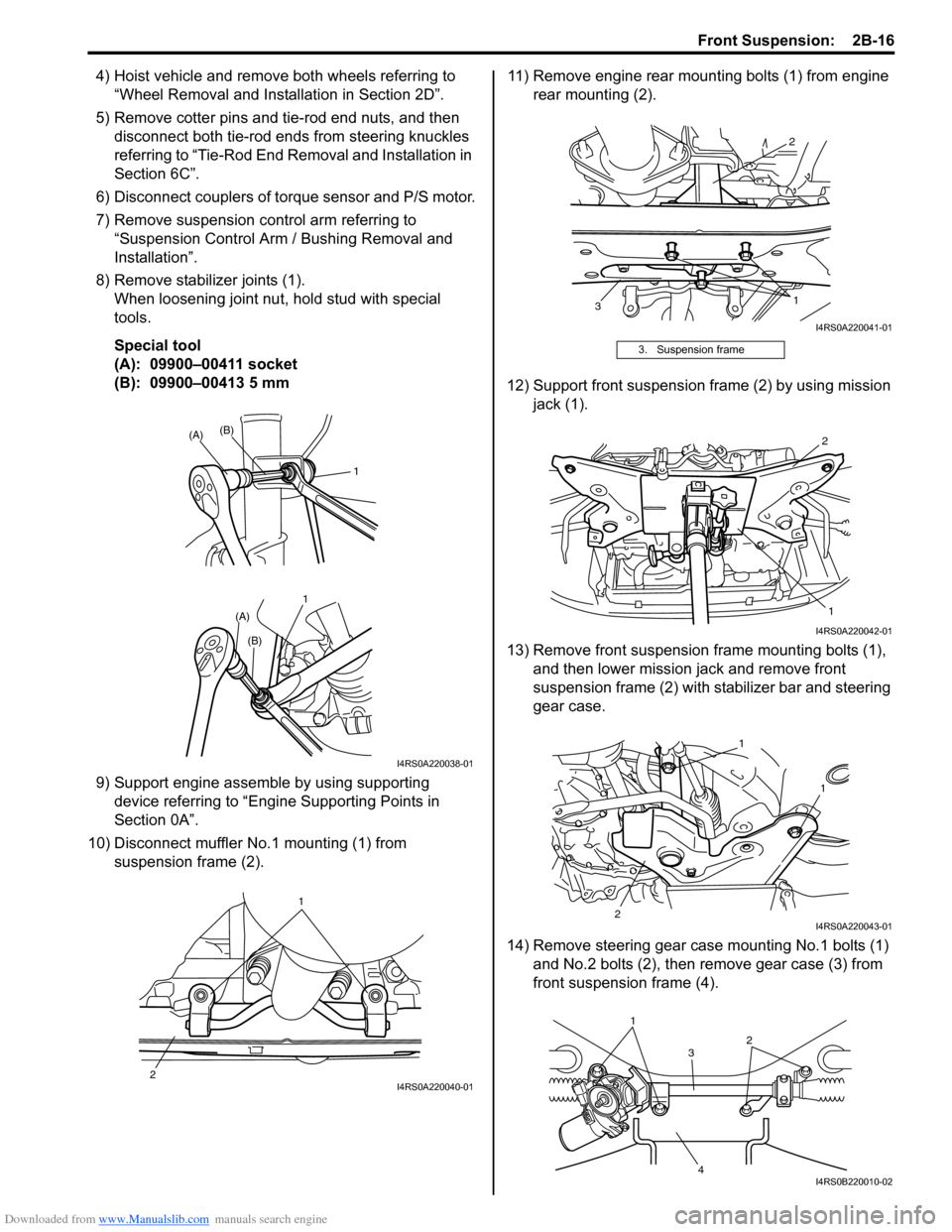
8) Remove stabilizer joints (1). When loosening joint nu t, hold stud with special
tools.
Special tool
(A): 09900–00411 socket
(B): 09900–00413 5 mm
9) Support engine assemble by using supporting device referring to “Engine Supporting Points in
Section 0A”.
10) Disconnect muffler No.1 mounting (1) from suspension frame (2). 11) Remove engine rear mounting bolts (1) from engine
rear mounting (2).
12) Support front suspension frame (2) by using mission jack (1).
13) Remove front suspension frame mounting bolts (1), and then lower mission jack and remove front
suspension frame (2) with st abilizer bar and steering
gear case.
14) Remove steering gear case mounting No.1 bolts (1) and No.2 bolts (2), then remove gear case (3) from
front suspensio n frame (4).
11
(A)
(A)
(B)
(B)
I4RS0A220038-01
1
2
I4RS0A220040-01
3. Suspension frame
2
3 1
I4RS0A220041-01
2
1
I4RS0A220042-01
1
2 1
I4RS0A220043-01
1
3
4 2
I4RS0B220010-02
Page 451 of 1496
Downloaded from www.Manualslib.com manuals search engine Front Suspension: 2B-18
7) Tighten front suspension frame mounting bolts (a) to specified torque.
Tightening torque
Front suspension frame mounting bolt (a): 150
N·m (15.0 kgf-m, 108.5 lb-ft)
8) Lower mission jack.
9) Tighten engine rear mounting bolts (a) to specified torque.
Tightening torque
Engine rear mounting bolt (a): 55 N·m (5.5 kgf-
m, 40.0 lb-ft)
10) Connect muffler No.1 mounting (1) to front suspension frame (2). 11) Remove supporting device from engine.
12) Install stabilizer joints (1), and tighten nuts to
specified torque.
When tightening, hold stud with special tools.
Special tool
(A): 09900–00411 socket
(B): 09900–00413 5 mm
Tightening torque
Stabilizer joint nut (a): 50 N·m (5.0 kgf-m, 36.5
lb-ft)
2. Engine rear mounting 3. Suspension frame
(a)
(a)
I4RS0A220048-01
2
3 (a)
I4RS0A220049-01
1
2
I4RS0A220040-01
1 1
(A)
(A)
(a) (a)
(B)
(B)
I4RS0A220051-01
Page 823 of 1496

Downloaded from www.Manualslib.com manuals search engine Manual Transmission/Transaxle: 5B-9
Manual Transaxle Unit Dismounting and
Remounting
S7RS0B5206009
Dismounting1) Drain coolant and transaxle oil.
2) Remove coolant reservoir with reservoir hose.
3) Remove battery and tray.
4) Remove air cleaner case and resonator.
5) Disconnect gear shift and gear select control cables (1) while pressing claws (2) of clip (3).
6) Disconnect back up light switch coupler and undo wiring harness clamps.
7) Remove ground cable from transaxle.
8) Remove clutch operating cylinder with fluid hose from transaxle.
9) Remove water inlet No.2 pipe from transaxle.
10) Remove starting motor re ferring to “Starting Motor
Dismounting and Remounting in Section 1I”.
11) Remove transaxle to engine bolts (1) of upper side. 12) Support engine using supporting device (1).
CAUTION!
Do not apply supporting device to projection
part A. If do so, it may be deformed.
13) Remove front drive shafts and center shaft referring
to “Front Drive Shaft Assembly Removal and
Installation in Section 3A”.
14) Remove exhaust No.2 pipe referring to “Exhaust Pipe and Muffler Removal a nd Installation in Section
1K”.
15) Remove clutch housing lower plate (1).
1
2
3
I7RS0A521003-01
1
1
I4RS0A520018-01
1
A
I4RS0A520019-01
1I4RS0A520020-01