2008 SUZUKI SWIFT ambient
[x] Cancel search: ambientPage 959 of 1496
Downloaded from www.Manualslib.com manuals search engine Air Conditioning System: Manual Type 7B-11
5) Warm up engine to the normal operating temperature and keep it at the specified idle speed.
6) Turn A/C switch ON, set blower speed selector at maximum speed position, temperature selector at
maximum cold position, airflow selector at face
position, and air intake switch at recirculation
position. (Confirm that A/C compressor and
condenser fans are working.)
7) Wait for ten minutes to stabilize the A/C operation.
8) Open front windows, front doors and engine hood.
9) With about 20 mm (0.8 in.) of dry bulb thermometer
(1) put right in front of center ventilation louver and a
wet and dry bulb thermometer (2) near air inlet of
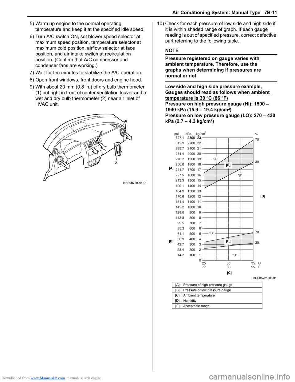
HVAC unit. 10) Check for each pressure of low side and high side if
it is within shaded range of graph. If each gauge
reading is out of specified pressure, correct defective
part referring to the following table.
NOTE
Pressure registered on gauge varies with
ambient temperature. Therefore, use the
graphs when determining if pressures are
normal or not.
Low side and high side pressure example,
Gauges should read as follows when ambient
temperature is 30 °C (86 °F)
Pressure on high pressure gauge (HI): 1590 –
1940 kPa (15.9 – 19.4 kg/cm2)
Pressure on low pressure gauge (LO): 270 – 430
kPa (2.7 – 4.3 kg/cm
2)
2
1
I4RS0B720004-01
[A]: Pressure of high pressure gauge
[B]: Pressure of low pressure gauge
[C]: Ambient temperature
[D]: Humidity [E]: Acceptable range
22
312.9 2200
0 1
2 3 30 70 30 70 %
4 5 6 7 8 9
10
11 12 13 14 15
16 17
18
19 21
298.7 2100
20
14.2 28.4 42.7 56.9 71.1 85.3 99.5
113.8 128.0 142.2
151.4
170.6
184.9 199.1
213.3 227.5
241.7
256.0
270.2
284.4
100 200 300 400 500 600 700 800 900
1000 1100 1200
1300
1400 1500 1600
1700 1800
1900
2000
25 30 35
77 86 95
psi kPa kg/cm
2
C
F
“A”
“B”
“C”
“D”
23
2300
327.1
[A]
[B]
[C][D][E]
[E]
I7RS0A721006-01
Page 961 of 1496
Downloaded from www.Manualslib.com manuals search engine Air Conditioning System: Manual Type 7B-13
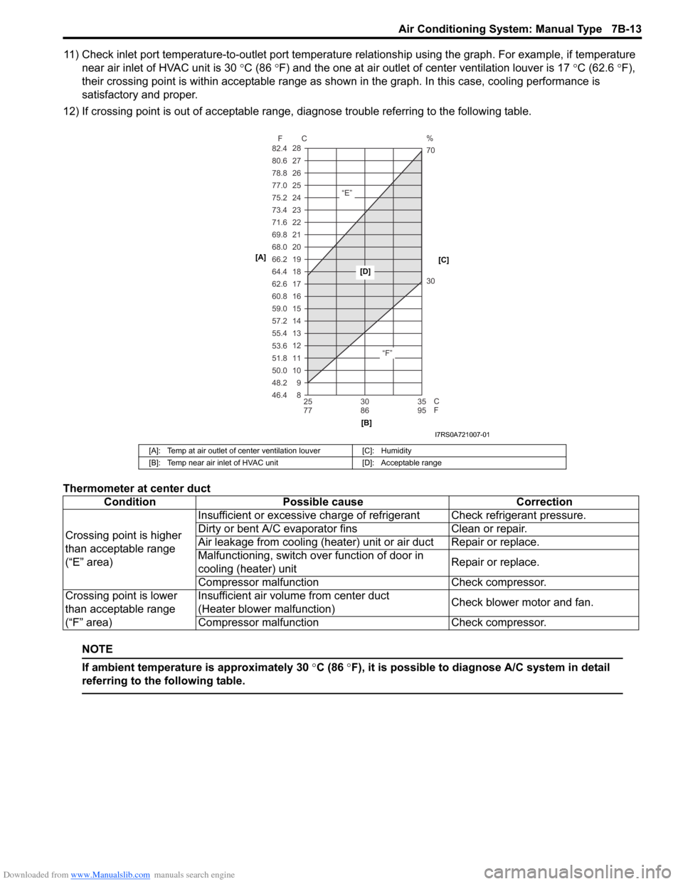
11) Check inlet port temperature-to-outlet port temperature relationship using the graph. For example, if temperature
near air inlet of HVAC unit is 30 °C (86 °F) and the one at air outlet of center ventilation louver is 17 °C (62.6 °F),
their crossing point is within acceptable range as shown in the graph. In this case, cooling performance is
satisfactory and proper.
12) If crossing point is out of acceptable range, diagnose trouble referring to the following table.
Thermometer at center duct
NOTE
If ambient temperature is approximately 30 °C (86 °F), it is possible to diagnose A/C system in detail
referring to the following table.
[A]: Temp at air outlet of center ventilation louver [C]: Humidity
[B]: Temp near air inlet of HVAC unit [D]: Acceptable range
ConditionPossible cause Correction
Crossing point is higher
than acceptable range
(“E” area) Insufficient or excessive charge of refrigerant Check refrigerant pressure.
Dirty or bent A/C evaporator fins
Clean or repair.
Air leakage from cooling (heater) unit or air duct Repair or replace.
Malfunctioning, switch over function of door in
cooling (heater) unit Repair or replace.
Compressor malfunct ion Check compressor.
Crossing point is lower
than acceptable range
(“F” area) Insufficient air volume from center duct
(Heater blower malfunction)
Check blower motor and fan.
Compressor malfunct ion Check compressor.
8 9
10 11 12 13 14
15 16 17 18 19
20
21
22
23
24
25 26
27
28
46.4 48.2 50.0 51.8 53.6 55.4 57.2 59.0 60.8 62.6 64.4
66.2 68.0
69.8
71.6
73.4
75.2
77.0
78.8 80.6
82.4
25 30 35
77 86 95
F C
C
F
“E”
“F”30 70 %
[A]
[B][C]
[D]
I7RS0A721007-01
Page 968 of 1496
Downloaded from www.Manualslib.com manuals search engine 7B-20 Air Conditioning System: Manual Type
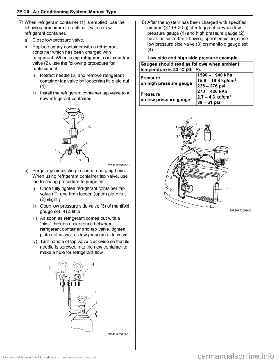
7) When refrigerant container (1) is emptied, use the following procedure to replace it with a new
refrigerant container.
a) Close low pressure valve.
b) Replace empty container with a refrigerant container which has been charged with
refrigerant. When using refrigerant container tap
valve (2), use the following procedure for
replacement.
i) Retract needle (3) and remove refrigerant container tap valve by loosening its plate nut
(4).
ii) Install the refrigerant container tap valve to a new refrigerant container.
c) Purge any air existing in center charging hose. When using refrigerant container tap valve, use
the following procedure to purge air.
i) Once fully tighten refrigerant container tap valve (1), and then loosen (open) plate nut
(2) slightly.
ii) Open low pressure side valve (3) of manifold
gauge set (4) a little.
iii) As soon as refrigerant comes out with a “hiss” through a clearance between
refrigerant container and tap valve, tighten
plate nut as well as low pressure side valve.
iv) Turn handle of tap valve clockwise so that its needle is screwed into the new container to
make a hole for refrigerant flow. 8) After the system has been charged with specified
amount (370 ± 20 g) of refrigerant or when low
pressure gauge (1) and high pressure gauge (2)
have indicated the following specified value, close
low pressure side valve (3) on manifold gauge set
(4).
Low side and high side pressure example
I2RH01720018-01
I2RH01720019-01
Gauges should read as follows when ambient
temperature is 30 °C (86 °F).
Pressure
on high pressure gauge 1590 – 1940 kPa
15.9 – 19.4 kg/cm
2
226 – 276 psi
Pressure
on low pressure gauge 270 – 430 kPa
2.7 – 4.3 kg/cm
2
38 – 61 psi
1
3 42
I4RS0A720016-01
Page 994 of 1496
Downloaded from www.Manualslib.com manuals search engine 7B-46 Air Conditioning System: Automatic Type
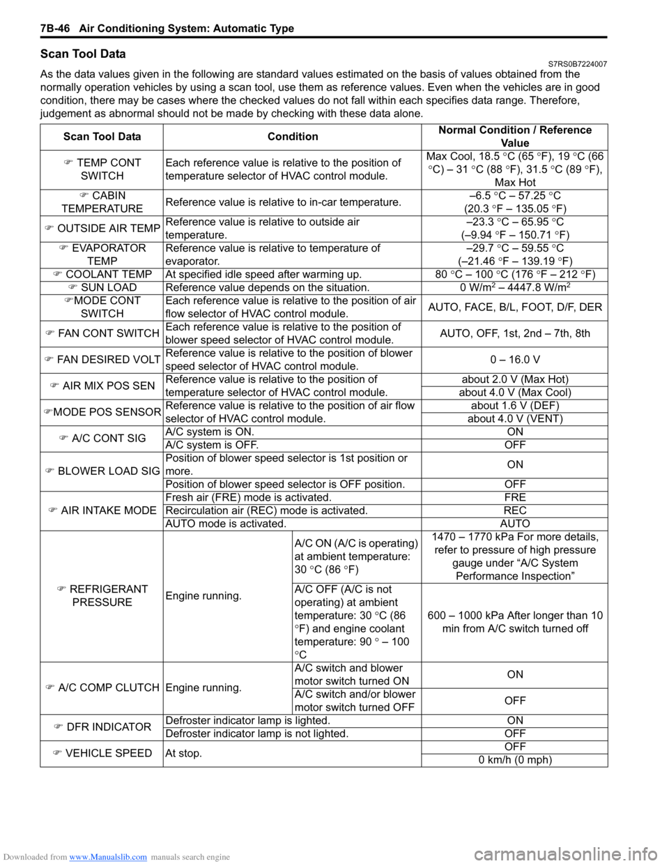
Scan Tool DataS7RS0B7224007
As the data values given in the following are standard values estimated on the basis of values obtained from the
normally operation vehicles by using a scan tool, use them as reference values. Even when the vehicles are in good
condition, there may be cases where the checked values do not fall within each specifies data range. Therefore,
judgement as abnormal should not be ma de by checking with these data alone.
Scan Tool Data Condition Normal Condition / Reference
Va l u e
�) TEMP CONT
SWITCH Each reference value is relative to the position of
temperature selector of HVAC control module. Max Cool, 18.5
°C (65 ° F), 19 °C (66
° C) – 31 °C (88 °F), 31.5 °C (89 °F),
Max Hot
�) CABIN
TEMPERATURE Reference value is relative to in-car temperature. –6.5
°C – 57.25 ° C
(20.3 °F – 135.05 °F)
�) OUTSIDE AIR TEMP Reference value is relative to outside air
temperature. –23.3
°C – 65.95 °C
(–9.94 °F – 150.71 °F)
�) EVAPORATOR
TEMP Reference value is relative to temperature of
evaporator. –29.7
°C – 59.55 °C
(–21.46 °F – 139.19 °F)
�) COOLANT TEMP At specified id le speed after warming up. 80 °C – 100 °C (176 ° F – 212 ° F)
�) SUN LOAD Reference value depends on the situation. 0 W/m
2 – 4447.8 W/m2
�)MODE CONT
SWITCH Each reference value is relative to the position of air
flow selector of HVAC control module.
AUTO, FACE, B/L, FOOT, D/F, DER
�) FAN CONT SWITCH Each reference value is relative to the position of
blower speed selector of HVAC control module. AUTO, OFF, 1st, 2nd – 7th, 8th
�) FAN DESIRED VOLT Reference value is relative to the position of blower
speed selector of HVAC control module. 0 – 16.0 V
�) AIR MIX POS SEN Reference value is relative to the position of
temperature selector of HVAC control module. about 2.0 V (Max Hot)
about 4.0 V (Max Cool)
�) MODE POS SENSOR Reference value is relative to the position of air flow
selector of HVAC control module. about 1.6 V (DEF)
about 4.0 V (VENT)
�) A/C CONT SIG A/C system is ON. ON
A/C system is OFF. OFF
�) BLOWER LOAD SIG Position of blower speed selector is 1st position or
more.
ON
Position of blower speed selector is OFF position. OFF
�) AIR INTAKE MODE Fresh air (FRE) mode is activated. FRE
Recirculation air (REC) mode is activated. REC
AUTO mode is activated. AUTO
�) REFRIGERANT
PRESSURE Engine running. A/C ON (A/C is operating)
at ambient temperature:
30
°C (86 °F) 1470 – 1770 kPa For more details,
refer to pressure of high pressure
gauge under “A/C System Performance Inspection”
A/C OFF (A/C is not
operating) at ambient
temperature: 30 °C (86
° F) and engine coolant
temperature: 90 ° – 100
° C 600 – 1000 kPa After longer than 10
min from A/C switch turned off
�) A/C COMP CLUTCH Engine running. A/C switch and blower
motor switch turned ON
ON
A/C switch and/or blower
motor switch turned OFF OFF
�) DFR INDICATOR Defroster indicator
lamp is lighted. ON
Defroster indicator la mp is not lighted. OFF
�) VEHICLE SPEED At stop. OFF
0 km/h (0 mph)
Page 1041 of 1496
Downloaded from www.Manualslib.com manuals search engine Air Bag System: 8B-3
• Never attempt disassembly of the air bag (inflator) modules.
• If any abnormality is found, be sure to replace it with
new one as an assembly.
• When an abnormality is noted as existing in the live (undeployed) air bag (inflator) module, be sure to
deploy it before discarding it.
• When grease, cleaning agent, oil, water, etc., got on the air bag (inflator) modules (driver, passenger, side
of both sides and curtain of both sides), wipe it off
immediately with a dry cloth.
• If air bag (inflator) module was dropped from a height of 90 cm (3 ft) or more, it should be replaced with a
new one as an assembly.
WARNING!
• For handling and storage of a live air bag (inflator) module, select a place where the
ambient temperature below 65 °C (150 ° F),
without high humidity and away from
electric noise.
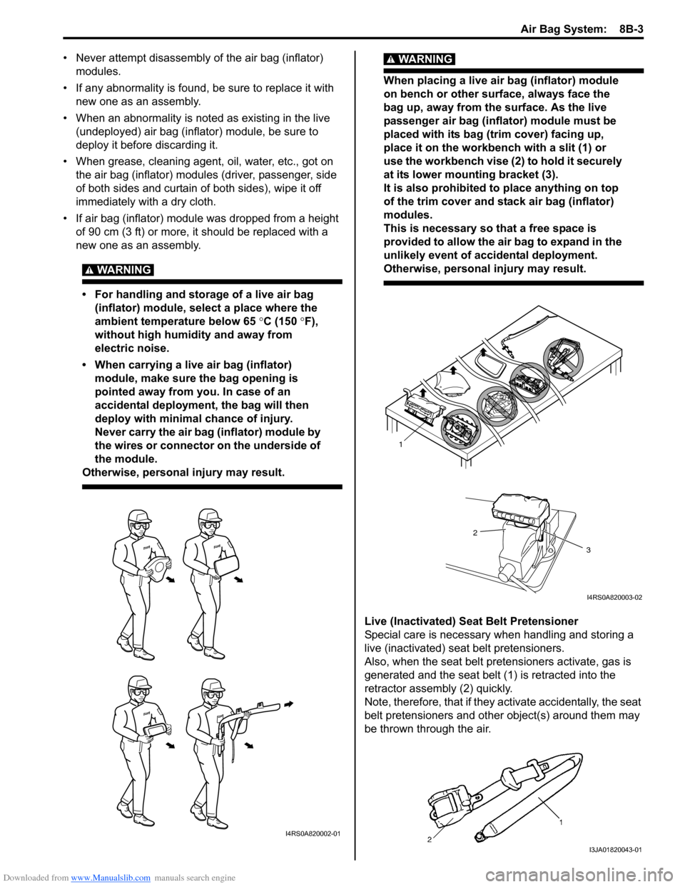
• When carrying a live air bag (inflator) module, make sure the bag opening is
pointed away from you. In case of an
accidental deployment, the bag will then
deploy with minimal chance of injury.
Never carry the air bag (inflator) module by
the wires or connector on the underside of
the module.
Otherwise, personal injury may result.
WARNING!
When placing a live air bag (inflator) module
on bench or other surface, always face the
bag up, away from the surface. As the live
passenger air bag (inflator) module must be
placed with its bag (trim cover) facing up,
place it on the workbench with a slit (1) or
use the workbench vise (2) to hold it securely
at its lower mounting bracket (3).
It is also prohibited to place anything on top
of the trim cover and stack air bag (inflator)
modules.
This is necessary so that a free space is
provided to allow the air bag to expand in the
unlikely event of accidental deployment.
Otherwise, personal injury may result.
Live (Inactivated) Seat Belt Pretensioner
Special care is necessary when handling and storing a
live (inactivated) seat belt pretensioners.
Also, when the seat belt pretensioners activate, gas is
generated and the seat belt (1) is retracted into the
retractor assembly (2) quickly.
Note, therefore, that if they activate accidentally, the seat
belt pretensioners and other object(s) around them may
be thrown through the air.
I4RS0A820002-01
1
2
3
I4RS0A820003-02
I3JA01820043-01
Page 1042 of 1496
Downloaded from www.Manualslib.com manuals search engine 8B-4 Air Bag System:
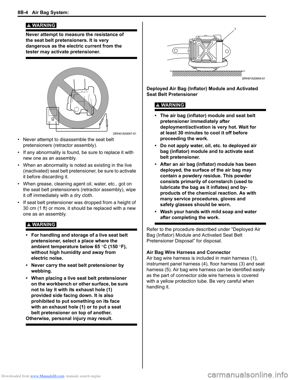
WARNING!
Never attempt to measure the resistance of
the seat belt pretensioners. It is very
dangerous as the electric current from the
tester may activate pretensioner.
• Never attempt to disassemble the seat belt
pretensioners (retractor assembly).
• If any abnormality is found, be sure to replace it with
new one as an assembly.
• When an abnormality is noted as existing in the live (inactivated) seat belt preten sioner, be sure to activate
it before discarding it.
• When grease, cleaning agent oil, water, etc., got on the seat belt pretensioners (r etractor assembly), wipe
it off immediately with a dry cloth.
• If seat belt pretensioner was dropped from a height of 30 cm (1 ft) or more, it should be replaced with a new
one as an assembly.
WARNING!
• For handling and storage of a live seat belt pretensioner, select a place where the
ambient temperature below 65 °C (150 ° F),
without high humidity and away from
electric noise.
• Never carry the seat belt pretensioner by webbing.
• When placing a live seat belt pretensioner on the workbench or other surface, be sure
not to lay it with its exhaust hole (1)
provided side facing down. It is also
prohibited to put something on its face
with an exhaust hole (1) or to put a seat
belt pretensioner on top of another.
Otherwise, personal injury may result.
Deployed Air Bag (Inflator) Module and Activated
Seat Belt Pretensioner
WARNING!
• The air bag (inflator) module and seat belt
pretensioner immediately after
deployment/activation is very hot. Wait for
at least 30 minutes to cool it off before
proceeding the work.
• Do not apply water, oil, etc. to deployed air bag (inflator) module and to activate seat
belt pretensioner.
• After an air bag (inflator) module has been deployed, the surface of the air bag may
contain a powdery residue. This powder
consists primarily of cornstarch (used to
lubricate the bag as it inflates) and by-
products of the chemical reaction. As with
many service procedures, gloves and
safety glasses should be worn.
• Wash your hands with mild soap and water after completing the work.
Refer to the procedure described under “Deployed Air
Bag (Inflator) Module and Activated Seat Belt
Pretensioner Disposal” for disposal.
Air Bag Wire Harness and Connector
Air bag wire harness is includ ed in main harness (1),
instrument panel harness (4), floor harness (3) and seat
harness (5). Air bag wire harness can be identified easily
as the part of connector side wire harness is covered
with a yellow protection tube. Be very careful when
handling it.
I2RH01820047-01
1
I2RH01820048-01
Page 1152 of 1496
Downloaded from www.Manualslib.com manuals search engine 8B-114 Air Bag System:
Deployment / Activation Outside of Vehicle
When you intend to return the vehicle to service, deploy
the air bag (inflator) module(s) or activate seat belt
pretensioner(s) outside of the vehicle.1) Turn ignition switch to LOCK position and remove key.
2) Wear safety glasses during this deployment / activation procedure.
3) Check that there is no open, short or damage in special tools (deployment harness (A) and adapter
cable (B)). If any faulty is found, do not use it and be
sure to use new special tool.
Special tool
(A): 09932-75031
(B): 09932–76510
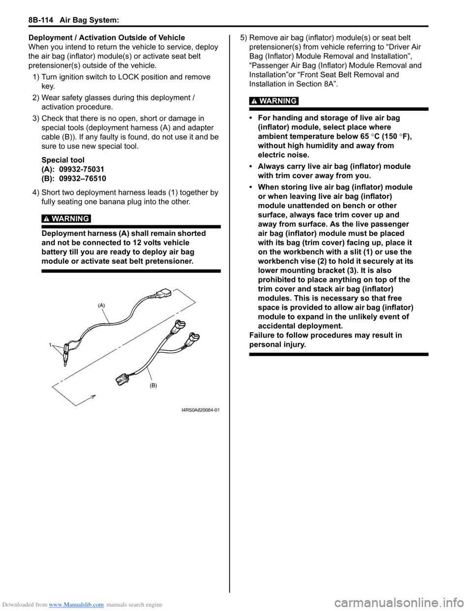
4) Short two deployment harness leads (1) together by fully seating one banana plug into the other.
WARNING!
Deployment harness (A) shall remain shorted
and not be connected to 12 volts vehicle
battery till you are ready to deploy air bag
module or activate seat belt pretensioner.
5) Remove air bag (inflator) module(s) or seat belt pretensioner(s) from vehicle referring to “Driver Air
Bag (Inflator) Module Re moval and Installation”,
“Passenger Air Bag (Inflator) Module Removal and
Installation”or “Front Seat Belt Removal and
Installation in Section 8A”.
WARNING!
• For handing and storage of live air bag (inflator) module, select place where
ambient temperature below 65 °C (150 °F),
without high humidity and away from
electric noise.
• Always carry live air bag (inflator) module with trim cover away from you.
• When storing live air bag (inflator) module or when leaving live air bag (inflator)
module unattended on bench or other
surface, always face trim cover up and
away from surface. As the live passenger
air bag (inflator) module must be placed
with its bag (trim cover) facing up, place it
on the workbench with a slit (1) or use the
workbench vise (2) to hold it securely at its
lower mounting bracket (3). It is also
prohibited to place anything on top of the
trim cover and stack air bag (inflator)
modules. This is necessary so that free
space is provided to allow air bag (inflator)
module to expand in the unlikely event of
accidental deployment.
Failure to follow procedures may result in
personal injury.
I4RS0A820084-01
Page 1153 of 1496
Downloaded from www.Manualslib.com manuals search engine Air Bag System: 8B-115
WARNING!
• For handling and storage of seat belt pretensioner, select place where ambient
temperature is below 65 °C (150 °F),
without high humidity and away from
electric noise.
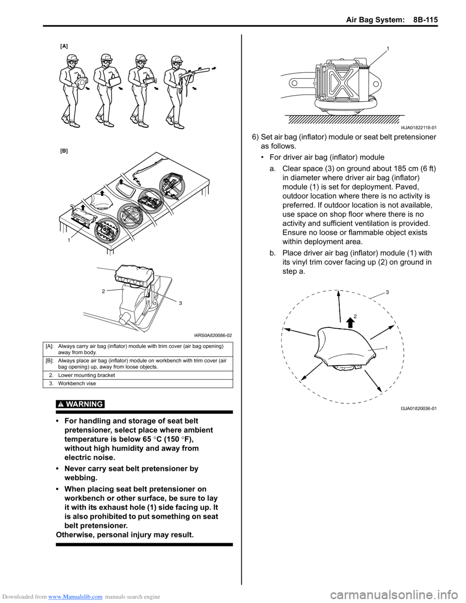
• Never carry seat belt pretensioner by webbing.
• When placing seat belt pretensioner on workbench or other surface, be sure to lay
it with its exhaust hole (1) side facing up. It
is also prohibited to put something on seat
belt pretensioner.
Otherwise, personal injury may result.
6) Set air bag (inflator) module or seat belt pretensioner
as follows.
• For driver air bag (inflator) module
a. Clear space (3) on ground about 185 cm (6 ft) in diameter where driver air bag (inflator)
module (1) is set for deployment. Paved,
outdoor location where there is no activity is
preferred. If outdoor location is not available,
use space on shop floor where there is no
activity and sufficient ventilation is provided.
Ensure no loose or flammable object exists
within deployment area.
b. Place driver air bag (inflator) module (1) with its vinyl trim cover facing up (2) on ground in
step a.
[A]: Always carry air bag (inflator) module with trim cover (air bag opening) away from body.
[B]: Always place air bag (inflator) module on workbench with trim cover (air bag opening) up, away from loose objects.
2. Lower mounting bracket
3. Workbench vise
1
2
3
[A]
[B]
I4RS0A820086-02
1
I4JA01822118-01
I3JA01820036-01