2008 SUZUKI SWIFT Window power
[x] Cancel search: Window powerPage 1207 of 1496
Downloaded from www.Manualslib.com manuals search engine Wiring Systems: 9A-36
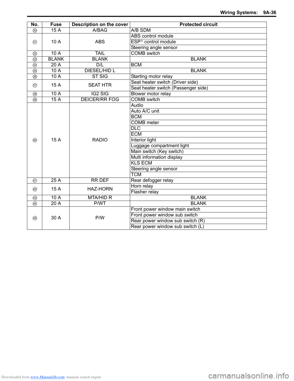
15 AA/BAG A/B SDM
10 A ABSABS control module
ESP
® control module
Steering angle sensor
10 A TAIL COMB switch
BLANK BLANK BLANK 20 A D/L BCM
10 A DIESEL/HID L BLANK
10 A ST SIG Starting motor relay
15 A SEAT HTR Seat heater switch (Driver side)
Seat heater switch (Passenger side)
10 A IG2 SIG Blower motor relay
15 A DEICER/RR FOG COMB switch
15 A RADIO Audio
Auto A/C unit
BCM
COMB meter
DLC
ECM
Interior light
Luggage compartment light
Main switch (Key switch)
Multi information display
KLS ECM
Steering angle sensor
TCM
25 A RR DEF Rear defogger relay
15 A HAZ-HORN Horn relay
Flasher relay
10 A MTA/HID R BLANK
20 A P/WT BLANK
30 A P/W Front power window main switch
Front power window sub switch
Rear power window sub switch (R)
Rear power window sub switch (L)
No. Fuse Description on the cover Protected circuit
Page 1216 of 1496

Downloaded from www.Manualslib.com manuals search engine 9A-45 Wiring Systems:
System Circuit Diagram
System Circuit DiagramS7RS0B910E001
Refer to “A-1 Cranking System Circuit Diagram”.
Refer to “A-2 Charging System Circuit Diagram”.
Refer to “A-3 Ignition System Circuit Diagram”.
Refer to “A-4 Cooling System Circuit Diagram”.
Refer to “A-5 Engine and A/C Control System Circuit Diagram”.
Refer to “A-6 A/T Control System Circuit Diagram”.
Refer to “A-7 Immobilizer System Circuit Diagram”.
Refer to “A-8 Body Control System Circuit Diagram”.
Refer to “B-1 Windshield Wiper and Washer Circuit Diagram”.
Refer to “B-2 Rear Wiper and Washer Circuit Diagram”.
Refer to “B-3 Rear Defogger Circuit Diagram”.
Refer to “B-4 Power Window Circuit Diagram”.
Refer to “B-5 Power Door Lock Circuit Diagram”.
Refer to “B-6 Power Mi rror Circuit Diagram”.
Refer to “B-7 Horn Circuit Diagram”.
Refer to “B-8 Seat Heater Circuit Diagram”.
Refer to “B-9 Keyless Star t System Circuit Diagram”.
Refer to “C-1 Combination Me ter Circuit Diagram (Meter)”.
Refer to “C-2 Combination Mete r Circuit Diagram (Indicator)”.
Refer to “C-3 Combination Meter Circuit Diagram (Warning Light)”.
Refer to “D-1 Headlight System Circuit Diagram”.
Refer to “D-2 Position, Tail and Licence Plate Light System Circuit Diagram”.
Refer to “D-3 Front Fog Light System Circuit Diagram”.
Refer to “D-4 Illumination Light System Circuit Diagram”.
Refer to “D-5 Interior Li ght System Circuit Diagram”.
Refer to “D-6 Turn Signal and Hazard Warning Light System Circuit Diagram”.
Refer to “D-7 Brake Light System Circuit Diagram”.
Refer to “D-8 Back-Up Light System Circuit Diagram”.
Refer to “D-9 Headlight Beam Leveling System Circuit Diagram”.
Refer to “D-10 Rear Fog Light Circuit Diagram”.
Refer to “E-1 Heater System Circuit Diagram”.
Refer to “E-2 Auto A/C System Circuit Diagram”.
Refer to “F-1 Air-Bag System Circuit Diagram”.
Refer to “F-2 Anti-Lock Brake System Circuit Diagram”.
Refer to “F-3 Electronic Stabilit y Program System Circuit Diagram”.
Refer to “F-4 Power Steeri ng System Circuit Diagram”.
Refer to “G-1 Audio Sy stem Circuit Diagram”.
Refer to “G-2 Multi Information Display / Accessory Socket System Circuit Diagram”.
Page 1236 of 1496
Downloaded from www.Manualslib.com manuals search engine 9A-65 Wiring Systems:
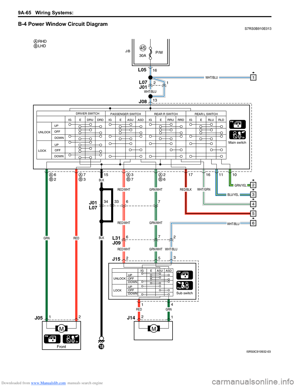
B-4 Power Window Circuit DiagramS7RS0B910E013
12
J15
L31J09
J01
L076
6
34
7
2
7
16
235
1011
1716
1
4
30A
P/W
45
Sub switch Main switch
J1421
GRNRED
RED
15
L05
J/B
18
BLK
BLK
2
13
WHT/BLU
WHT/BLU1
2
3
4
5
6
RED/WHTWHT/BLUGRN/WHT
RED/WHTGRN/WHT
RED/WHTGRN/WHTGRN/YEL
BLU/YEL
RED/BLK
M
GRN
J05
UNLOCK
LOCK
IG
DRIVER SWITCH
PASSENGER SWITCH REAR R SWITCH REAR L SWITCH
E DRU DRD
IG E ASU ASDIG E RLU RLDIG E RRU RRD
WHT/GRN
L07 J01
M
UP
OFF
DOWN
UP OFF
DOWN
J08
UNLOCK UP
OFF
DOWN
UP
OFF
DOWN
LOCK IG E ASU ASD
WHT/BLU
33
1
Front
RHD
LHD
AB
AB6
2AB7
3AB3
7AB2
6
I5RS0C910932-03
Page 1329 of 1496
Downloaded from www.Manualslib.com manuals search engine Glass / Windows / Mirrors: 9E-2
• Eyeleteer
• Piano string
• Windshield knife
• Brush for primer application (2 pcs)
•Knife
• Rubber sucker grip
• Sealant gun (for filling adhesive)
• Putty spatula (for correcting adhered parts)
Diagnostic Information and Procedures
Rear End door Window Defogger Symptom DiagnosisS7RS0B9504001
NOTE
• Use of SUZUKI scan tool makes it easy to check whether a faulty condition is on the input side or
output side of BCM. For checking procedure, re fer to “Diagnosis Using Output Test Function of
SUZUKI Scan Tool” under “Scan Tool Data in Section 10B”.
• Check each part in the order from the top of the following list.
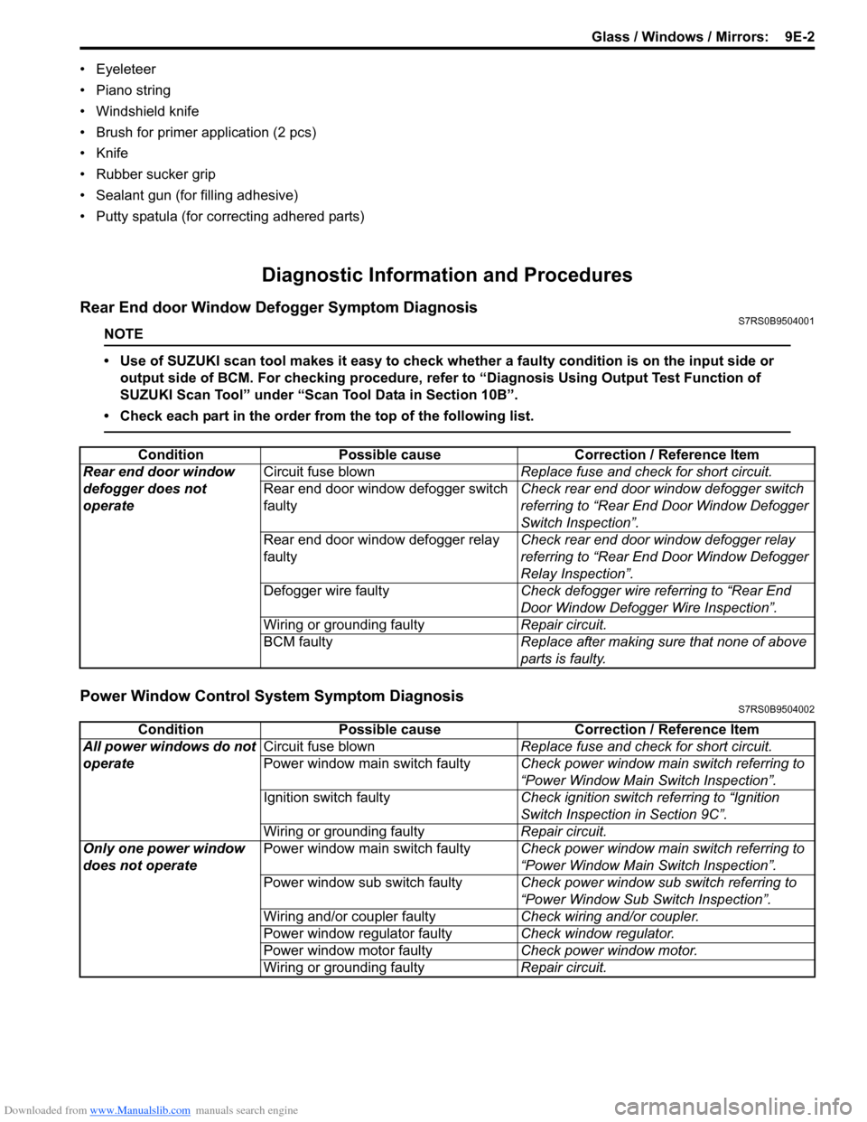
Power Window Control System Symptom DiagnosisS7RS0B9504002
Condition Possible cause Correction / Reference Item
Rear end door window
defogger does not
operate Circuit fuse blown
Replace fuse and check for short circuit.
Rear end door window defogger switch
faulty Check rear end door window defogger switch
referring to “Rear End Door Window Defogger
Switch Inspection”.
Rear end door window defogger relay
faulty Check rear end door window defogger relay
referring to “Rear End Door Window Defogger
Relay Inspection”.
Defogger wire faulty Check defogger wire referring to “Rear End
Door Window Defogger Wire Inspection”.
Wiring or grounding faulty Repair circuit.
BCM faulty Replace after making sure that none of above
parts is faulty.
ConditionPossible cause Correction / Reference Item
All power windows do not
operate Circuit fuse blown
Replace fuse and check for short circuit.
Power window main switch faulty Check power window main switch referring to
“Power Window Main Switch Inspection”.
Ignition switch faulty Check ignition switch referring to “Ignition
Switch Inspection in Section 9C”.
Wiring or grounding faulty Repair circuit.
Only one power window
does not operate Power window main switch faulty
Check power window main switch referring to
“Power Window Main Switch Inspection”.
Power window sub switch faulty Check power window sub switch referring to
“Power Window Sub Switch Inspection”.
Wiring and/or coupler faulty Check wiring and/or coupler.
Power window regulator faulty Check window regulator.
Power window motor faulty Check power window motor.
Wiring or grounding faulty Repair circuit.
Page 1330 of 1496
Downloaded from www.Manualslib.com manuals search engine 9E-3 Glass / Windows / Mirrors:
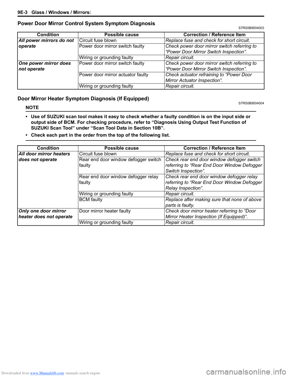
Power Door Mirror Control System Symptom DiagnosisS7RS0B9504003
Door Mirror Heater Symptom Diagnosis (If Equipped)S7RS0B9504004
NOTE
• Use of SUZUKI scan tool makes it easy to check whether a faulty condition is on the input side or
output side of BCM. For checking procedure, re fer to “Diagnosis Using Output Test Function of
SUZUKI Scan Tool” under “Scan Tool Data in Section 10B”.
• Check each part in the order from the top of the following list.
Condition Possible cause Correction / Reference Item
All power mirrors do not
operate Circuit fuse blown
Replace fuse and check for short circuit.
Power door mirror switch faulty Check power door mirror switch referring to
“Power Door Mirror Switch Inspection”.
Wiring or grounding faulty Repair circuit.
One power mirror does
not operate Power door mirror switch faulty
Check power door mirror switch referring to
“Power Door Mirror Switch Inspection”.
Power door mirror actuator faulty Check actuator refraining to “Power Door
Mirror Actuator Inspection”.
Wiring or grounding faulty Repair circuit.
ConditionPossible cause Correction / Reference Item
All door mirror heaters
does not operate Circuit fuse blown
Replace fuse and check for short circuit.
Rear end door window defogger switch
faulty Check rear end door window defogger switch
referring to “Rear End Door Window Defogger
Switch Inspection”.
Rear end door window defogger relay
faulty Check rear end door window defogger relay
referring to “Rear End Door Window Defogger
Relay Inspection”.
Wiring or grounding faulty Repair circuit.
BCM faulty Replace after making sure that none of above
parts is faulty.
Only one door mirror
heater does not operate Door mirror heater faulty
Check door mirror heater referring to “Door
Mirror Heater Inspection (If Equipped)”.
Wiring or grounding faulty Repair circuit.
Page 1335 of 1496
Downloaded from www.Manualslib.com manuals search engine Glass / Windows / Mirrors: 9E-8
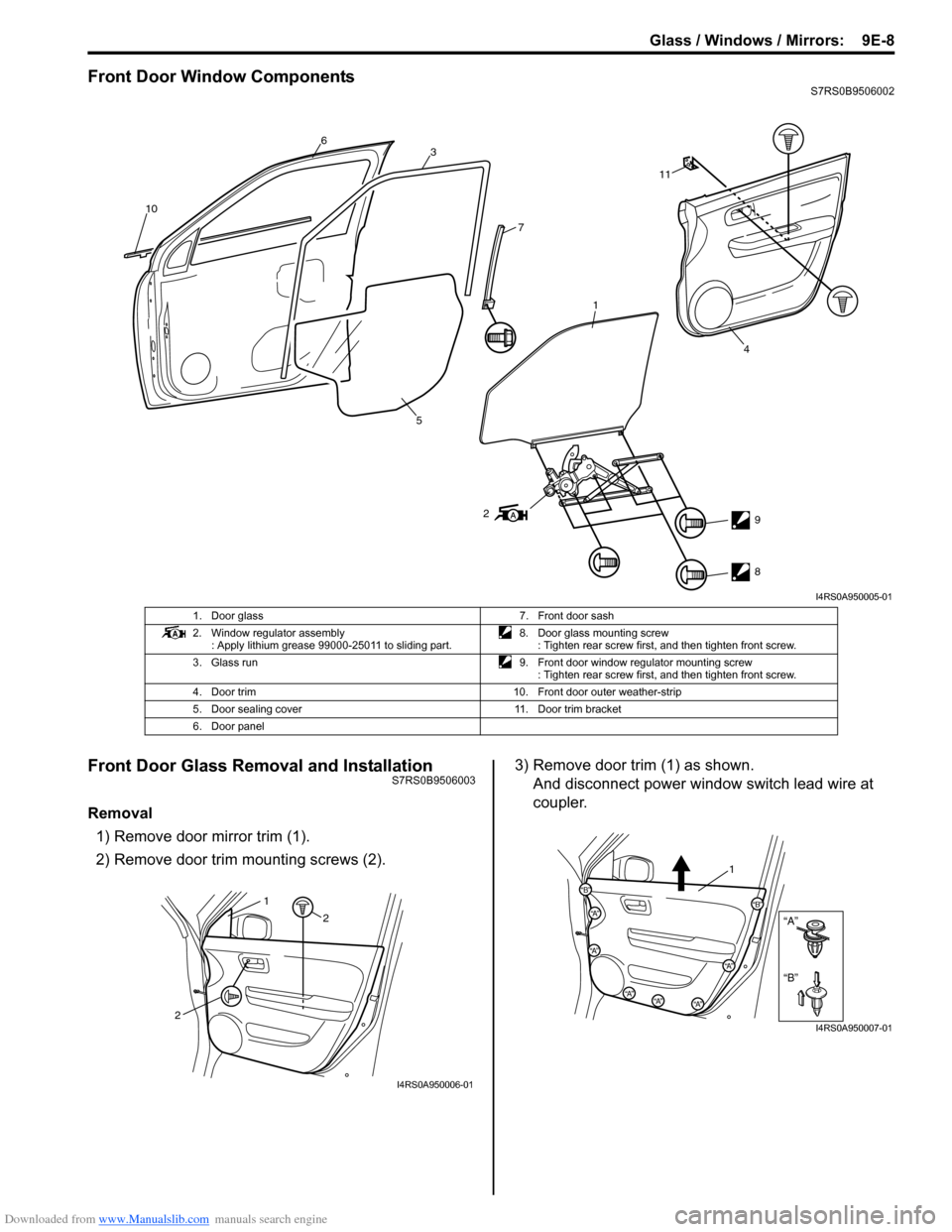
Front Door Window ComponentsS7RS0B9506002
Front Door Glass Removal and InstallationS7RS0B9506003
Removal1) Remove door mirror trim (1).
2) Remove door trim mounting screws (2). 3) Remove door trim (1) as shown.
And disconnect power window switch lead wire at
coupler.
10 6
3
1
7
11
5
2 9
8
4
I4RS0A950005-01
1. Door glass 7. Front door sash
2. Window regulator assembly : Apply lithium grease 99000-25011 to sliding part. 8. Door glass mounting screw
: Tighten rear screw first, and then tighten front screw.
3. Glass run 9. Front door window regulator mounting screw
: Tighten rear screw first, and then tighten front screw.
4. Door trim 10. Front door outer weather-strip
5. Door sealing cover 11. Door trim bracket
6. Door panel
2 2
1
I4RS0A950006-01
“B”
“A”
“B”
“A”
“B”“A”
“A”
“A”“A”“A”
1
I4RS0A950007-01
Page 1336 of 1496
Downloaded from www.Manualslib.com manuals search engine 9E-9 Glass / Windows / Mirrors:
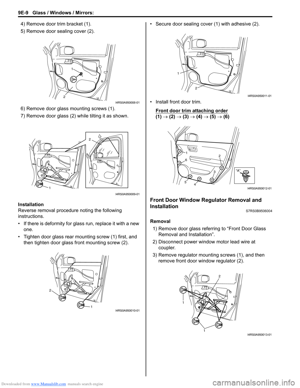
4) Remove door trim bracket (1).
5) Remove door sealing cover (2).
6) Remove door glass mounting screws (1).
7) Remove door glass (2) while tilting it as shown.
Installation
Reverse removal procedure noting the following
instructions.
• If there is deformity for glass run, replace it with a new one.
• Tighten door glass rear mounting screw (1) first, and then tighten door glass front mounting screw (2). • Secure door sealing cover (1) with adhesive (2).
• Install front door trim.
Front door trim attaching order
(1) → (2) → (3) → (4) → (5) → (6)
Front Door Window Regulator Removal and
Installation
S7RS0B9506004
Removal
1) Remove door glass referring to “Front Door Glass Removal and Installation”.
2) Disconnect power window motor lead wire at coupler.
3) Remove regulator mounting screws (1), and then remove front door window regulator (2).
1
2
I4RS0A950008-01
2
1
I4RS0A950009-01
1
2
I4RS0A950010-01
2
1
I4RS0A950011-01
“A”“A”
“A”
“A”
“A”“A”“A”
1 2
3
4
5 6
I4RS0A950012-01
1
1
2
I4RS0A950013-01
Page 1338 of 1496
Downloaded from www.Manualslib.com manuals search engine 9E-11 Glass / Windows / Mirrors:
Rear Door Glass Removal and InstallationS7RS0B9506007
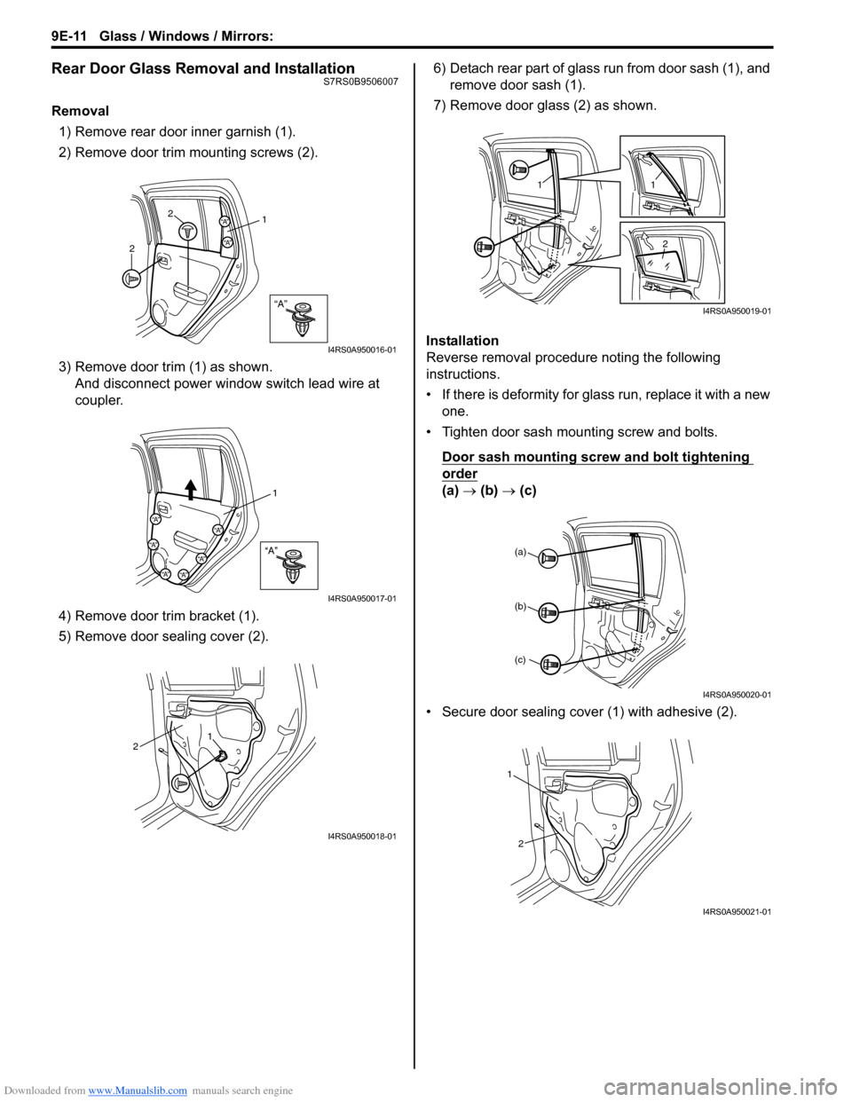
Removal1) Remove rear door inner garnish (1).
2) Remove door trim mounting screws (2).
3) Remove door trim (1) as shown. And disconnect power wi ndow switch lead wire at
coupler.
4) Remove door trim bracket (1).
5) Remove door sealing cover (2). 6) Detach rear part of glass run from door sash (1), and
remove door sash (1).
7) Remove door glass (2) as shown.
Installation
Reverse removal procedure noting the following
instructions.
• If there is deformity for glass run, replace it with a new one.
• Tighten door sash mounting screw and bolts.
Door sash mounting screw and bolt tightening
order
(a) → (b) → (c)
• Secure door sealing cover (1) with adhesive (2).
“A”
“A”
“A”
2
2 1
I4RS0A950016-01
“A”
“A”
“A”
“A”“A”
“A”
“A”
1
I4RS0A950017-01
1
2
I4RS0A950018-01
1
1
2
I4RS0A950019-01
(a)
(b)
(c)
I4RS0A950020-01
1
2
I4RS0A950021-01