2008 SUZUKI SWIFT Stop lamp switch
[x] Cancel search: Stop lamp switchPage 378 of 1496
Downloaded from www.Manualslib.com manuals search engine 1G-3 Fuel System:
4) Check that battery voltage is 11 V or more.
5) Measure fuel pressure at each condition.If measured pressure is out of specification, refer to
“Fuel Pressure Check in Section 1A” and check each
possibly defective part. Replace if found defective.
a) Turn ignition switch ON to operate fuel pump and after 2 seconds turn it OFF. Repeat this 3 or 4
times and then check fuel pressure.
Fuel pressure specification
With fuel pump operating and engine
stopped: 270 – 310 kPa (2.7 – 3.1 kg/cm2, 38.4
– 44.0 psi)
b) Start engine and warm it up to normal operating temperature, and measure fuel pressure at
idling.
Fuel pressure specification
At specified idle speed: 270 – 310 kPa (2.7 –
3.1 kg/cm2, 38.4 – 44.0 psi)
c) Stop engine, and measure fuel pressure at one minute after stopping.
Fuel pressure specification
With 1 min. after engine (fuel pump) stop
(Pressure reduces as time passes): Over 300
kPa (3.0 kg/cm
2, 42.7 psi)
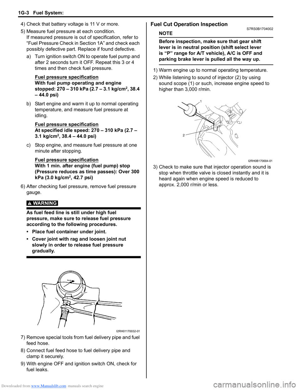
6) After checking fuel pressure, remove fuel pressure gauge.
WARNING!
As fuel feed line is still under high fuel
pressure, make sure to release fuel pressure
according to the following procedures.
• Place fuel container under joint.
• Cover joint with rag and loosen joint nut slowly in order to release fuel pressure
gradually.
7) Remove special tools from fuel delivery pipe and fuel feed hose.
8) Connect fuel feed hose to fuel delivery pipe and clamp it securely.
9) With engine OFF and ignition switch ON, check for fuel leaks.
Fuel Cut Operation InspectionS7RS0B1704002
NOTE
Before inspection, make sure that gear shift
lever is in neutral positi on (shift select lever
is “P” range for A/T vehicle), A/C is OFF and
parking brake lever is pulled all the way up.
1) Warm engine up to normal operating temperature.
2) While listening to sound of injector (2) by using sound scope (1) or such, increase engine speed to
higher than 3,000 r/min.
3) Check to make sure that injector operation sound is stop when throttle valve is closed instantly and it is
heard again when engine speed is reduced to
approx. 2,000 r/min or less.
I2RH01170032-01
I2RH0B170004-01
Page 382 of 1496

Downloaded from www.Manualslib.com manuals search engine 1G-7 Fuel System:
Fuel Pressure Relief ProcedureS7RS0B1706003
CAUTION!
This work must not be done when engine is
hot. If done so, it may cause adverse effect to
catalyst.
NOTE
If ECM detects DTC(s) after servicing, clear
DTC(s) referring to “DTC Clearance in
Section 1A”.
1) Make sure that engine is cold.
2) Shift transaxle gear shift lever in “Neutral” (shift select lever in “P” range for A/T model), set parking
brake and block drive wheels.
3) Remove relay / fuse box cover.
4) Disconnect fuel pump relay (1) from relay / fuse box (2).
5) Remove fuel filter cap in order to release fuel vapor pressure in fuel tank, and then reinstall it.
6) Start engine and run it until engine stops for lack of fuel. Repeat cranking engine 2 – 3 times for about 3
seconds each time in order to dissipate fuel pressure
in lines. Fuel connections are now safe for servicing.
7) After servicing, connect fuel pump relay (1) to relay / fuse box and install re lay / fuse box cover.
Fuel Leakage Check ProcedureS7RS0B1706004
After performing any service on fuel system, check to
make sure that there are no fuel leakages as follows.
1) Turn ON ignition switch for 3 seconds (to operate fuel pump) and then turn it OFF.
Repeat this (ON and OFF) 3 or 4 times and apply
fuel pressure to fuel line until fuel pressure is felt by
hand placed on fuel feed hose.
2) In this state, check to see that there are no fuel leakages from any part of fuel system.
Fuel Lines On-Vehicle InspectionS7RS0B1706005
CAUTION!
Due to the fact that fuel feed line (1) is under
high pressure, use special care when
servicing it.
Visually inspect fuel lines for evidence of fuel leakage,
hose crack and deterioration or damage.
Make sure all cl amps are secure.
Replace parts as needed.
Fuel Pipe Removal and InstallationS7RS0B1706006
WARNING!
Before starting the following procedure, be
sure to observe “Precautions on Fuel System
Service” in order to reduce the risk or fire
and personal injury.
Removal
1) Relieve fuel pressure in fuel feed line according to “Fuel Pressure Relief Procedure”.
2) Disconnect negative cable at battery.
3) Disconnect fuel pipe joint and fuel hose (3) from fuel pipe (2) at the front and rear of each fuel pipe
referring to “Fuel Hose Disconnecting and
Reconnecting”.
4) Mark the location of clamps (1) on fuel pipes (2), so that the clamps can be reinstalled to where they
were.
5) Remove pipes (2) with clamp (1) from vehicle.
6) Remove clamp (1) from pipes (2).
1
I4RS0A170004-01
1
I4RS0A170005-01
2
13
I4RS0A170020-01
Page 497 of 1496
Downloaded from www.Manualslib.com manuals search engine Table of Contents 4-iii
ABS Warning Lamp Check ............................... 4F-14
EBD Warning Lamp (Brake Warning Lamp) Check .............................................................. 4F-15
DTC Check ....................................................... 4F-15
DTC Table ......................................................... 4F-15
DTC Clearance ................................................. 4F-18
Fail-Safe Table ................ .................................. 4F-19
Scan Tool Data ................................................. 4F-20
Visual Inspection ............................................... 4F-21
ESP ® Warning Lamp Does Not Come ON at
Ignition Switch ON .......................................... 4F-21
ESP ® Warning Lamp Comes ON Steady......... 4F-22
ABS Warning Lamp Does Not Come ON at Ignition Switch ON .......................................... 4F-23
ABS Warning Lamp Comes ON Steady............ 4F-24
EBD Warning Lamp (Brake Warning Lamp) Comes ON Steady .......................................... 4F-24
Serial Data Link Circuit Check .......................... 4F-26
DTC C1016: Stop Lamp Swit ch Circuit Failure .. 4F-28
DTC C1017 / C1023: Yaw Rate / G Sensor Assembly Failure ............................................ 4F-29
DTC C1018: Brake Fluid Le vel Switch Failure .. 4F-30
DTC 1020: Master Cylinder Pressure Sensor Power Supply Failure ...................................... 4F-31
DTC C1021, C1022 / C1025, C1026 / C1031, C1032 / C1035, C1036: Wheel Speed
Sensor Circuit or Encode r Failure ................... 4F-32
DTC C1024: Steering Angle Sensor Circuit
Failure ............................................................. 4F-34
DTC C1027: ESP ® OFF Switch Circuit
Failure ............................................................. 4F-34
DTC C1028: Master Cylinder Pressure Sensor Circuit Failure ....... .............................. 4F-35
DTC C1034: Yaw Rate / G Sensor Assembly Power Supply Failure ...................................... 4F-36
DTC C1037: Steering Angle Sensor Power Supply Failure ................................................. 4F-37
DTC C1038: Steering Angle Sensor Detect Rolling Counter Fa ilure from ESP® Control
Module ............................................................ 4F-38
DTC C1039: Yaw Rate / G Sensor Assembly Internal Failure .............. .................................. 4F-39
DTC C1040: Stability Control System Function Failure .............................................. 4F-39
DTC C1041 / C1042 / C1043 / C1044 / C1045 / C1046 / C1051 / C1052 / C1053 / C1054 /
C1055 / C1056: Solenoid Circuit Failure ......... 4F-40
DTC C1057: ESP ® Control Module Power
Supply Circuit Failure .... .................................. 4F-41
DTC C1061: Pump Motor and/or Motor Driver Circuit Failure .................................................. 4F-42
DTC C1063: Solenoid Valve Power Supply Driver Circuit Failure ....................................... 4F-43
DTC 1071: ESP ® Control Module Internal
Defect.............................................................. 4F-44 DTC C1073: Lost Communication With Yaw
Rate / G Sensor Assembly .............................. 4F-45
DTC C1075 / 1076 / 1078: Sensor Calibration Incomplete.......................... ............................. 4F-46
DTC C1090: Invalid Communication with
ECM ................................................................ 4F-47
DTC C1091 / C1094: ECM Data in CAN Line Failure / Invalid Torque Control
Communication with ECM .. ............................. 4F-48
DTC U1073: Control Module Communication Bus Off ............................................................ 4F-49
DTC U1100: Lost Communication with ECM (Reception Error)............................................. 4F-50
DTC U1126: Lost Communication with Steering Angle Sensor (Reception Error)........ 4F-51
DTC U1140: Lost Communication with BCM (Reception Error)............................................. 4F-52
Repair Instructions ........... ................................. 4F-54
ESP® Hydraulic Unit Operation Check ............. 4F-54
Sensor Calibration............................................. 4F-54
ESP® Hydraulic Unit / Control Module
Assembly On-Vehicle Inspection .................... 4F-55
ESP ® Hydraulic
Unit / Control Module
Assembly Removal and Inst allation ................ 4F-56
Front / Rear Wheel Speed Sensor On-Vehicle Inspection ........................................................ 4F-57
Front Wheel Speed Sensor Removal and Installation ....................................................... 4F-58
Front Wheel Speed Sensor Inspection ............. 4F-59
Rear Wheel Speed Sensor Removal and Installation ....................................................... 4F-59
Rear Wheel Speed Sensor Inspection .............. 4F-60
Front Wheel Encode r On-Vehicle Inspection .... 4F-61
Front Wheel Encoder Removal and Installation ....................................................... 4F-61
Rear Wheel Encoder On-Veh icle Inspection..... 4F-61
Rear Wheel Encoder Removal and Installation ....................................................... 4F-61
Master Cylinder Pressure Sensor On-Vehicle
Inspection ........................................................ 4F-61
Yaw Rate / G Sensor Assembly On-Vehicle Inspection ........................................................ 4F-62
Yaw Rate / G Sensor Assembly Removal and Installation ....................................................... 4F-63
Yaw Rate / G Sensor Inspection ....................... 4F-64
Steering Angle Sensor On-Vehicle Inspection .. 4F-64
Steering Angle Sensor Removal and Installation ....................................................... 4F-65
Steering Angle Sensor Inspection ..................... 4F-65
ESP® OFF Switch Removal an d Installation .... 4F-65
ESP® OFF Switch Inspection ........................... 4F-65
Specifications .................... ................................. 4F-66
Tightening Torque Specifications ...................... 4F-66
Special Tools and Equipmen t ........................... 4F-66
Special Tool ...................................................... 4F-66
Page 506 of 1496
Downloaded from www.Manualslib.com manuals search engine 4A-8 Brake Control System and Diagnosis:
Excessive Pedal Travel InspectionS7RS0B4106003
1) Start engine.
2) Depress brake pedal a few times.
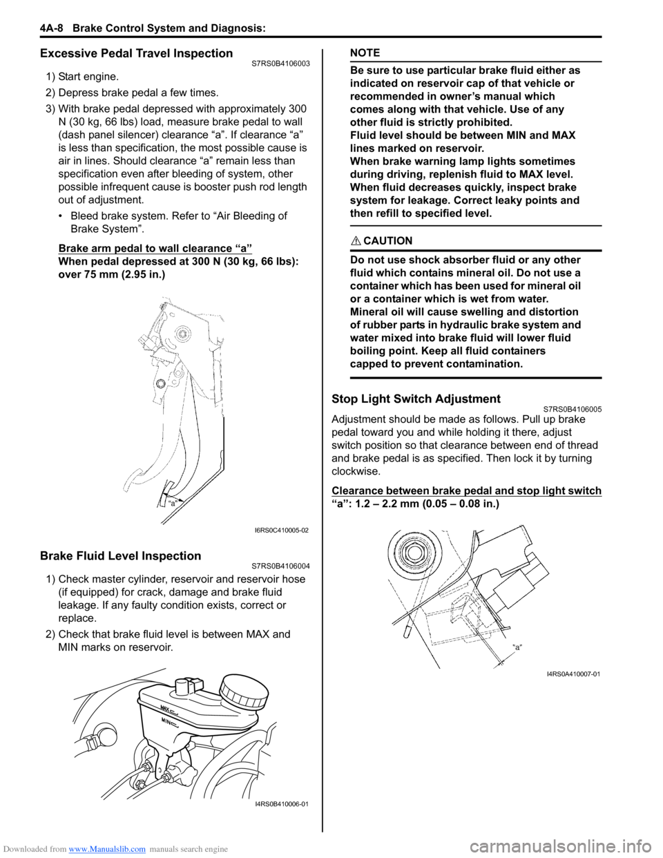
3) With brake pedal depressed with approximately 300 N (30 kg, 66 lbs) load, measure brake pedal to wall
(dash panel silencer) clearance “a”. If clearance “a”
is less than specification, the most possible cause is
air in lines. Should clearance “a” remain less than
specification even after bleeding of system, other
possible infrequent cause is booster push rod length
out of adjustment.
• Bleed brake system. Refer to “Air Bleeding of Brake System”.
Brake arm pedal to wall clearance “a”
When pedal depressed at 300 N (30 kg, 66 lbs):
over 75 mm (2.95 in.)
Brake Fluid Level InspectionS7RS0B4106004
1) Check master cylinder, reservoir and reservoir hose (if equipped) for crack, damage and brake fluid
leakage. If any faulty condition exists, correct or
replace.
2) Check that brake fluid level is between MAX and MIN marks on reservoir.
NOTE
Be sure to use particular brake fluid either as
indicated on reservoir cap of that vehicle or
recommended in owner’s manual which
comes along with that vehicle. Use of any
other fluid is strictly prohibited.
Fluid level should be between MIN and MAX
lines marked on reservoir.
When brake warning lamp lights sometimes
during driving, replenis h fluid to MAX level.
When fluid decreases quickly, inspect brake
system for leakage. Correct leaky points and
then refill to specified level.
CAUTION!
Do not use shock absorber fluid or any other
fluid which contains mineral oil. Do not use a
container which has been used for mineral oil
or a container which is wet from water.
Mineral oil will cause swelling and distortion
of rubber parts in hydraulic brake system and
water mixed into brake fluid will lower fluid
boiling point. Keep all fluid containers
capped to prevent contamination.
Stop Light Switch AdjustmentS7RS0B4106005
Adjustment should be made as follows. Pull up brake
pedal toward you and while holding it there, adjust
switch position so that clea rance between end of thread
and brake pedal is as specified. Then lock it by turning
clockwise.
Clearance between brake pedal and stop light switch
“a”: 1.2 – 2.2 mm (0.05 – 0.08 in.)
I6RS0C410005-02
I4RS0B410006-01
I4RS0A410007-01
Page 543 of 1496
Downloaded from www.Manualslib.com manuals search engine ABS: 4E-4
Schematic and Routing Diagram
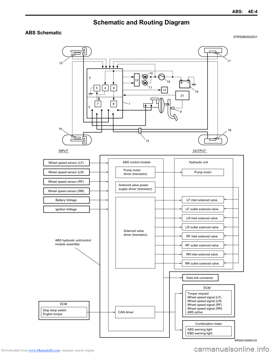
ABS SchematicS7RS0B4502001
INPUTOUTPUT
ABS control moduleWheel speed sensor (LF)
Wheel speed sensor (LR)
Wheel speed sensor (RF)Battery Voltage
Ignition Voltage
Pump motor
driver (transistor)
Solenoid valve power
supply driver (transistor)
Solenoid valve
driver (transistor) Hydraulic unit
Pump motor
LF inlet solenoid valve
LF outlet solenoid valve
LR inlet solenoid valve
LR outlet solenoid valve
RF inlet solenoid valve
RF outlet solenoid valve
RR inlet solenoid valve
RR outlet solenoid valve
Data link connector
ABS hydraulic unit/control
module assembly
Wheel speed sensor (RR)
3 7
2
645
8 12
14
21
15
16
1
13
18
17
19
19
11
10
9
CAN driverStop lamp switch
Engine torque
ECM
ABS warning light
EBD warning light
Combination meter
Torque request
ECMWheel speed signal (LF)
Wheel speed signal (LR)
Wheel speed signal (RF)
Wheel speed signal (RR)
ABS active
I6RS0C450003-03
Page 544 of 1496
Downloaded from www.Manualslib.com manuals search engine 4E-5 ABS:
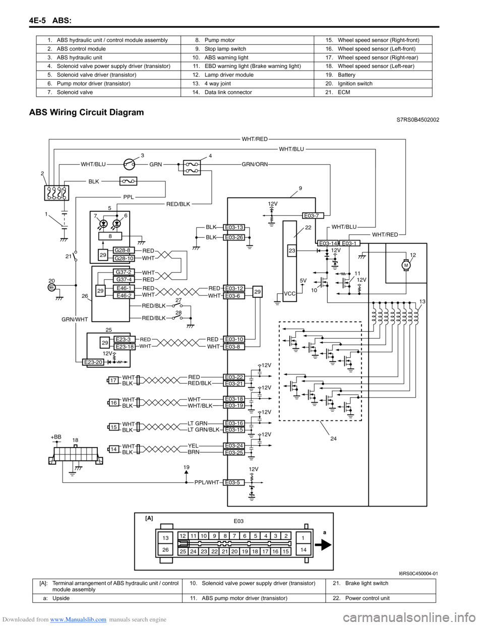
ABS Wiring Circuit DiagramS7RS0B4502002
1. ABS hydraulic unit / control module assembly 8.
Pump motor 15. Wheel speed sensor (Right-front)
2. ABS control module 9. Stop lamp switch 16. Wheel speed sensor (Left-front)
3. ABS hydraulic unit 10. ABS warning light 17. Wheel speed sensor (Right-rear)
4. Solenoid valve power supply driver (transistor) 11. EBD warnin g light (Brake warning light) 18. Wheel speed sensor (Left-rear)
5. Solenoid valve driver (transistor) 12. Lamp driver module 19. Battery
6. Pump motor driver (transistor) 13. 4 way joint 20. Ignition switch
7. Solenoid valve 14. Data link connector 21. ECM
[A]
14
1516171819202122232425 1
23456789101112
13
26 E03
a
WHT/BLU
BLKWHT/BLU
M
12V
9
10 11 12
13
BLKE03-14E03-1
E03-13
E03-26
YELBRN
14E03-24
LT GRN/BLKLT GRN
15
WHTWHT/BLK
16
RED
WHTBLK
WHTBLK
WHTBLK
WHTBLKRED/BLK
17
12V
PPL/WHT
18E03-5
1912V
5V
12V
23
24
VCC22
E03-25
E03-15E03-16
E03-19E03-18
E03-22E03-21
WHT/RED
WHT/RED
+BB
GRN/ORN
E03-7
WHT/BLUGRN
1
2
3
4
8
RED/BLK
E03-12
E03-6
RED
WHTE03-10E03-8
REDWHT
20 7
6
529
29
G28-8
G28-10
25
29
E23-3E23-18
GRN/WHT
21
PPL
12V
E23-20
12V
12V
12V
12V
REDWHTE46-1
E46-2
BLK
RED/BLK
RED/BLK
RED
RED
WHT
WHT
27
28
26
29
G37-2
G37-4
REDWHT
I6RS0C450004-01
[A]: Terminal arrangement of ABS hydraulic unit / control module assembly 10. Solenoid valve power supply driver
(transistor) 21. Brake light switch
a: Upside 11. ABS pump motor driver (transistor) 22. Power control unit
Page 545 of 1496
Downloaded from www.Manualslib.com manuals search engine ABS: 4E-6
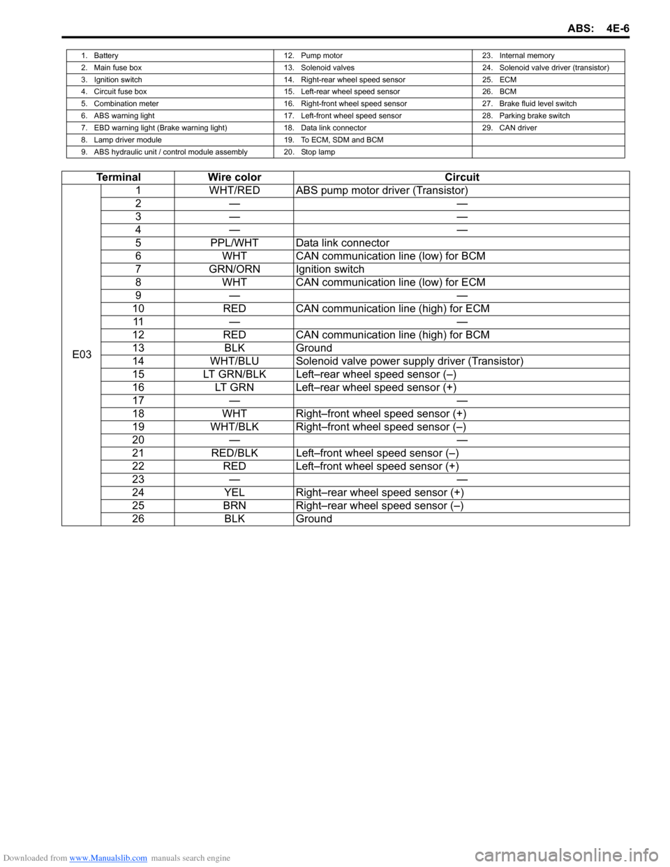
1. Battery12. Pump motor23. Internal memory
2. Main fuse box 13. Solenoid valves24. Solenoid valve driver (transistor)
3. Ignition switch 14. Right-rear wheel speed sensor25. ECM
4. Circuit fuse box 15. Left-rear wheel speed sensor26. BCM
5. Combination meter 16. Right-front wheel speed sensor27. Brake fluid level switch
6. ABS warning light 17. Left-front wheel speed sensor28. Parking brake switch
7. EBD warning light (Brake warning light) 18. Data link connector29. CAN driver
8. Lamp driver module 19. To ECM, SDM and BCM
9. ABS hydraulic unit / control module assembly 20. Stop lamp
Terminal Wire color Circuit
E03 1
WHT/RED ABS pump motor driver (Transistor)
2— —
3— —
4— —
5 PPL/WHT Data link connector
6 WHT CAN communication line (low) for BCM
7 GRN/ORN Ignition switch
8 WHT CAN communication line (low) for ECM
9— —
10 RED CAN communication line (high) for ECM
11 — —
12 RED CAN communication line (high) for BCM
13 BLK Ground
14 WHT/BLU Solenoid valve power supply driver (Transistor)
15 LT GRN/BLK Left–rear wheel speed sensor (–)
16 LT GRN Left–rear wheel speed sensor (+)
17 — —
18 WHT Right–front wheel speed sensor (+)
19 WHT/BLK Right–front wheel speed sensor (–)
20 — —
21 RED/BLK Left–front wheel speed sensor (–)
22 RED Left–front wheel speed sensor (+)
23 — —
24 YEL Right–rear wheel speed sensor (+)
25 BRN Right–rear wheel speed sensor (–)
26 BLK Ground
Page 546 of 1496

Downloaded from www.Manualslib.com manuals search engine 4E-7 ABS:
Component Location
ABS Components LocationS7RS0B4503001
Front Wheel Speed Sensor Components LocationS7RS0B4503002
14
5
3
2 2
2
2
6
6
6
6
7
8
I6RS0C450005-01
1. ABS hydraulic unit / control module assembly
5. EBD warning light (Brake warning light)
2. Wheel speed sensors 6. Wheel speed sensor rings
3. Stop lamp switch 7. Data link connector
4. ABS warning light 8. ECM
[A]
[B]
1 1
2
3
4
1
(a)
(b)
5I6RS0C450016-01
[A]: OK 2. Grommet5. Front wheel bearing
[B]: NG 3. Connector: 25 N⋅m (2.5 kgf-m, 18.0 lb-ft)
1. Front wheel speed sensor 4. Sensor ring: 11 N⋅m (1.1 kgf-m, 8.0 lb-ft)