2008 SUZUKI SWIFT Release arm
[x] Cancel search: Release armPage 147 of 1496
Downloaded from www.Manualslib.com manuals search engine Engine General Information and Diagnosis: 1A-97
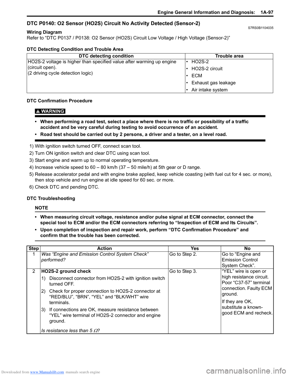
DTC P0140: O2 Sensor (HO2S) Circuit No Activity Detected (Sensor-2)S7RS0B1104035
Wiring Diagram
Refer to “DTC P0137 / P0138: O2 Sensor (HO2S) Circuit Low Voltage / High Voltage (Sensor-2)”
DTC Detecting Condition and Trouble Area
DTC Confirmation Procedure
WARNING!
• When performing a road test, select a place where there is no traffic or possibility of a traffic accident and be very careful during testing to avoid occurrence of an accident.
• Road test should be carried out by 2 persons, a driver and a tester, on a level road.
1) With ignition switch turned OFF, connect scan tool.
2) Turn ON ignition switch and clear DTC using scan tool.
3) Start engine and warm up to normal operating temperature.
4) Increase vehicle speed to 60 – 80 km/h (37 – 50 mile/h) at 5th gear or D range.
5) Release accelerator pedal and with engine brake applied, ke ep vehicle coasting (with fuel cut for 4 sec. or more),
then stop vehicle and run engine at idle speed for 60 sec. or more.
6) Check DTC and pending DTC.
DTC Troubleshooting
NOTE
• When measuring circuit voltage, resistance and/ or pulse signal at ECM connector, connect the
special tool to ECM and/or the ECM connectors re ferring to “Inspection of ECM and Its Circuits”.
• Upon completion of inspection and repair work, perform “DTC Confirmation Procedure” and confirm that the trouble has been corrected.
DTC detecting condition Trouble area
HO2S-2 voltage is higher than specified value after warming up engine
(circuit open).
(2 driving cycle detection logic) •HO2S-2
• HO2S-2 circuit
•ECM
• Exhaust gas leakage
• Air intake system
Step
Action YesNo
1 Was “Engine and Emission Control System Check”
performed? Go to Step 2.
Go to “Engine and
Emission Control
System Check”.
2 HO2S-2 ground check
1) Disconnect connector from HO 2S-2 with ignition switch
turned OFF.
2) Check for proper connection to HO2S-2 connector at “RED/BLU”, “BRN”, “YEL” and “BLK/WHT” wire
terminals.
3) If connections are OK, m easure resistance between
“YEL” wire terminal of HO2S-2 connector and engine
ground.
Is resistance less than 5
Ω? Go to Step 3. “YEL” wire is open or
high resistance circuit.
Poor “C37-57” terminal
connection. Faulty ECM
ground.
If they are OK,
substitute a known-
good ECM and recheck.
Page 167 of 1496
Downloaded from www.Manualslib.com manuals search engine Engine General Information and Diagnosis: 1A-117
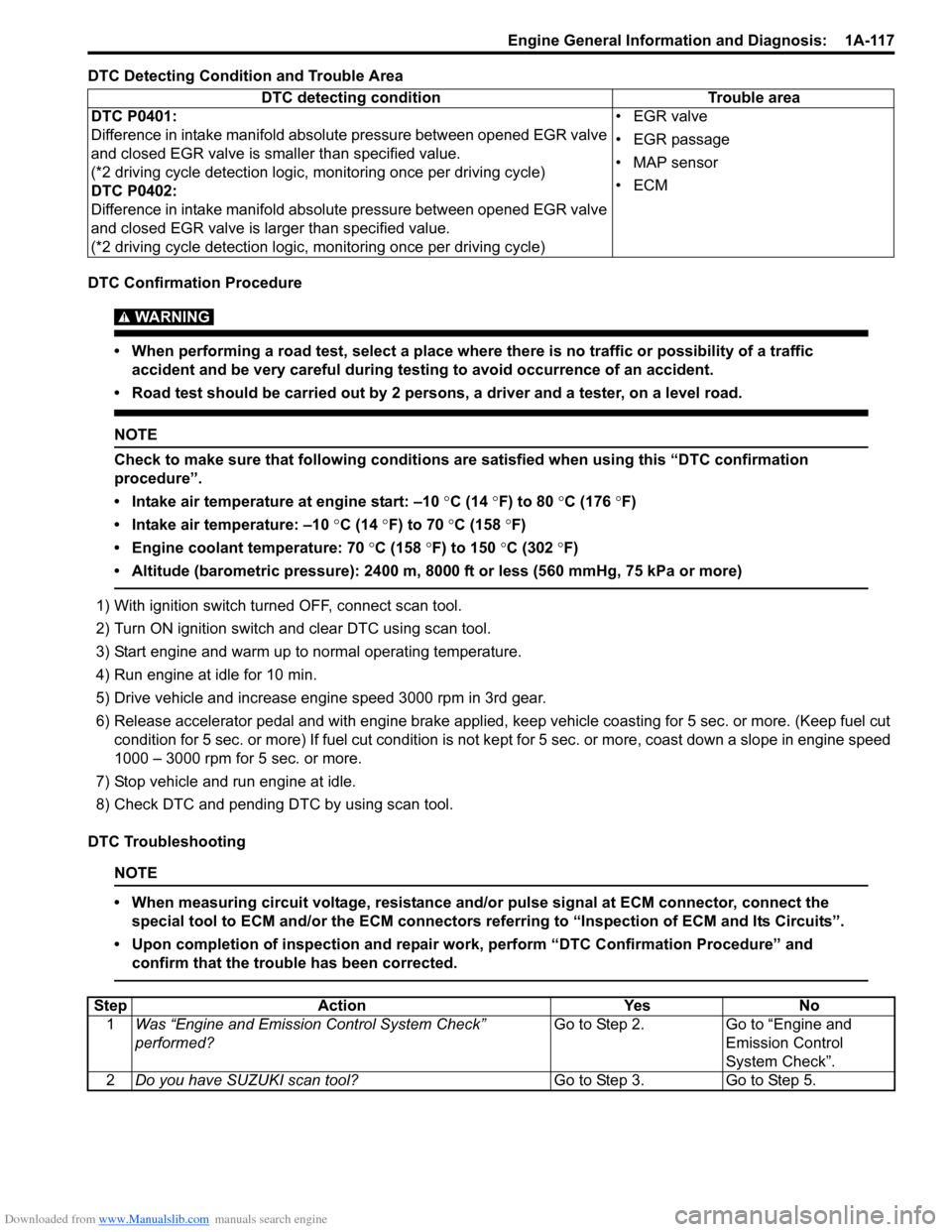
DTC Detecting Condition and Trouble Area
DTC Confirmation Procedure
WARNING!
• When performing a road test, select a place where there is no traffic or possibility of a traffic accident and be very careful during testing to avoid occurrence of an accident.
• Road test should be carried out by 2 persons, a driver and a tester, on a level road.
NOTE
Check to make sure that following conditions ar e satisfied when using this “DTC confirmation
procedure”.
• Intake air temperature at engine start: –10 °C (14 ° F) to 80 °C (176 °F)
• Intake air temperature: –10 °C (14 °F) to 70 °C (158 °F)
• Engine coolant temperature: 70 °C (158 °F) to 150 °C (302 °F)
• Altitude (barometric pressure): 2400 m, 8000 ft or less (560 mmHg, 75 kPa or more)
1) With ignition switch turned OFF, connect scan tool.
2) Turn ON ignition switch and clear DTC using scan tool.
3) Start engine and warm up to normal operating temperature.
4) Run engine at idle for 10 min.
5) Drive vehicle and increase engine speed 3000 rpm in 3rd gear.
6) Release accelerator pedal and with engine brake applied, keep vehicle coasting for 5 sec. or more. (Keep fuel cut condition for 5 sec. or more) If fuel cut condition is not ke pt for 5 sec. or more, coast down a slope in engine speed
1000 – 3000 rpm for 5 sec. or more.
7) Stop vehicle and run engine at idle.
8) Check DTC and pending DTC by using scan tool.
DTC Troubleshooting
NOTE
• When measuring circuit voltage, resistance and/ or pulse signal at ECM connector, connect the
special tool to ECM and/or the ECM connectors re ferring to “Inspection of ECM and Its Circuits”.
• Upon completion of inspection and repair work, perform “DTC Confirmation Procedure” and confirm that the trouble has been corrected.
DTC detecting condition Trouble area
DTC P0401:
Difference in intake manifold absolute pressure between opened EGR valve
and closed EGR valve is smaller than specified value.
(*2 driving cycle detection logic, monitoring once per driving cycle)
DTC P0402:
Difference in intake manifold absolute pressure between opened EGR valve
and closed EGR valve is la rger than specified value.
(*2 driving cycle detection logic, monitoring once per driving cycle) •EGR valve
• EGR passage
• MAP sensor
•ECM
Step
Action YesNo
1 Was “Engine and Emission Control System Check”
performed? Go to Step 2.
Go to “Engine and
Emission Control
System Check”.
2 Do you have SUZUKI scan tool? Go to Step 3.Go to Step 5.
Page 179 of 1496
Downloaded from www.Manualslib.com manuals search engine Engine General Information and Diagnosis: 1A-129
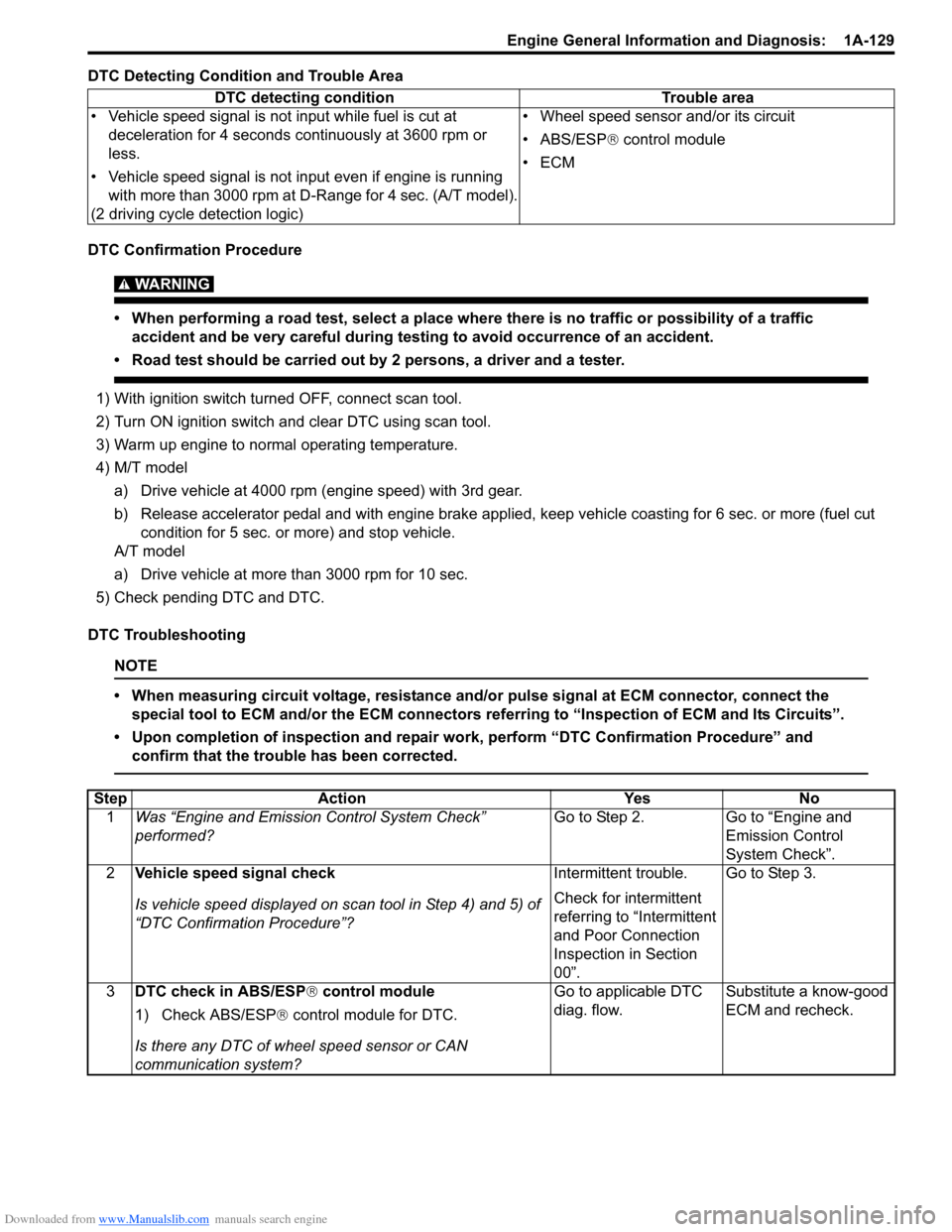
DTC Detecting Condition and Trouble Area
DTC Confirmation Procedure
WARNING!
• When performing a road test, select a place where there is no traffic or possibility of a traffic accident and be very careful during testing to avoid occurrence of an accident.
• Road test should be carried out by 2 persons, a driver and a tester.
1) With ignition switch turned OFF, connect scan tool.
2) Turn ON ignition switch and clear DTC using scan tool.
3) Warm up engine to normal operating temperature.
4) M/T model
a) Drive vehicle at 4000 rpm (e ngine speed) with 3rd gear.
b) Release accelerator pedal and with engine brake applied, keep vehicle coasting for 6 sec. or more (fuel cut condition for 5 sec. or more) and stop vehicle.
A/T model
a) Drive vehicle at more than 3000 rpm for 10 sec.
5) Check pending DTC and DTC.
DTC Troubleshooting
NOTE
• When measuring circuit voltage, resistance and/ or pulse signal at ECM connector, connect the
special tool to ECM and/or the ECM connectors re ferring to “Inspection of ECM and Its Circuits”.
• Upon completion of inspection and repair work, perform “DTC Confirmation Procedure” and confirm that the trouble has been corrected.
DTC detecting condition Trouble area
• Vehicle speed signal is not input while fuel is cut at deceleration for 4 seconds continuously at 3600 rpm or
less.
• Vehicle speed signal is not input even if engine is running with more than 3000 rpm at D-Range for 4 sec. (A/T model).
(2 driving cycle detection logic) • Wheel speed sensor and/or its circuit
• ABS/ESP®
control module
•ECM
Step Action YesNo
1 Was “Engine and Emission Control System Check”
performed? Go to Step 2.
Go to “Engine and
Emission Control
System Check”.
2 Vehicle speed signal check
Is vehicle speed displayed on scan tool in Step 4) and 5) of
“DTC Confirmation Procedure”? Intermittent trouble.
Check for intermittent
referring to “Intermittent
and Poor Connection
Inspection in Section
00”.Go to Step 3.
3 DTC check in ABS/ESP ® control module
1) Check ABS/ESP ® control module for DTC.
Is there any DTC of wheel speed sensor or CAN
communication system? Go to applicable DTC
diag. flow.
Substitute a know-good
ECM and recheck.
Page 378 of 1496
Downloaded from www.Manualslib.com manuals search engine 1G-3 Fuel System:
4) Check that battery voltage is 11 V or more.
5) Measure fuel pressure at each condition.If measured pressure is out of specification, refer to
“Fuel Pressure Check in Section 1A” and check each
possibly defective part. Replace if found defective.
a) Turn ignition switch ON to operate fuel pump and after 2 seconds turn it OFF. Repeat this 3 or 4
times and then check fuel pressure.
Fuel pressure specification
With fuel pump operating and engine
stopped: 270 – 310 kPa (2.7 – 3.1 kg/cm2, 38.4
– 44.0 psi)
b) Start engine and warm it up to normal operating temperature, and measure fuel pressure at
idling.
Fuel pressure specification
At specified idle speed: 270 – 310 kPa (2.7 –
3.1 kg/cm2, 38.4 – 44.0 psi)
c) Stop engine, and measure fuel pressure at one minute after stopping.
Fuel pressure specification
With 1 min. after engine (fuel pump) stop
(Pressure reduces as time passes): Over 300
kPa (3.0 kg/cm
2, 42.7 psi)
6) After checking fuel pressure, remove fuel pressure gauge.
WARNING!
As fuel feed line is still under high fuel
pressure, make sure to release fuel pressure
according to the following procedures.
• Place fuel container under joint.
• Cover joint with rag and loosen joint nut slowly in order to release fuel pressure
gradually.
7) Remove special tools from fuel delivery pipe and fuel feed hose.
8) Connect fuel feed hose to fuel delivery pipe and clamp it securely.
9) With engine OFF and ignition switch ON, check for fuel leaks.
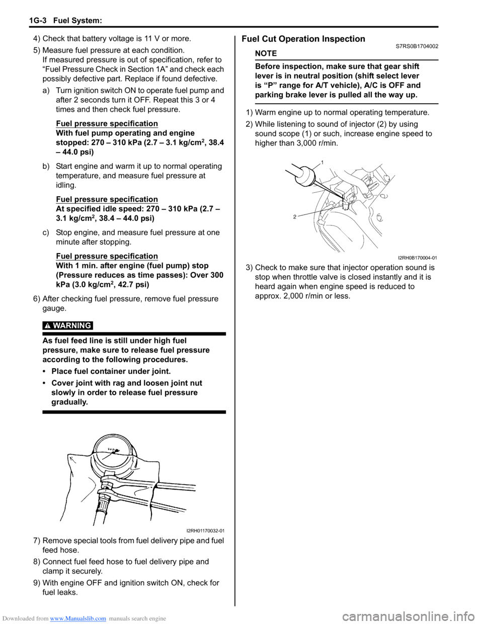
Fuel Cut Operation InspectionS7RS0B1704002
NOTE
Before inspection, make sure that gear shift
lever is in neutral positi on (shift select lever
is “P” range for A/T vehicle), A/C is OFF and
parking brake lever is pulled all the way up.
1) Warm engine up to normal operating temperature.
2) While listening to sound of injector (2) by using sound scope (1) or such, increase engine speed to
higher than 3,000 r/min.
3) Check to make sure that injector operation sound is stop when throttle valve is closed instantly and it is
heard again when engine speed is reduced to
approx. 2,000 r/min or less.
I2RH01170032-01
I2RH0B170004-01
Page 483 of 1496
Downloaded from www.Manualslib.com manuals search engine Drive Shaft / Axle: 3A-5
8) Disconnect front suspension control arm ball joint
stud from steering knuckle.
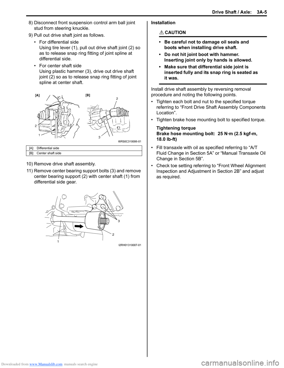
9) Pull out drive shaft joint as follows. • For differential sideUsing tire lever (1), pull out drive shaft joint (2) so
as to release snap ring fitting of joint spline at
differential side.
• For center shaft side Using plastic hammer (3), drive out drive shaft
joint (2) so as to release snap ring fitting of joint
spline at center shaft.
10) Remove drive shaft assembly. 11) Remove center bearing support bolts (3) and remove center bearing support (2) with center shaft (1) from
differential side gear. Installation
CAUTION!
• Be careful not to damage oil seals and
boots when installing drive shaft.
• Do not hit joint boot with hammer. Inserting joint only by hands is allowed.
• Make sure that differential side joint is inserted fully and its snap ring is seated as
it was.
Install drive shaft assemb ly by reversing removal
procedure and noting the following points.
• Tighten each bolt and nut to the specified torque referring to “Front Drive Shaft Assembly Components
Location”.
• Tighten brake hose mounting bolt to specified torque.
Tightening torque
Brake hose mounting bolt: 25 N·m (2.5 kgf-m,
18.0 lb-ft)
• Fill transaxle with oil as sp ecified referring to “A/T
Fluid Change in Section 5A” or “Manual Transaxle Oil
Change in Section 5B”.
• Check toe setting referring to “Front Wheel Alignment Inspection and Adjustment in Section 2B” and adjust
as required.
[A]: Differential side
[B]: Center shaft side
I6RS0C310006-01
3
2
1I2RH01310007-01
Page 652 of 1496
Downloaded from www.Manualslib.com manuals search engine 5A-8 Automatic Transmission/Transaxle:
Brake Interlock System ConstructionS7RS0B5101004
Shift Lock Solenoid Control
This system consists of shift lock solenoid control
system and interlock cable control system.
The shift lock solenoid cont rol system is so designed
that the select lever can not be shifted from “P” range
position unless ignition switch is turned to “ON” or “ACC”
position and the brake pedal is depressed.
And interlock cable control system is so designed that
select lever cannot be shifted from “P” range position
unless ignition switch is turned to “ACC” or “ON”
position. Also, ignition key cannot be pulled out of key
slot unless select le ver is in “P” range.
Shift Lock Solenoid Manual Release
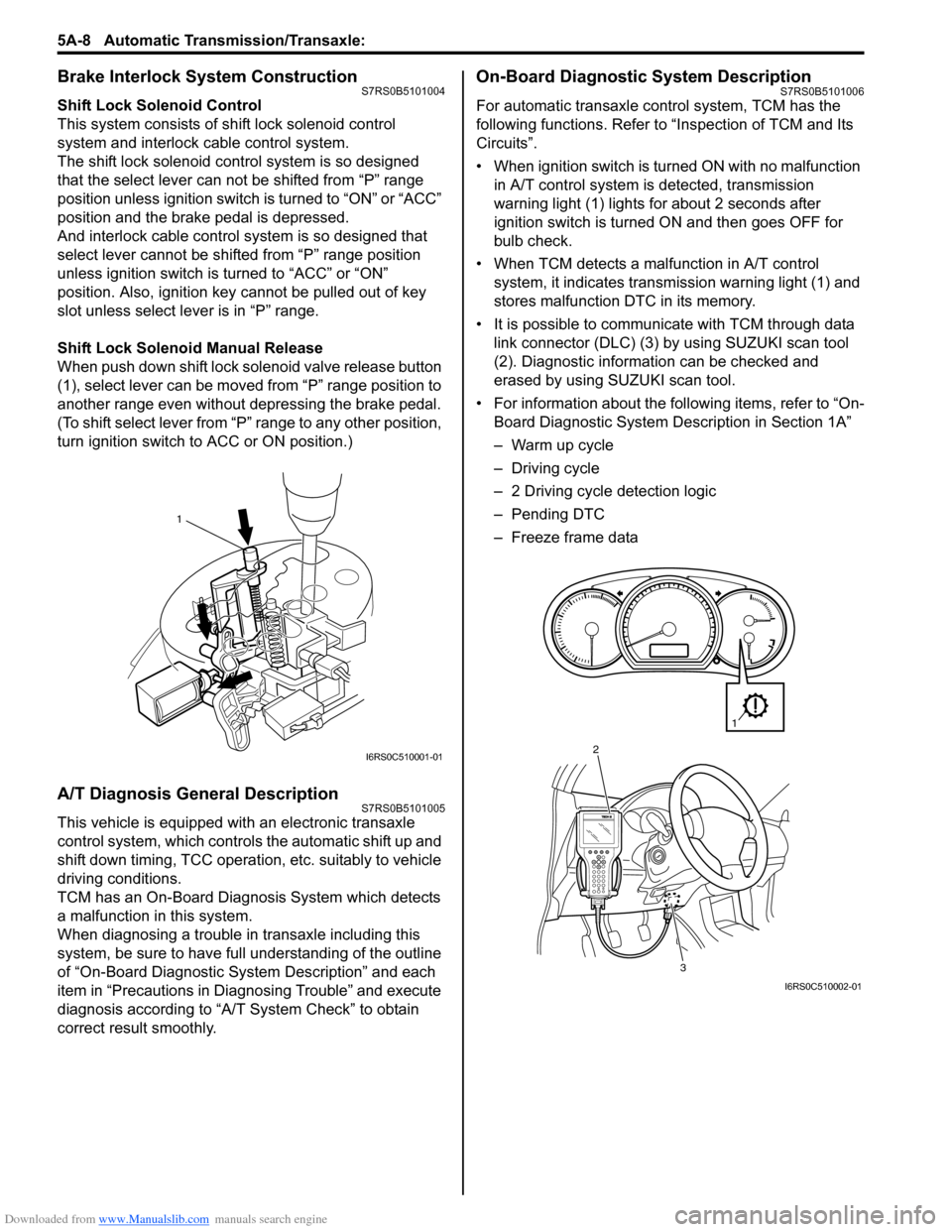
When push down shift lock solenoid valve release button
(1), select lever can be moved from “P” range position to
another range even without depressing the brake pedal.
(To shift select lever from “P” range to any other position,
turn ignition switch to ACC or ON position.)
A/T Diagnosis General DescriptionS7RS0B5101005
This vehicle is equipped with an electronic transaxle
control system, which controls the automatic shift up and
shift down timing, TCC operation, etc. suitably to vehicle
driving conditions.
TCM has an On-Board Diagnosis System which detects
a malfunction in this system.
When diagnosing a trouble in transaxle including this
system, be sure to have full understanding of the outline
of “On-Board Diagnostic System Description” and each
item in “Precautions in Diagnosing Trouble” and execute
diagnosis according to “A/T System Check” to obtain
correct result smoothly.
On-Board Diagnostic System DescriptionS7RS0B5101006
For automatic transaxle co ntrol system, TCM has the
following functions. Refer to “Inspection of TCM and Its
Circuits”.
• When ignition switch is turned ON with no malfunction in A/T control system is detected, transmission
warning light (1) lights for about 2 seconds after
ignition switch is turned ON and then goes OFF for
bulb check.
• When TCM detects a malfunction in A/T control system, it indicates transmission warning light (1) and
stores malfunction DTC in its memory.
• It is possible to communicate with TCM through data link connector (DLC) (3) by using SUZUKI scan tool
(2). Diagnostic information can be checked and
erased by using SUZUKI scan tool.
• For information about the following items, refer to “On- Board Diagnostic System De scription in Section 1A”
– Warm up cycle
– Driving cycle
– 2 Driving cycle detection logic
– Pending DTC
– Freeze frame data
1
I6RS0C510001-01
3
2
1
I6RS0C510002-01
Page 854 of 1496

Downloaded from www.Manualslib.com manuals search engine 5C-2 Clutch:
Diagnostic Information and Procedures
Clutch System Symptom DiagnosisS7RS0B5304001
Repair Instructions
Clutch Pedal InspectionS7RS0B5306001
Cylinder Push Rod Play “A”1) Press clutch pedal (1) gradually with finger, stop when slight increase of resistance is felt and
measure how much pedal has moved (push rod
play) as represented by “A” as shown.
Push rod play
“A”: Max. 3 mm (0.12 in.)
2) If “A” is not within specification, replace master cylinder (3) or pedal arm (2). Clutch Pedal Free Travel “B”
1) Depress clutch pedal (1), stop the moment clutch resistance is felt, and measure how much pedal has
moved (clutch pedal free travel) as represented by
“B” in figure.
Clutch pedal free travel
“B”
: 2 – 8 mm (0.08 – 0.31 in.)
2) If “B” is not within specification, check pedal arm (2) and master cylinder (3) and replace defective part.
Condition Possible cause Correction / Reference Item
Slipping Improper clutch pedal free travel Replace master cylinder or clutch pedal arm.
Worn or oily clutch disc facing Replace disc.
Warped disc, pressure plate or flywheel
surface Replace disc, clutch cover or flywheel.
Weakened diaphragm spring Replace clutch cover.
Master cylinder piston or seal cup not
returning Replace master cylinder.
Dragging clutch Improper clutch pedal free travel Replace master cylinder or clutch pedal arm.
Weakened diaphragm spring, or worn
spring tip Replace clutch cover.
Rusted input shaft splines Lubricate.
Damaged or worn splines of transaxle
input shaft Replace input shaft.
Excessively wobbly clutch disc Replace disc.
Clutch facings broken or dirty with oil Replace disc.
Fluid leakage Repair or replace.
Clutch vibration Glazed (glass-like) clutch facings Repair or replace disc.
Clutch facings dirty with oil Replace disc.
Release bearing slides unsmoothly on
input shaft bearing retainer Lubricate or replace input shaft bearing
retainer.
Wobbly clutch disc, or poor facing
contact Replace disc.
Weakened torsion springs in clutch disc Replace disc.
Clutch disc rivets loose Replace disc.
Distorted pressure plate or flywheel
surface Replace clutch cover or flywheel.
Weakened engine mounting Replace engine mounting.
Loosened engine mounting bolt or nut Retighten engine mounting bolt or nut.
Noisy clutch Worn or broken release bearing Replace release bearing.
Input shaft front bearing worn down Replace input shaft bearing.
Excessive rattle of clutch disc hub Replace disc.
Cracked clutch disc Replace disc.
Pressure plate and diaphragm spring
rattling Replace clutch cover.
Grabbing clutch Clutch disc facings soaked with oil Replace disc.
Clutch disc facings excessively worn Replace disc.
Rivet heads showing out of facing Replace disc.
Weakened torsion springs Replace disc.
Page 860 of 1496
Downloaded from www.Manualslib.com manuals search engine 5C-8 Clutch:
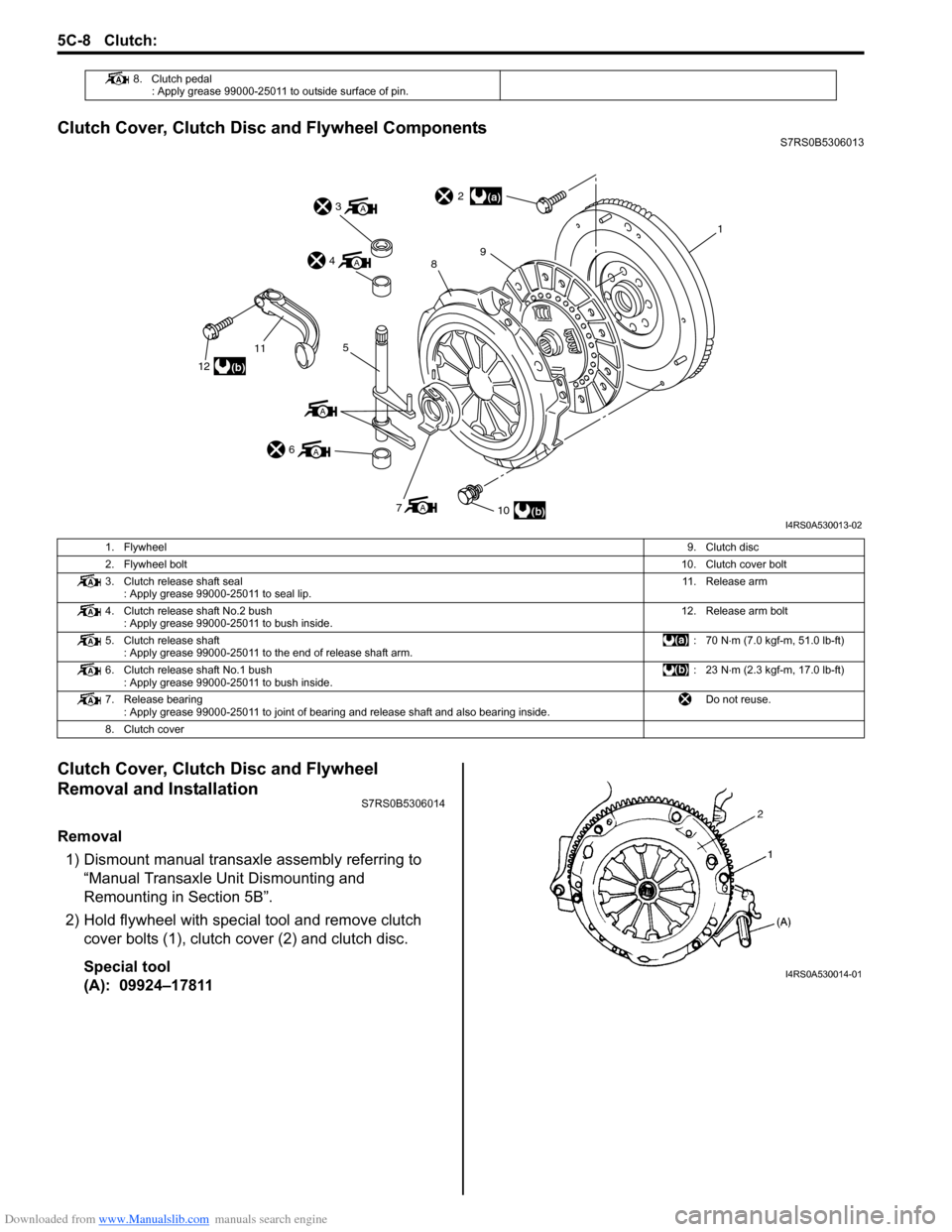
Clutch Cover, Clutch Disc and Flywheel ComponentsS7RS0B5306013
Clutch Cover, Clutch Disc and Flywheel
Removal and Installation
S7RS0B5306014
Removal1) Dismount manual transaxle assembly referring to “Manual Transaxle Unit Dismounting and
Remounting in Section 5B”.
2) Hold flywheel with specia l tool and remove clutch
cover bolts (1), clutch cover (2) and clutch disc.
Special tool
(A): 09924–17811
8. Clutch pedal : Apply grease 99000-25011 to outside surface of pin.
(a)
(b)
(b)
A
A
A
12
115
6
A3
A4
710
2
98
1
I4RS0A530013-02
1. Flywheel 9. Clutch disc
2. Flywheel bolt 10. Clutch cover bolt
3. Clutch release shaft seal : Apply grease 99000-25011 to seal lip. 11. Release arm
4. Clutch release shaft No.2 bush : Apply grease 99000-25011 to bush inside. 12. Release arm bolt
5. Clutch release shaft : Apply grease 99000-25011 to the end of release shaft arm. :70 N
⋅m (7.0 kgf-m, 51.0 lb-ft)
6. Clutch release shaft No.1 bush : Apply grease 99000-25011 to bush inside. :23 N
⋅m (2.3 kgf-m, 17.0 lb-ft)
7. Release bearing : Apply grease 99000-25011 to joint of bearing and release shaft and also bearing inside. Do not reuse.
8. Clutch cover
I4RS0A530014-01