2008 SUZUKI SWIFT Rear engine mounting
[x] Cancel search: Rear engine mountingPage 373 of 1496
Downloaded from www.Manualslib.com manuals search engine Engine Cooling System: 1F-10
Radiator Cooling Fan Removal and InstallationS7RS0B1606011
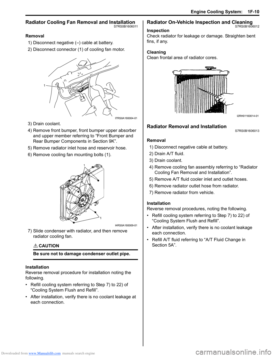
Removal1) Disconnect negative (–) cable at battery.
2) Disconnect connector (1) of cooling fan motor.
3) Drain coolant.
4) Remove front bumper, front bumper upper absorber and upper member referring to “Front Bumper and
Rear Bumper Componen ts in Section 9K”.
5) Remove radiator inlet hose and reservoir hose.
6) Remove cooling fan mounting bolts (1).
7) Slide condenser with radiator, and then remove radiator cooling fan.
CAUTION!
Be sure not to damage condenser outlet pipe.
Installation
Reverse removal procedure for installation noting the
following.
• Refill cooling system referring to Step 7) to 22) of “Cooling System Fl ush and Refill”.
• After installation, verify there is no coolant leakage at each connection.
Radiator On-Vehicle Inspection and CleaningS7RS0B1606012
Inspection
Check radiator for leakage or damage. Straighten bent
fins, if any.
Cleaning
Clean frontal area of radiator cores.
Radiator Removal and InstallationS7RS0B1606013
Removal
1) Disconnect negative cable at battery.
2) Drain A/T fluid.
3) Drain coolant.
4) Remove cooling fan assemb ly referring to “Radiator
Cooling Fan Removal and Installation”.
5) Remove A/T fluid cooler inlet and outlet hoses.
6) Remove radiator outlet hose from radiator.
7) Remove radiator from vehicle.
Installation
Reverse removal procedures, noting the following.
• Refill cooling system referrin g to Step 7) to 22) of
“Cooling System Flush and Refill”.
• After installation, verify there is no coolant leakage each connection.
• Refill A/T fluid referring to “A/T Fluid Change in
Section 5A”.
1
I7RS0A160004-01
I4RS0A160009-01
I2RH01160014-01
Page 432 of 1496
Downloaded from www.Manualslib.com manuals search engine 2A-1 Suspension General Diagnosis:
Suspension
Suspension General Diagnosis
Diagnostic Information and Procedures
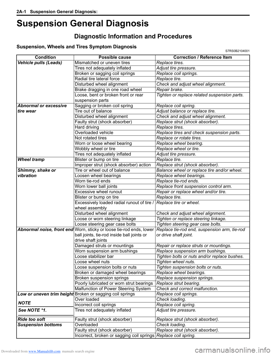
Suspension, Wheels and Tires Symptom DiagnosisS7RS0B2104001
ConditionPossible cause Correction / Reference Item
Vehicle pulls (Leads) Mismatched or uneven tires Replace tires.
Tires not adequately inflated Adjust tire pressure.
Broken or sagging coil springs Replace coil springs.
Radial tire lateral force Replace tire.
Disturbed wheel alignment Check and adjust wheel alignment.
Brake dragging in one road wheel Repair brake.
Loose, bent or broken front or rear
suspension parts Tighten or replace related suspension parts.
Abnormal or excessive
tire wear Sagging or broken coil spring
Replace coil spring.
Tire out of balance Adjust balance or replace tire.
Disturbed wheel alignment Check and adjust wheel alignment.
Faulty strut (shock absorber) Replace strut (shock absorber).
Hard driving Replace tires.
Overloaded vehicle Replace tires and check suspension parts.
Not rotated tires Replace or rotate tires.
Worn or loose wheel bearing Replace wheel bearing.
Wobbly wheel or tire Replace wheel or tire.
Tires not adequately inflated Adjust tire pressure.
Wheel tramp Blister or bump on tire Replace tire.
Improper strut (shock absorber) action Replace strut (shock absorber).
Shimmy, shake or
vibration Tire or wheel out of balance
Balance wheel or replace tire and/or wheel.
Loosen wheel bearings Replace wheel bearings.
Worn tie-rod ends Replace tie-rod ends.
Worn lower ball joints Replace front suspension control arm.
Excessive wheel runout Repair or replace wheel and/or tire.
Blister or bump on tire Replace tire.
Excessively loaded radial runout of tire /
wheel assembly Replace tire or wheel.
Disturbed wheel alignment Check and adjust wheel alignment.
Loose or worn steering linkage Tighten or replace steering linkage.
Loose steering gear case bolts Tighten steering gear case bolts.
Abnormal noise, front end Worn, sticky or loose tie-rod ends, lower
ball joints, tie-rod in side ball joints or
drive shaft joints Replace tie-rod end, su
spension arm, tie-rod
or drive shaft joint.
Damaged struts or mountings Repair or replace struts or mountings.
Worn suspension arm bushings Replace suspension arm bushings.
Loose stabilizer bar Tighten bolts or nuts and/or replace bushes.
Loose wheel nuts Tighten wheel nuts.
Loose suspension bolts or nuts Tighten suspension bolts or nuts.
Broken or damaged wheel bearings Replace wheel bearings.
Broken suspension springs Replace suspension springs.
Poorly lubricated or worn strut bearings Replace strut bearing.
Malfunction of Power Steering System Check and correct malfunction.
Low or uneven trim height
NOTE
See NOTE *1.
Broken or sagging coil springs Replace coil springs.
Over loaded Check loading.
Incorrect coil springs Replace coil spring.
Tires not adequately inflated Adjust tire pressure.
Ride too soft Faulty strut (shock absorber) Replace strut (shock absorber).
Suspension bottoms Overloaded Check loading.
Faulty strut (shock absorber) Replace strut (shock absorber).
Incorrect, broken or sagging coil springs Replace coil spring.
Page 433 of 1496
Downloaded from www.Manualslib.com manuals search engine Suspension General Diagnosis: 2A-2
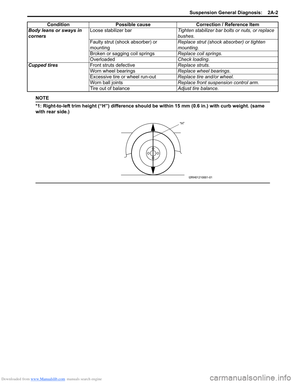
NOTE
*1: Right-to-left trim height (“H”) difference should be within 15 mm (0.6 in.) with curb weight. (same
with rear side.)
Body leans or sways in
corners Loose stabilizer bar
Tighten stabilizer bar bolts or nuts, or replace
bushes.
Faulty strut (shock absorber) or
mounting Replace strut (shock absorber) or tighten
mounting.
Broken or sagging coil springs Replace coil springs.
Overloaded Check loading.
Cupped tires Front struts defective Replace struts.
Worn wheel bearings Replace wheel bearings.
Excessive tire or wheel run-out Replace tire and/or wheel.
Worn ball joints Replace front suspension control arm.
Tire out of balance Adjust tire balance.
Condition Possible cause Correction / Reference Item
“H”
I2RH01210001-01
Page 446 of 1496
Downloaded from www.Manualslib.com manuals search engine 2B-13 Front Suspension:
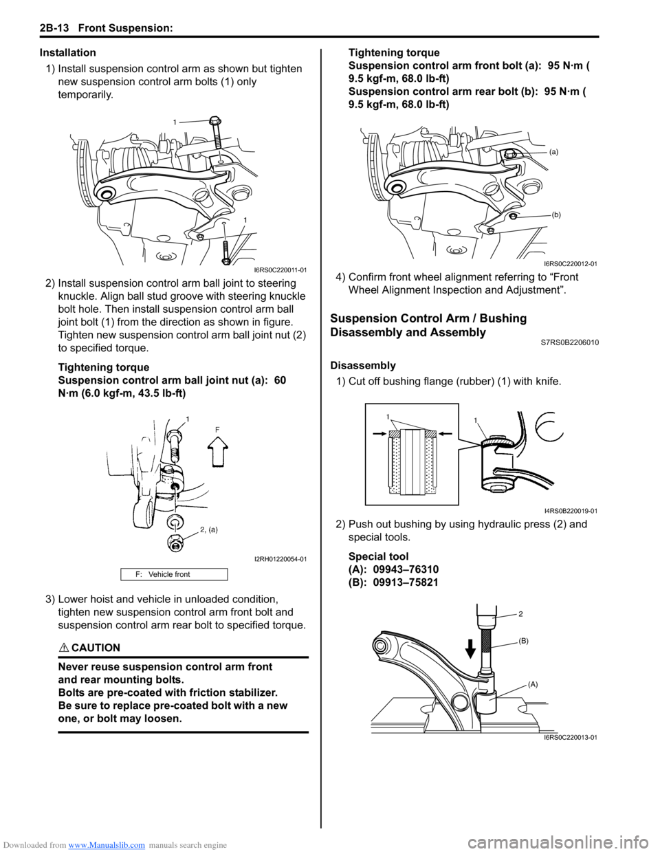
Installation1) Install suspension control arm as shown but tighten new suspension contro l arm bolts (1) only
temporarily.
2) Install suspensi on control arm ball joint to steering
knuckle. Align ball stud gr oove with steering knuckle
bolt hole. Then install su spension control arm ball
joint bolt (1) from the direction as shown in figure.
Tighten new suspension cont rol arm ball joint nut (2)
to specified torque.
Tightening torque
Suspension control arm ball joint nut (a): 60
N·m (6.0 kgf-m, 43.5 lb-ft)
3) Lower hoist and vehicle in unloaded condition, tighten new suspension control arm front bolt and
suspension control arm rear bolt to specified torque.
CAUTION!
Never reuse suspension control arm front
and rear mounting bolts.
Bolts are pre-coated with friction stabilizer.
Be sure to replace pre-coated bolt with a new
one, or bolt may loosen.
Tightening torque
Suspension control arm front bolt (a): 95 N·m (
9.5 kgf-m, 68.0 lb-ft)
Suspension control arm re ar bolt (b): 95 N·m (
9.5 kgf-m, 68.0 lb-ft)
4) Confirm front wheel alignment referring to “Front Wheel Alignment Inspection and Adjustment”.
Suspension Control Arm / Bushing
Disassembly and Assembly
S7RS0B2206010
Disassembly
1) Cut off bushing flange (rubber) (1) with knife.
2) Push out bushing by using hydraulic press (2) and special tools.
Special tool
(A): 09943–76310
(B): 09913–75821
F: Vehicle front
1
1
I6RS0C220011-01
I2RH01220054-01
(a)(b)
I6RS0C220012-01
I4RS0B220019-01
2
(A)
(B)
I6RS0C220013-01
Page 449 of 1496
Downloaded from www.Manualslib.com manuals search engine Front Suspension: 2B-16
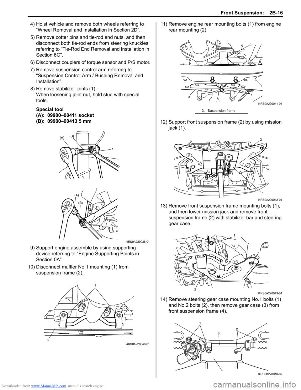
4) Hoist vehicle and remove both wheels referring to “Wheel Removal and Installation in Section 2D”.
5) Remove cotter pins and tie-rod end nuts, and then disconnect both tie-rod ends from steering knuckles
referring to “Tie-Rod End Re moval and Installation in
Section 6C”.
6) Disconnect couplers of torque sensor and P/S motor.
7) Remove suspension control arm referring to “Suspension Control Arm / Bushing Removal and
Installation”.
8) Remove stabilizer joints (1). When loosening joint nu t, hold stud with special
tools.
Special tool
(A): 09900–00411 socket
(B): 09900–00413 5 mm
9) Support engine assemble by using supporting device referring to “Engine Supporting Points in
Section 0A”.
10) Disconnect muffler No.1 mounting (1) from suspension frame (2). 11) Remove engine rear mounting bolts (1) from engine
rear mounting (2).
12) Support front suspension frame (2) by using mission jack (1).
13) Remove front suspension frame mounting bolts (1), and then lower mission jack and remove front
suspension frame (2) with st abilizer bar and steering
gear case.
14) Remove steering gear case mounting No.1 bolts (1) and No.2 bolts (2), then remove gear case (3) from
front suspensio n frame (4).
11
(A)
(A)
(B)
(B)
I4RS0A220038-01
1
2
I4RS0A220040-01
3. Suspension frame
2
3 1
I4RS0A220041-01
2
1
I4RS0A220042-01
1
2 1
I4RS0A220043-01
1
3
4 2
I4RS0B220010-02
Page 451 of 1496

Downloaded from www.Manualslib.com manuals search engine Front Suspension: 2B-18
7) Tighten front suspension frame mounting bolts (a) to specified torque.
Tightening torque
Front suspension frame mounting bolt (a): 150
N·m (15.0 kgf-m, 108.5 lb-ft)
8) Lower mission jack.
9) Tighten engine rear mounting bolts (a) to specified torque.
Tightening torque
Engine rear mounting bolt (a): 55 N·m (5.5 kgf-
m, 40.0 lb-ft)
10) Connect muffler No.1 mounting (1) to front suspension frame (2). 11) Remove supporting device from engine.
12) Install stabilizer joints (1), and tighten nuts to
specified torque.
When tightening, hold stud with special tools.
Special tool
(A): 09900–00411 socket
(B): 09900–00413 5 mm
Tightening torque
Stabilizer joint nut (a): 50 N·m (5.0 kgf-m, 36.5
lb-ft)
2. Engine rear mounting 3. Suspension frame
(a)
(a)
I4RS0A220048-01
2
3 (a)
I4RS0A220049-01
1
2
I4RS0A220040-01
1 1
(A)
(A)
(a) (a)
(B)
(B)
I4RS0A220051-01
Page 453 of 1496

Downloaded from www.Manualslib.com manuals search engine Front Suspension: 2B-20
Specifications
Tightening Torque SpecificationsS7RS0B2207001
NOTE
The specified tightening torque is also described in the following.
“Front Suspension Construction”
“Front Strut Assembly Components”
“Front Wheel Hub and Steering Knuckle Components”
“Front Suspension Frame, Stabilizer Bar and/or Bushings Components”
Reference:
For the tightening torque of fastener not specified in this section, refer to “Fasteners Information in Section 0A”.
Fastening part
Tightening torque
Note
N ⋅mkgf-mlb-ft
Tie-rod end lock nut 454.5 32.5 �)
Strut bracket nut 909.0 65.5 �) / �)
Brake hose mounting bolt 252.5 18.0 �)
Stabilizer joint nut 505.0 36.5 �) / �)
Strut nut 505.0 36.5 �)
Wheel nut 858.5 61.5 �) / �) / �)
Strut support lower nut 505.0 36.5 �)
Suspension control arm ball joint nut 606.0 43.5 �) / �)
Wheel speed sensor mounting bolt 111.1 8.0 �)
Caliper carrier bolt 858.5 61.5 �)
Drive shaft nut 200 20.0 145.0�)
Suspension control arm front bolt 959.5 68.0 �)
Suspension control arm rear bolt 959.5 68.0 �)
Stabilizer bar mounting bracket bolt 232.3 17.0 �)
Steering gear case mounting No.1 bolt 555.5 40.0 �)
Steering gear case mounting No.2 bolt 555.5 40.0 �)
Front suspension frame mounting bolt 150 15.0 108.5�)
Engine rear mounting bolt 555.5 40.0 �)
Steering shaft joint bolt 252.5 18.5 �)
Wheel bolt 858.5 61.5 �)
Page 503 of 1496
Downloaded from www.Manualslib.com manuals search engine Brake Control System and Diagnosis: 4A-5
If deterioration of rubber is evident, disassemble all
hydraulic parts and wash with alcohol. Dry these parts
with compressed air before assembly to keep alcohol out
of the system. Replace all rubber parts in the system,
including hoses. Also, when working on the brake
mechanisms, check for fluid on the linings.
If excessive fluid is found, replace the pads. If master cylinder piston seals
are satisfactory, check for
leakage or excessive heat co nditions. If leakage is not
found, drain fluid, flush with brake fluid, refill and bleed
system.
The system must be flushed if there is any doubt as to
the grade of fluid in the system or if fluid has been used
which contained parts that have been subjected to
contaminated fluid.
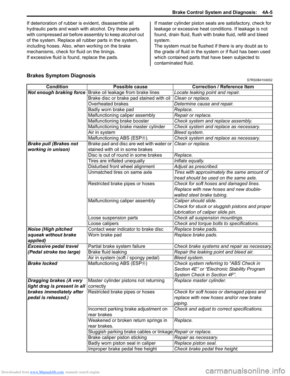
Brakes Symptom DiagnosisS7RS0B4104002
Condition Possible cause Correction / Reference Item
Not enough braking force Brake oil leakage from brake lines Locate leaking point and repair.
Brake disc or brake pad stained with oil Clean or replace.
Overheated brakes Determine cause and repair.
Badly worn brake pad Replace.
Malfunctioning caliper assembly Repair or replace.
Malfunctioning brake booster Check system and replace assembly.
Malfunctioning brake master cylinder Check system and replace as necessary.
Air in system Bleed system.
Malfunctioning ABS (ESP ®). Check system and replace as necessary.
Brake pull (Brakes not
working in unison) Brake pad and disc are wet with water or
stained with oil in some brakes Clean or replace.
Disc is out of round in some brakes Replace.
Tires are inflated unequally Inflate equally.
Disturbed front wheel alignment Adjust as prescribed.
Unmatched tires on same axle Tires with approximately the same amount of
tread should be used on the same axle.
Restricted brake pipes or hoses Check for soft hoses and damaged lines.
Replace with new hoses and new double-
walled steel brake tubing.
Malfunctioning caliper assembly Caliper should slide.
Check for stuck or sluggish pistons and proper
lubrication of caliper slide pin.
Loose suspension parts Check all suspension mountings.
Loose calipers Check and torque bolts to specifications.
Noise (High pitched
squeak without brake
applied) Contact wear indicator to brake disc
Replace brake pads.
Worn brake pad Replace brake pads.
Excessive pedal travel
(Pedal stroke too large) Partial brake system failure
Check brake systems and repair as necessary.
Brake fluid leaking Repair the leaking point and bleed air.
Air in system (soft / spongy pedal) Bleed system.
Brake locked Malfunctioning ABS (ESP®) Check system referri ng to “ABS Check in
Section 4E” or “Electronic Stability Program
System Check in Section 4F”.
Dragging brakes (A very
light drag is present in all
brakes immediately after
pedal is released.) Master cylinder pistons not returning
correctly
Replace master cylinder.
Restricted brake pipes or hoses Check for soft hoses or damaged pipes and
replace with new hoses and/or new brake
piping.
Incorrect parking brake adjustment on
rear brakes Check and adjust to correct specifications.
Weakened or broken return springs in
rear brakes. Replace.
Sluggish parking brake cables or linkage Repair or replace.
Brake caliper piston sticking Repair as necessary.
Badly worn piston seal in caliper Replace piston seal.
Improper brake pedal free height Check brake pedal free height.