2008 SUZUKI SWIFT Lining
[x] Cancel search: LiningPage 777 of 1496
Downloaded from www.Manualslib.com manuals search engine Automatic Transmission/Transaxle: 5A-133
Forward and Reverse Clutch Assembly
Inspection
S7RS0B5106044
Clutch, Discs, Separator Plates and Retaining Plate
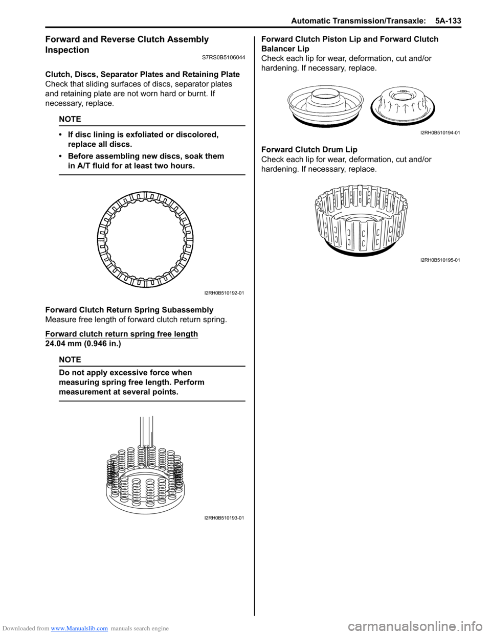
Check that sliding surfaces of discs, separator plates
and retaining plate are not worn hard or burnt. If
necessary, replace.
NOTE
• If disc lining is exfoliated or discolored, replace all discs.
• Before assembling new discs, soak them in A/T fluid for at least two hours.
Forward Clutch Return Spring Subassembly
Measure free length of fo rward clutch return spring.
Forward clutch return spring free length
24.04 mm (0.946 in.)
NOTE
Do not apply excessive force when
measuring spring free length. Perform
measurement at several points.
Forward Clutch Piston Lip and Forward Clutch
Balancer Lip
Check each lip for wear, deformation, cut and/or
hardening. If necessary, replace.
Forward Clutch Drum Lip
Check each lip for wear, deformation, cut and/or
hardening. If necessary, replace.
I2RH0B510192-01
I2RH0B510193-01
I2RH0B510194-01
I2RH0B510195-01
Page 791 of 1496

Downloaded from www.Manualslib.com manuals search engine Automatic Transmission/Transaxle: 5A-147
3) Install new differential side oil seal to transaxle case by using special tools.
Special tool
(A): 09924–74510
(B): 09944–88220
Differential side oil seal installing depth
“a”: 3.8 – 4.8 mm (0.15 – 0.19 in.)
4) Apply grease to oil seal lip. : Grease 99000–25030 (SUZUKI Super Grease C)
Automatic Transaxle Unit Inspection and
Adjustment
S7RS0B5106059
Inspection
Brake discs
Dry and inspect them for pitting, burn flaking, significant
wear, glazing, cracking, charring and chips or metal
particles imbedded in lining.
If discs show any of the ab ove conditions, replacement
is required.
NOTE
• If disc lining is exfoliated or discolored, replace all discs.
• Before assembling new discs, soak them in A/T fluid for at least two hours.
Brake separator plates and retaining plates
Dry plates and check for discol oration. If plate surface is
smooth and even color smear is indicated, plate should
be reused. If severe heat spot discoloration or surface
scuffing is indicated, plate must be replaced.
Brake return spring subassembly
Measure free length of each brake return spring
subassembly.
Evidence of extreme heat or burning in the area of clutch
may have caused springs to take heat set and would
require their replacement.
Free length of 1st & reverse brake return spring
subassembly
“a”: 21.71 mm (0.855 in.)
Free length of 2nd brake return spring subassembly
“a”: 15.85 mm (0.624 in.)
NOTE
• Do not apply excessive force when measuring spring free length.
• Perform measurement at several points.
I2RH0B510252-01
I2RH01510147-01
I2RH0B510253-01
I2RH0B510173-01
Page 1136 of 1496
Downloaded from www.Manualslib.com manuals search engine 8B-98 Air Bag System:
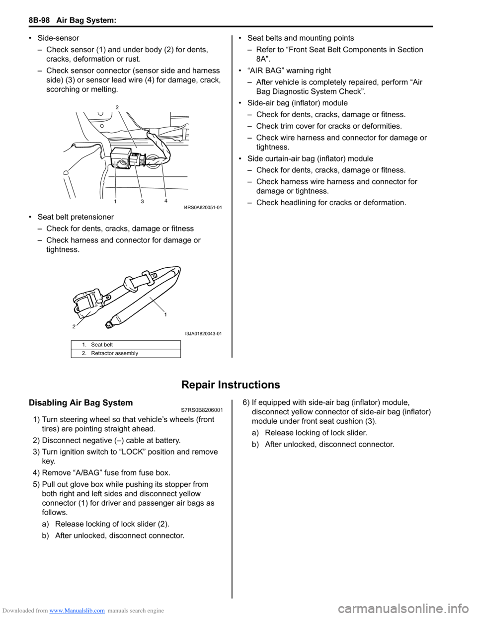
• Side-sensor– Check sensor (1) and under body (2) for dents, cracks, deformation or rust.
– Check sensor connector (sensor side and harness side) (3) or sensor lead wire (4) for damage, crack,
scorching or melting.
• Seat belt pretensioner – Check for dents, cracks , damage or fitness
– Check harness and connector for damage or tightness. • Seat belts and mounting points
– Refer to “Front Seat Belt Components in Section 8A”.
• “AIR BAG” warning right
– After vehicle is completely repaired, perform “Air Bag Diagnostic System Check”.
• Side-air bag (inflator) module – Check for dents, cra cks, damage or fitness.
– Check trim cover for cracks or deformities.
– Check wire harness and connector for damage or tightness.
• Side curtain-air bag (inflator) module – Check for dents, cra cks, damage or fitness.
– Check harness wire harness and connector for damage or tightness.
– Check headlining for cracks or deformation.
Repair Instructions
Disabling Air Bag SystemS7RS0B8206001
1) Turn steering wheel so that vehicle’s wheels (front tires) are pointing straight ahead.
2) Disconnect negative (–) cable at battery.
3) Turn ignition switch to “LOCK” position and remove key.
4) Remove “A/BAG” fu se from fuse box.
5) Pull out glove box while pushing its stopper from
both right and left sides and disconnect yellow
connector (1) for driver and passenger air bags as
follows.
a) Release locking of lock slider (2).
b) After unlocked, disconnect connector. 6) If equipped with side-air bag (inflator) module,
disconnect yellow connector of side-air bag (inflator)
module under front seat cushion (3).
a) Release locking of lock slider.
b) After unlocked, disconnect connector.
1. Seat belt
2. Retractor assembly
13 4
2I4RS0A820051-01
I3JA01820043-01
Page 1145 of 1496
Downloaded from www.Manualslib.com manuals search engine Air Bag System: 8B-107
Side-Air Bag (Inflator) InspectionS7RS0B8206010
WARNING!
• Never attempt to disassemble or repair the side-air bag (inflator) module. If any
abnormality is found, be sure to replace it
with new one as an assembly.
• Be sure to read “Precautions on Service and Diagnosis of Air Bag System” before
starting to work and observe every
precaution during work. Neglecting them
may result in personal injury or
undeployment of the air bag when
necessary.
CAUTION!
If air bag (inflator) module was dropped from
a height of 90 cm (3 ft) or more, it should be
replaced.
Check air bag (inflator) module appearance visually for
the following symptoms and if any one of them is found,
replace with a new one.
• Air bag has deployed.
• There is a crack in trim cover (pad surface).
• Wire harness or connector is damaged.
• Air bag (inflator) module is damaged or a strong impact was applied to it.
• Bend or deformity of air bag (inflator) module bracket.
Side Curtain-Air Bag (Inflator) Module Removal
and Installation
S7RS0B8206011
WARNING!
• Never attempt to disassemble or repair the side curtain-air bag (inflator) module. If any
abnormality is found, be sure to replace it
with new one as an assembly.
• Be sure to read “Precautions on Service and Diagnosis of Air Bag System”,
“Precautions on Handling and Storage of
Air Bag System Components” and
“Precautions on Disposal of Air Bag and
Seat Belt Pretensioner” before starting to
work and observe every precaution during
work. Neglecting them may result in
personal injury or undeployment of the air
bag when necessary.
Removal
1) Disable air bag system. Re fer to “Disabling Air Bag
System”.
2) Remove head lining referring to “Head Lining Removal and Installati on in Section 9H”.
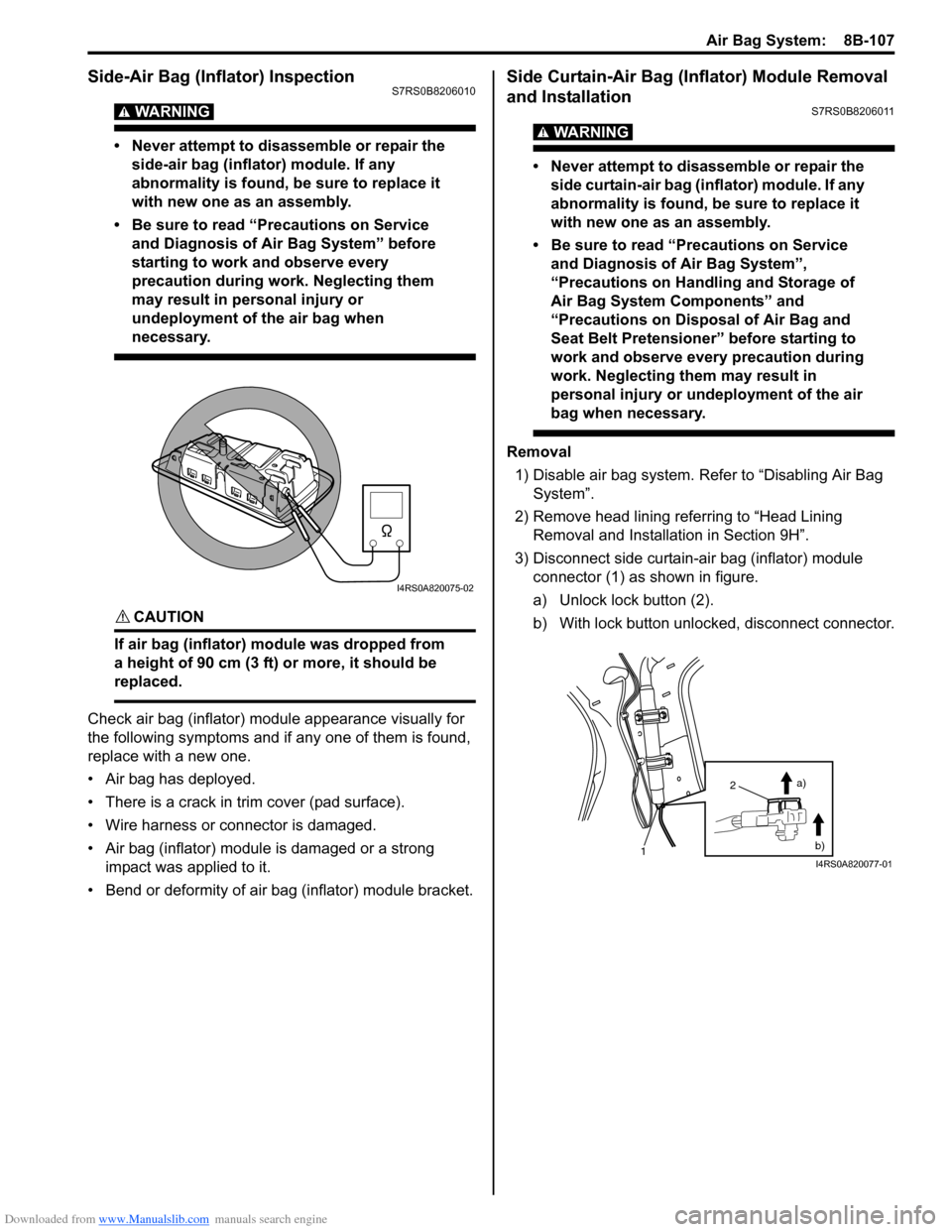
3) Disconnect side curtain-air bag (inflator) module connector (1) as shown in figure.
a) Unlock lock button (2).
b) With lock button unlocked, disconnect connector.
I4RS0A820075-02
2
1 a)
b)
I4RS0A820077-01
Page 1146 of 1496
Downloaded from www.Manualslib.com manuals search engine 8B-108 Air Bag System:
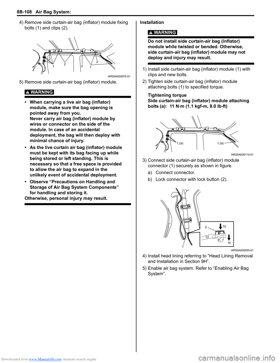
4) Remove side curtain-air bag (inflator) module fixing bolts (1) and clips (2).
5) Remove side curtain-air bag (inflator) module.
WARNING!
• When carrying a live air bag (inflator) module, make sure the bag opening is
pointed away from you.
Never carry air bag (inflator) module by
wires or connector on the side of the
module. In case of an accidental
deployment, the bag will then deploy with
minimal chance of injury.
• As the live curtain air bag (inflator) module must be kept with it s bag facing up while
being stored or left standing. This is
necessary so that a free space is provided
to allow the air bag to expand in the
unlikely event of accidental deployment.
• Observe “Precautions on Handling and Storage of Air Bag System Components”
for handling and storing it.
Otherwise, personal injury may result.
Installation
WARNING!
Do not install side curtain-air bag (inflator)
module while twisted or bended. Otherwise,
side curtain-air bag (inflator) module may not
deploy and injury may result.
1) Install side curtain-air bag (inflator) module (1) with
clips and new bolts.
2) Tighten side curtain-air bag (inflator) module attaching bolts (1) to specified torque.
Tightening torque
Side curtain-air bag (inflator) module attaching
bolts (a): 11 N·m (1.1 kgf-m, 8.0 lb-ft)
3) Connect side curtain-air bag (inflator) module connector (1) securely as shown in figure.
a) Connect connector.
b) Lock connector wi th lock button (2).
4) Install head lining referring to “Head Lining Removal and Installation in Section 9H”.
5) Enable air bag system. Refer to “Enabling Air Bag System”.1 2
2
22
1
I4RS0A820076-01
1,(a) 1,(a)
I4RS0A820110-01
1
2
a)
b)
I4RS0A820055-01
Page 1170 of 1496

Downloaded from www.Manualslib.com manuals search engine 9-iv Table of Contents
Rear End Door Opener System Symptom Diagnosis .......................................................... 9F-5
Rear End Door Opener System Operation Inspection .......................................................... 9F-5
Repair Instructions ........... ................................... 9F-6
Front Door Lock Assembly Components ............ 9F-6
Front Door Lock Assembly Removal and Installation ......................................................... 9F-6
Front Door Lock Assembly Inspection ................ 9F-8
Power Door Lock Switch In spection.................... 9F-8
Door Key Cylinder Switch Inspection .................. 9F-8
Power Door Lock Actuator Inspection ................. 9F-9
Rear Door Lock Assembly Components ........... 9F-10
Rear Door Lock Assembly Removal and Installation ....................................................... 9F-10
Rear Door Lock Assembly Inspection ............... 9F-10
Rear End Door Lock Assembly Components.... 9F-11
Rear End Door Lock Assembly Removal and Installation ....................................................... 9F-11
Rear End Door Lock Assembly Inspection........ 9F-12
Rear End Door Opener Switch Inspection ........ 9F-12
Replacement of Transmitte r Battery ................. 9F-13
Programming Transmitter Code for Keyless Entry System (Vehicle without Keyless Start
System) ........................................................... 9F-13
Keyless Entry Answer Back Function
Change-over Procedure (If Equipped) ............ 9F-14
Keyless Entry Receiver Removal and
Installation ....................................................... 9F-14
Keyless Entry Receiver and Its Circuit Inspection ........................................................ 9F-15
Specifications .... ................................................. 9F-16
Tightening Torque Specifications ...................... 9F-16
Special Tools and Equipmen t ........................... 9F-16
Recommended Service Material ....................... 9F-16
Seats ............. ............................................ 9G-1
Repair Instructions ............................................. 9G-1
Front Seat Components ..................................... 9G-1
Front Seat Removal and In stallation .................. 9G-2
Rear Seat Components...................................... 9G-3
Rear Seat Removal and Installation................... 9G-4
Specifications .... .................................................. 9G-4
Tightening Torque Specifications ....................... 9G-4
Special Tools and Equipmen t ............................ 9G-4
Recommended Service Material ........................ 9G-4
Interior Trim ................. ............................ 9H-1
Repair Instructions ............ ..................................9H-1
Floor Carpet Removal and Installation ................9H-1
Head Lining Removal and Installation.................9H-1
Console Box Components ..................................9H-2
Specifications ..................... ..................................9H-3
Tightening Torque Specifications ........................9H-3
Hood / Fenders / Doors ...... ...................... 9J-1
Repair Instructions ............ .................................. 9J-1
Hood Removal and Installation ........................... 9J-1
Hood Inspection and Adjustment ........................ 9J-1
Front Fender Components .................................. 9J-2
Front Fender Removal and Installation ............... 9J-2
Front Door Assembly Comp onents ..................... 9J-3
Front Door Assembly Removal and Installation ......................................................... 9J-3
Rear Door Assembly Components...................... 9J-5
Rear Door Assembly Removal and Installation ......................................................... 9J-5
Rear End Door Assembly Components .............. 9J-6
Rear End Door Assembly Removal and Installation ......................................................... 9J-6
Specifications ..................... .................................. 9J-8
Tightening Torque Specifications ........................ 9J-8
Special Tools and Equipmen t ............................. 9J-8
Recommended Service Material ......................... 9J-8
Body Structure............... .......................... 9K-1
Repair Instructions ............ ..................................9K-1
Front Bumper and Rear Bumper Components .... 9K-1
Cowl Top Components........................................ 9K-2
Specifications ..................... ..................................9K-3
Body Dimensions ................................................ 9K-3
Panel Clearance................................................ 9K-10
Paint / Coatings ............. ...........................9L-1
General Description ............................................. 9L-1
Anti-Corrosion Treatment Construction............... 9L-1
Plastic Parts Finishing ......................................... 9L-2
Component Location ............ ............................... 9L-3
Sealant Application Areas ................................... 9L-3
Under Coating Application Areas ........................ 9L-8
Anti-Corrosion Compound Application Area ..... 9L-10
Exterior Trim ...... ...................................... 9M-1
Repair Instructions ......... .................................... 9M-1
Roof Molding Components................................. 9M-1
Splash Guard (If Equipped) Components .......... 9M-2
Page 1316 of 1496
Downloaded from www.Manualslib.com manuals search engine 9C-21 Instrumentation / Driver Info. / Horn:
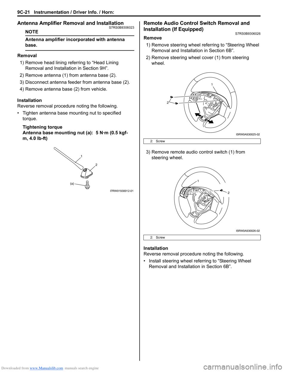
Antenna Amplifier Removal and InstallationS7RS0B9306023
NOTE
Antenna amplifier incorporated with antenna
base.
Removal1) Remove head lining referring to “Head Lining Removal and Installa tion in Section 9H”.
2) Remove antenna (1) from antenna base (2).
3) Disconnect antenna feeder from antenna base (2).
4) Remove antenna base (2) from vehicle.
Installation
Reverse removal procedure noting the following.
• Tighten antenna base mounting nut to specified torque.
Tightening torque
Antenna base mounting nut (a): 5 N·m (0.5 kgf-
m, 4.0 lb-ft)
Remote Audio Control Switch Removal and
Installation (If Equipped)
S7RS0B9306026
Remove
1) Remove steering wheel re ferring to “Steering Wheel
Removal and Installati on in Section 6B”.
2) Remove steering wheel cover (1) from steering wheel.
3) Remove remote audio control switch (1) from steering wheel.
Installation
Reverse removal procedure noting the following.
• Install steering wheel referring to “Steering Wheel Removal and Installati on in Section 6B”.
(a)1
2
I7RW01930012-01
2: Screw
2: Screw
2
1
I5RW0A930025-02
1
2
I5RW0A930026-02
Page 1331 of 1496
Downloaded from www.Manualslib.com manuals search engine Glass / Windows / Mirrors: 9E-4
Repair Instructions
Windshield Removal and InstallationS7RS0B9506001
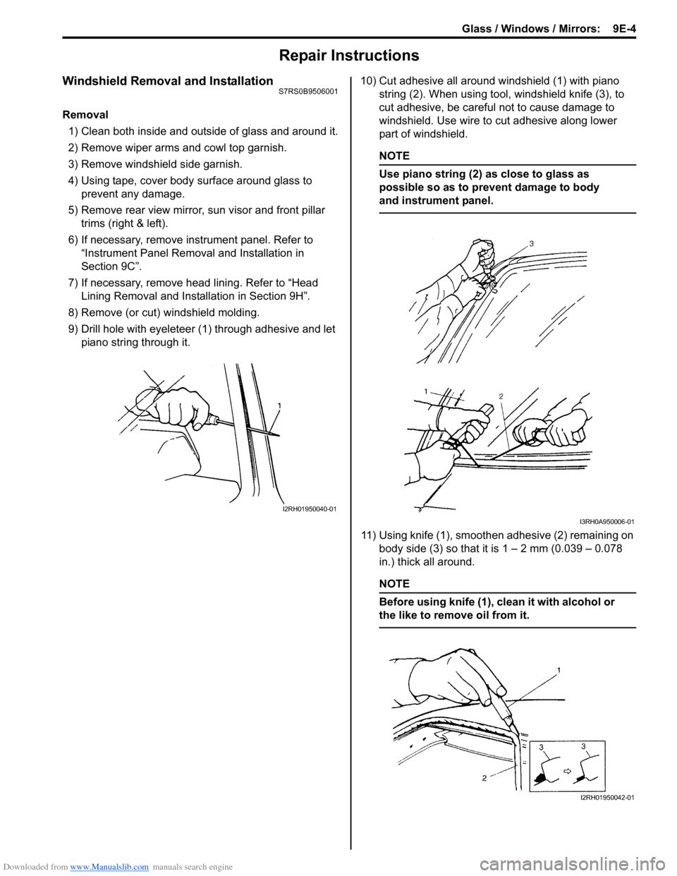
Removal1) Clean both inside and outside of glass and around it.
2) Remove wiper arms and cowl top garnish.
3) Remove windshield side garnish.
4) Using tape, cover body surface around glass to prevent any damage.
5) Remove rear view mirror , sun visor and front pillar
trims (right & left).
6) If necessary, remove instrument panel. Refer to “Instrument Panel Removal and Installation in
Section 9C”.
7) If necessary, remove he ad lining. Refer to “Head
Lining Removal and Installation in Section 9H”.
8) Remove (or cut) windshield molding.
9) Drill hole with eyeleteer (1 ) through adhesive and let
piano string through it. 10) Cut adhesive all around windshield (1) with piano
string (2). When using tool, windshield knife (3), to
cut adhesive, be careful not to cause damage to
windshield. Use wire to cut adhesive along lower
part of windshield.
NOTE
Use piano string (2) as close to glass as
possible so as to prevent damage to body
and instrument panel.
11) Using knife (1), smoothen adhesive (2) remaining on body side (3) so that it is 1 – 2 mm (0.039 – 0.078
in.) thick all around.
NOTE
Before using knife (1), clean it with alcohol or
the like to remove oil from it.
I2RH01950040-01
I3RH0A950006-01
I2RH01950042-01