2008 SUZUKI SWIFT Indicator fuse
[x] Cancel search: Indicator fusePage 1167 of 1496

Downloaded from www.Manualslib.com manuals search engine Table of Contents 9- i
9
Section 9
CONTENTS
Body, Cab and Accessories
Precautions ................................................. 9-1
Precautions............................................................. 9-1
Precautions on Body, Cab and Accessories ......... 9-1
Precautions for Body Service ................................ 9-1
Fastener Caution for Body Service ....................... 9-1
Wiring Systems............... ......................... 9A-1
Precautions........................................................... 9A-1
Cautions in Body Electrical System Servicing..... 9A-1
General Description ............................................. 9A-1 Abbreviations ...................................................... 9A-1
Wire / Connector Color Sy mbols ......................... 9A-1
Symbols and Marks ............................................ 9A-2
How to Read Connector Layout Diagram ........... 9A-4
How to Read Connector Codes and Terminal Nos.................................................................... 9A-5
How to Read Ground Point ................................. 9A-7
How to Read Power Supply Diagram.................. 9A-8
How to Read System Circuit Diagram................. 9A-8
Connector Layout Diagram . .............................. 9A-10
Connector Layout Diagram ............................... 9A-10
Engine Compartment .......... .............................. 9A-10
Instrument Panel ............................................... 9A-16
Door, Roof......................................................... 9A-20
Floor .................................................................. 9A-23
Rear .................................................................. 9A-29
Ground Point ...................................................... 9A-30 Ground (earth) Point ......................................... 9A-30
Power Supply Diagram ........ .............................. 9A-31
Power Supply Diagram ....... .............................. 9A-31
Fuses and the Protected Parts ......................... 9A-33
Fuses in Main Fuse Box (RHD) ........................ 9A-33
Fuses in Main Fuse Box (LHD) ......................... 9A-33
Individual Circuit Fuse Box No. 1 ...................... 9A-34
Individual Circuit Fuse Box No. 2 (In J/B) ......... 9A-35
Junction Block (J/B) Connector / Fuse Layout .. 9A-37
Junction Block Inner Circuit (Overview) ............ 9A-38
Junction Block Inner Circuit (Detail) .................. 9A-40
System Circuit Diagram... .................................. 9A-45
System Circuit Diagram .. .................................. 9A-45
A-1 Cranking System Circ uit Diagram .............. 9A-46
A-2 Charging System Circu it Diagram .............. 9A-47
A-3 Ignition System Circu it Diagram ................. 9A-48
A-4 Cooling System Circuit Diagram................. 9A-49 A-5 Engine and A/C Control System Circuit
Diagram........................................................... 9A-50
A-6 A/T Control System Circuit Diagram........... 9A-55
A-7 Immobilizer System Circuit Diagram .......... 9A-57
A-8 Body Control System Circuit Diagram ........ 9A-58
B-1 Windshield Wiper and Washer Circuit Diagram........................................................... 9A-62
B-2 Rear Wiper and Washer Circuit Diagram ... 9A-63
B-3 Rear Defogger Circuit Diagram .................. 9A-64
B-4 Power Window Circuit Diagram .................. 9A-65
B-5 Power Door Lock Circu it Diagram .............. 9A-67
B-6 Power Mirror Circuit Diagram ..................... 9A-69
B-7 Horn Circuit Diagram .................................. 9A-70
B-8 Seat Heater Circuit Diagram....................... 9A-71
B-9 Keyless Start System Circuit Diagram........ 9A-72
C-1 Combination Mete r Circuit Diagram
(Meter)............................................................. 9A-73
C-2 Combination Mete r Circuit Diagram
(Indicator) ........................................................ 9A-74
C-3 Combination Mete r Circuit Diagram
(Warning Light)................................................ 9A-75
D-1 Headlight System Circuit Diagram ............. 9A-77
D-2 Position, Tail and Licence Plate Light System Circuit Diagram .................................. 9A-79
D-3 Front Fog Light System Circuit Diagram .... 9A-80
D-4 Illumination Light System Circuit Diagram .. 9A-81
D-5 Interior Light System Circuit Diagram......... 9A-82
D-6 Turn Signal and Hazard Warning Light System Circuit Diagram .................................. 9A-83
D-7 Brake Light System Circuit Diagram .......... 9A-85
D-8 Back-Up Light System Circuit Diagram ...... 9A-86
D-9 Headlight Beam Leveling System Circuit Diagram........................................................... 9A-87
D-10 Rear Fog Light Circuit Diagram ................ 9A-88
E-1 Heater System Circuit Diagram .................. 9A-89
E-2 Auto A/C System Circuit Diagram .............. 9A-91
F-1 Air-Bag System Circuit Diagram ................. 9A-93
F-2 Anti-Lock Brake System Circuit Diagram.... 9A-95
F-3 Electronic Stab ility Program System
Circuit Diagram .................. ............................. 9A-97
F-4 Power Steering System Circuit Diagram .... 9A-99
G-1 Audio System Circuit Diagram ................. 9A-101
G-2 Multi Information Display / Accessory Socket System Circuit Diagram .................... 9A-102
List of Connector .............................................9A-103
Page 1299 of 1496
Downloaded from www.Manualslib.com manuals search engine Instrumentation / Driver Info. / Horn: 9C-4
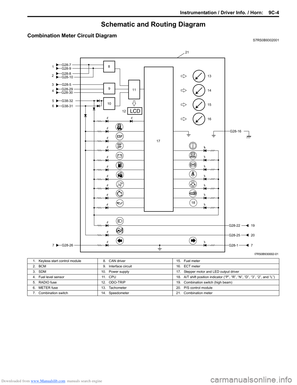
Schematic and Routing Diagram
Combination Meter Circuit DiagramS7RS0B9302001
16
15
14
13
G28-5
5
6
3
G28-26
7
G28-2219
G28-2520
G28-17
12
10 11
21
9
17
G28-304G28-29
18
G28-16
G28-9
G28-10G28-8 G28-7
1
2 8
G38-31
G38-32
I7RS0B930002-01
1. Keyless start control module
8. CAN driver 15. Fuel meter
2. BCM 9. Interface circuit 16. ECT meter
3. SDM 10. Power supply 17. Stepper motor and LED output driver
4. Fuel level sensor 11. CPU 18. A/T shift position indicator (“P”, “R”, “N”, “D”, “3”, “2”, and “L”)
5. RADIO fuse 12. ODO-TRIP 19. Combination switch (high beam)
6. METER fuse 13. Tachometer 20. P/S control module
7. Combination switch 14. Speedometer 21. Combination meter
Page 1304 of 1496
Downloaded from www.Manualslib.com manuals search engine 9C-9 Instrumentation / Driver Info. / Horn:
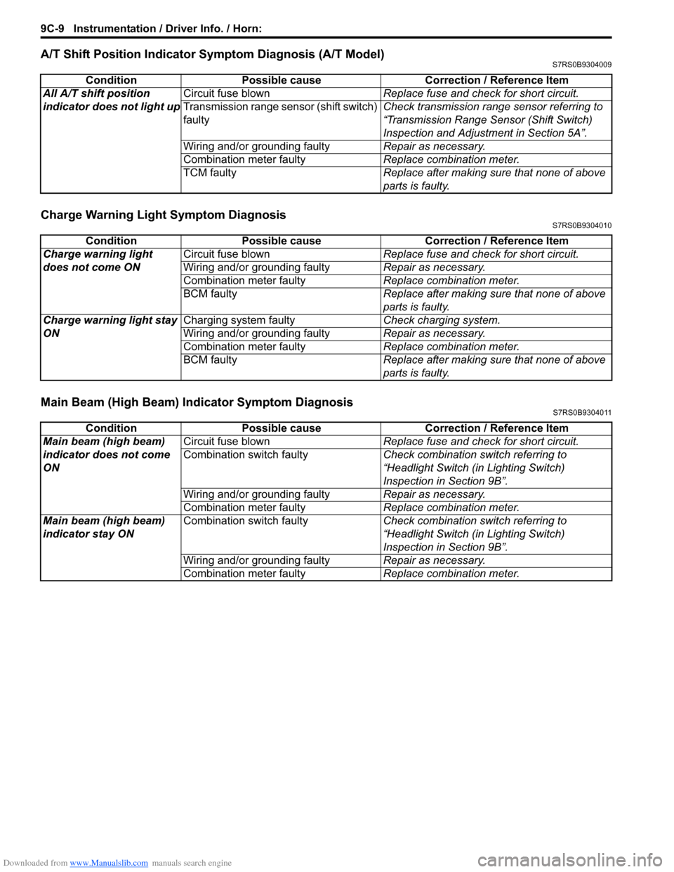
A/T Shift Position Indicator Symptom Diagnosis (A/T Model)S7RS0B9304009
Charge Warning Light Symptom DiagnosisS7RS0B9304010
Main Beam (High Beam) Indicator Symptom DiagnosisS7RS0B9304011
ConditionPossible cause Correction / Reference Item
All A/T shift position
indicator does not light up Circuit fuse blown
Replace fuse and check for short circuit.
Transmission range sens or (shift switch)
faulty Check transmission range sensor referring to
“Transmission Range Sensor (Shift Switch)
Inspection and Adjustment in Section 5A”.
Wiring and/or grounding faulty Repair as necessary.
Combination meter faulty Replace combination meter.
TCM faulty Replace after making sure that none of above
parts is faulty.
ConditionPossible cause Correction / Reference Item
Charge warning light
does not come ON Circuit fuse blown
Replace fuse and check for short circuit.
Wiring and/or grounding faulty Repair as necessary.
Combination meter faulty Replace combination meter.
BCM faulty Replace after making sure that none of above
parts is faulty.
Charge warning light stay
ON Charging system faulty
Check charging system.
Wiring and/or grounding faulty Repair as necessary.
Combination meter faulty Replace combination meter.
BCM faulty Replace after making sure that none of above
parts is faulty.
ConditionPossible cause Correction / Reference Item
Main beam (high beam)
indicator does not come
ON Circuit fuse blown
Replace fuse and check for short circuit.
Combination switch faulty Check combination switch referring to
“Headlight Switch (in Lighting Switch)
Inspection in Section 9B”.
Wiring and/or grounding faulty Repair as necessary.
Combination meter faulty Replace combination meter.
Main beam (high beam)
indicator stay ON Combination switch faulty
Check combination switch referring to
“Headlight Switch (in Lighting Switch)
Inspection in Section 9B”.
Wiring and/or grounding faulty Repair as necessary.
Combination meter faulty Replace combination meter.
Page 1447 of 1496
Downloaded from www.Manualslib.com manuals search engine Immobilizer Control System: 10C-4
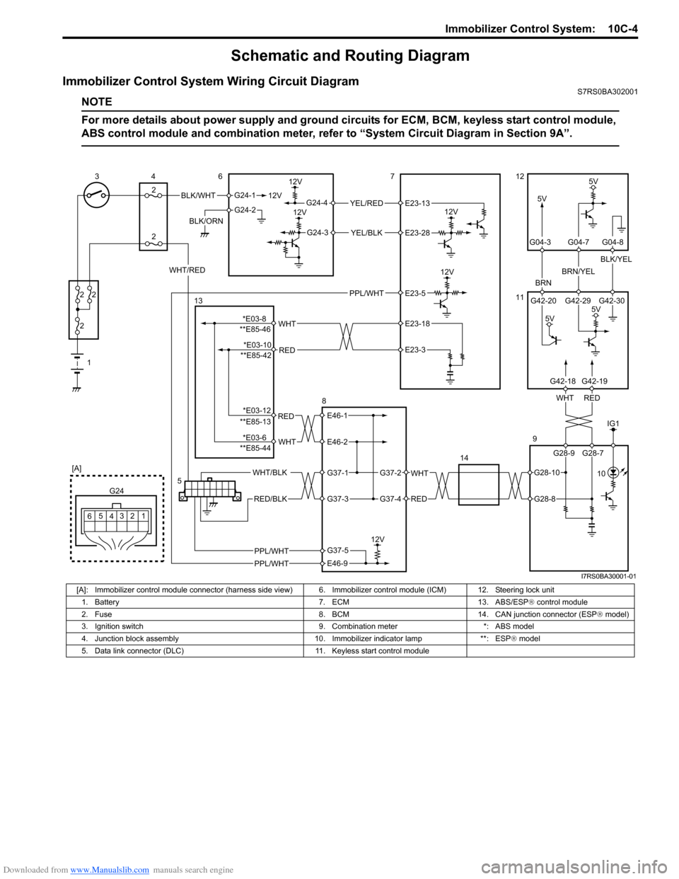
Schematic and Routing Diagram
Immobilizer Control System Wiring Circuit DiagramS7RS0BA302001
NOTE
For more details about power supply and ground circuits for ECM, BCM, keyless start control module,
ABS control module and combination meter, refer to “System Ci rcuit Diagram in Section 9A”.
BLK/WHT
BLK/ORN12V
G24-1
G24-2
12V
5V
12V
12VYEL/RED
YEL/BLK
G24-4
G24-3
12V
5V
BRN
BRN/YEL
BLK/YEL
1
2
2 2
2
34
2 6712
11
9
14
12
3
4
G24
[A]
5
6
REDWHT
G42-20 G42-29 G42-30
G04-3 G04-7 G04-8
WHT/RED
5V
5V
5
G28-9 G28-7
G42-18G42-19
E23-13
E23-28
IG1
PPL/WHT 10
PPL/WHT
PPL/WHT
E23-5
RED
WHT**E85-46E23-18
E23-3
RED
WHT
E46-1
E46-2
WHT
RED
G37-2
G37-4
WHT/BLK
RED/BLK
G37-1
G37-3
12V
E46-9
G37-5
13
8
**E85-42
**E85-13
**E85-44
G28-10
G28-8
*E03-8 *E03-10
*E03-12
*E03-6
I7RS0BA30001-01
[A]: Immobilizer control module connector (harness side vi ew) 6. Immobilizer control module (ICM) 12. Steering lock unit
1. Battery 7. ECM 13. ABS/ESP ® control module
2. Fuse 8. BCM 14. CAN junction connector (ESP ® model)
3. Ignition switch 9. Combination meter *: ABS model
4. Junction block assembly 10. Immobilizer indicator lamp **: ESP ® model
5. Data link connector (DLC) 11. Keyless start control module
Page 1451 of 1496
Downloaded from www.Manualslib.com manuals search engine Immobilizer Control System: 10C-8
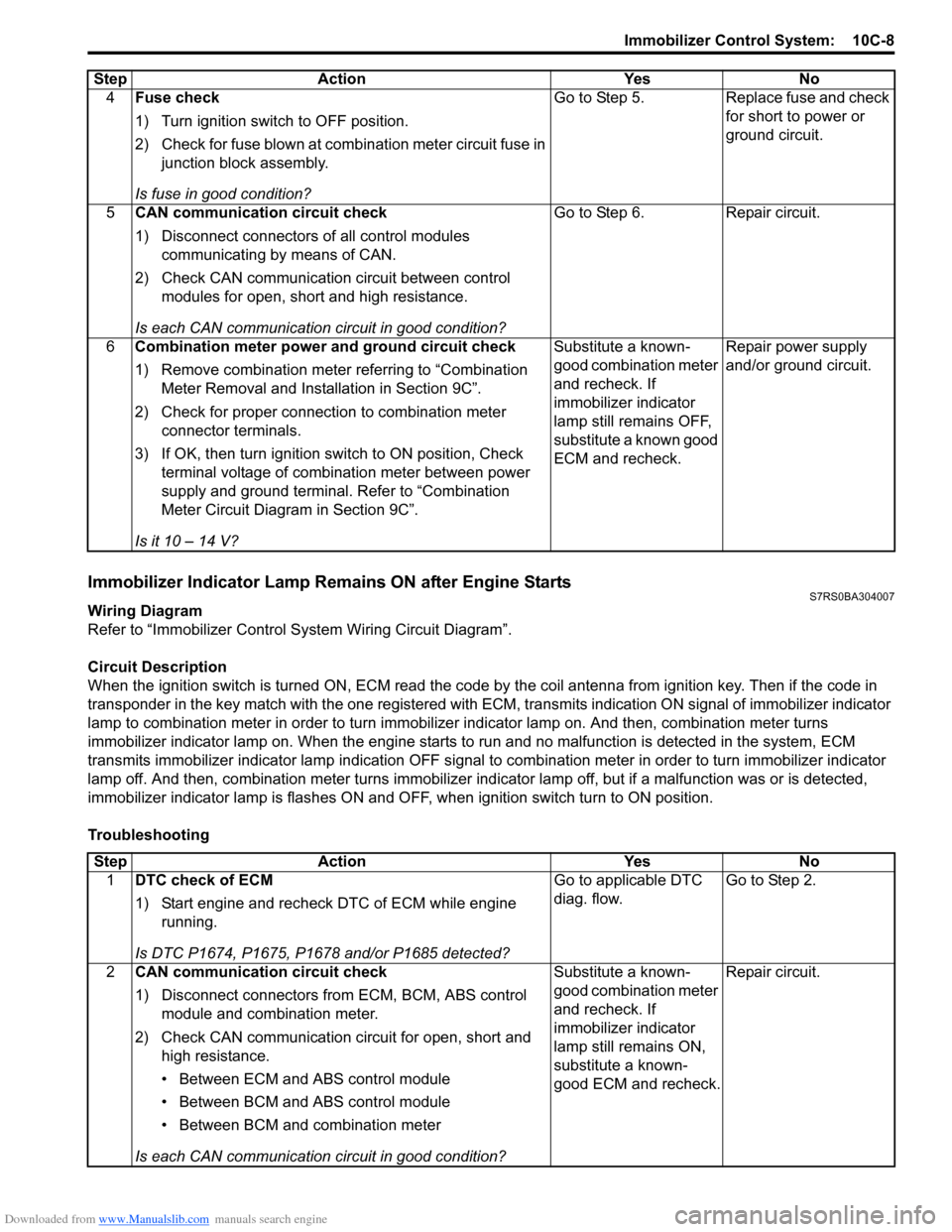
Immobilizer Indicator Lamp Remains ON after Engine StartsS7RS0BA304007
Wiring Diagram
Refer to “Immobilizer Control S ystem Wiring Circuit Diagram”.
Circuit Description
When the ignition switch is turned ON, ECM read the code by the coil antenna from ignition key. Then if the code in
transponder in the key match with the one registered with ECM, transmits indication ON signal of immobilizer indicator
lamp to combination meter in order to turn immobilizer indicator lamp on. And then, combination meter turns
immobilizer indicator lamp on. When th e engine starts to run and no malfunction is detected in the system, ECM
transmits immobilizer indicator lamp indication O FF signal to combination meter in order to turn immobilizer indicator
lamp off. And then, comb ination meter turns immobilizer indicator lamp off, but if a malfunction was or is detected,
immobilizer indicator lamp is flashes ON and OF F, when ignition switch turn to ON position.
Troubleshooting 4
Fuse check
1) Turn ignition switch to OFF position.
2) Check for fuse blown at combination meter circuit fuse in
junction block assembly.
Is fuse in good condition? Go to Step 5. Replace fuse and check
for short to power or
ground circuit.
5 CAN communication circuit check
1) Disconnect connectors of all control modules
communicating by means of CAN.
2) Check CAN communication circuit between control modules for open, short and high resistance.
Is each CAN communication circuit in good condition? Go to Step 6. Repair circuit.
6 Combination meter power and ground circuit check
1) Remove combination meter referring to “Combination
Meter Removal and Installation in Section 9C”.
2) Check for proper connection to combination meter connector terminals.
3) If OK, then turn ignition switch to ON position, Check terminal voltage of combination meter between power
supply and ground terminal. Refer to “Combination
Meter Circuit Diagram in Section 9C”.
Is it 10 – 14 V? Substitute a known-
good combination meter
and recheck. If
immobilizer indicator
lamp still remains OFF,
substitute a known good
ECM and recheck.
Repair power supply
and/or ground circuit.
Step Action Yes No
Step
Action YesNo
1 DTC check of ECM
1) Start engine and recheck DTC of ECM while engine
running.
Is DTC P1674, P1675, P1678 and/or P1685 detected? Go to applicable DTC
diag. flow.
Go to Step 2.
2 CAN communication circuit check
1) Disconnect connectors from ECM, BCM, ABS control
module and combination meter.
2) Check CAN communication circuit for open, short and high resistance.
• Between ECM and ABS control module
• Between BCM and ABS control module
• Between BCM and combination meter
Is each CAN communication circuit in good condition? Substitute a known-
good combination meter
and recheck. If
immobilizer indicator
lamp still remains ON,
substitute a known-
good ECM and recheck.
Repair circuit.
Page 1474 of 1496
Downloaded from www.Manualslib.com manuals search engine 10E-12 Keyless Start System:
DTC ClearanceS7RS0BA504009
1) Perform Steps 1) through 5) of DTC check procedure and have DTC indicated.
2) Open driver side door.
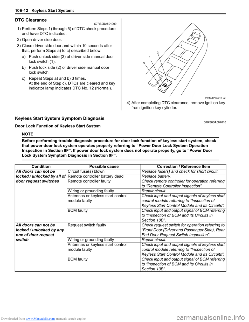
3) Close driver side door and within 10 seconds after that, perform Steps a) to c) described below.
a) Push unlock side (3) of driver side manual door lock switch (1).
b) Push lock side (2) of driver side manual door lock switch.
c) Repeat Steps a) and b) 3 times. At the end of Step c), DTCs are cleared and key
indicator lamp indicates DTC No. 12 (Normal).
4) After completing DTC clearance, remove ignition key from ignition key cylinder.
Keyless Start System Symptom DiagnosisS7RS0BA504010
Door Lock Function of Keyless Start System
NOTE
Before performing trouble diagnosis procedure for door lock function of keyless start system, check
that power door lock system operates properly referring to “Power Door Lock System Operation
Inspection in Section 9F”. If power door lock system does not operate properly, go to “Power Door
Lock System Symptom Diagnosis in Section 9F”.
1
3 2
I4RS0BA50011-02
Condition
Possible cause Correction / Reference Item
All doors can not be
locked / unlocked by all of
door request switches Circuit fuse(s) blown
Replace fuse(s) and check for short circuit.
Remote controller battery dead Replace battery.
Remote controller faulty Check remote controller for operation referring
to “Remote Controller Inspection”.
Wiring or grounding faulty Repair circuit.
Antennas or keyless start control
module faulty Check input and output signals of keyless start
control module referring to “Inspection of
Keyless Start Control Mo
dule and Its Circuits”.
BCM faulty Check input and output signal of BCM referring
to “Inspection of BCM and its Circuits in
Section 10B”.
All doors can not be
locked / unlocked by any
one of door request
switch Request switch faulty
Check request switch for operation referring to
“Front Door (Driver and Passenger Side), Rear
End Door Request Switch Inspection”.
Wiring or grounding faulty Repair circuit.
Antennas or keyless start control
module faulty Check input and output signals of keyless start
control module referring to “Inspection of
Keyless Start Control Mo
dule and Its Circuits”.
BCM faulty Check input and output signal of BCM referring
to “Inspection of BCM and its Circuits in
Section 10B”.
Page 1475 of 1496
Downloaded from www.Manualslib.com manuals search engine Keyless Start System: 10E-13
Keyless Engine Start Function
NOTE
Before performing symptom diagnosis procedure for keyless engine start system, check that engine
starts by using ignition key. If it cannot be started by using ignition key, go to “Engine Symptom
Diagnosis in Section 1A”.
Keyless Start System Operation InspectionS7RS0BA504011
Keyless engine start operation
1) Sit in driver seat with re mote controller carried with
you.
2) Check that all doors are closed and ignition key is not inserted in ignition key cylinder.
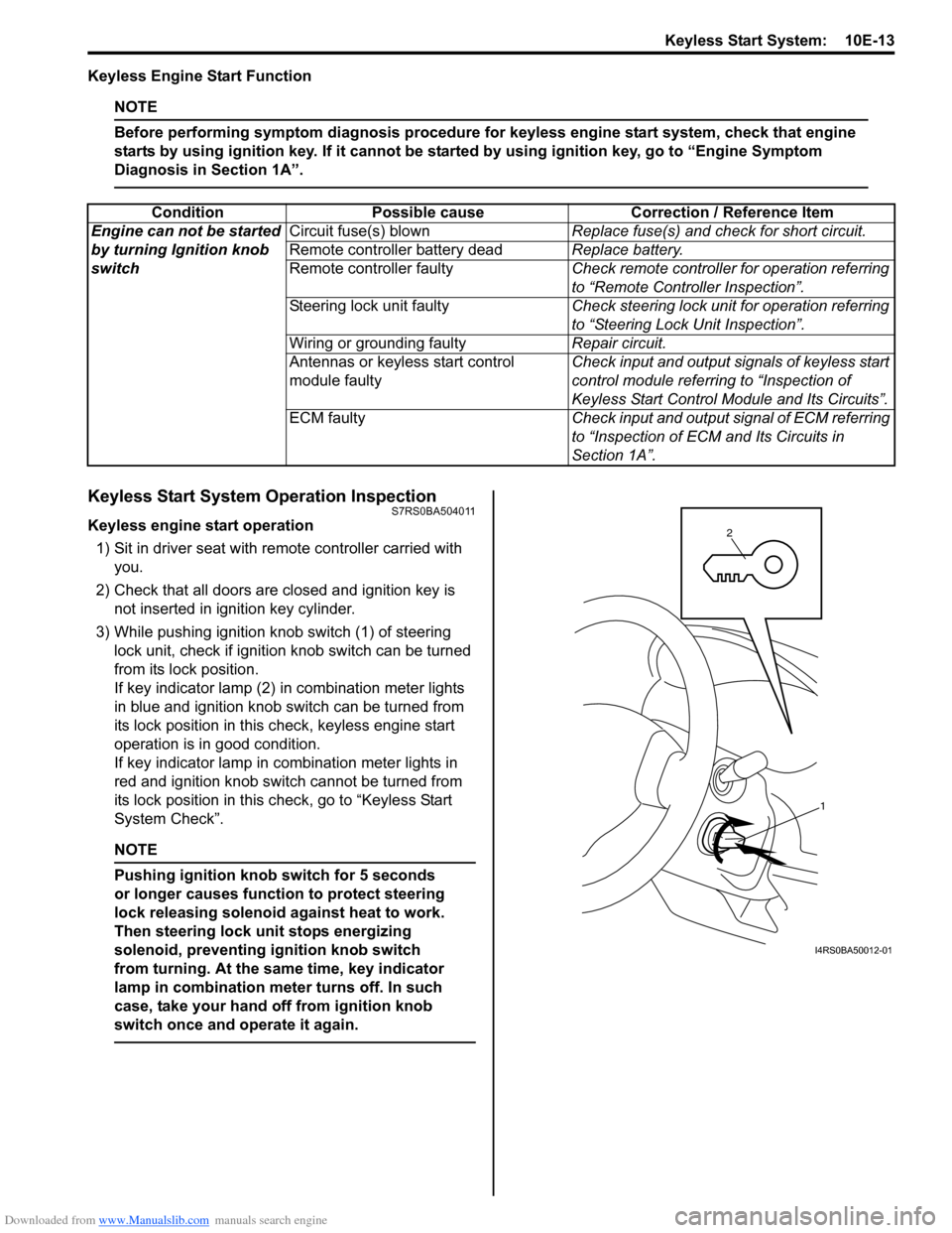
3) While pushing ignition knob switch (1) of steering lock unit, check if ignition knob switch can be turned
from its lock position.
If key indicator lamp (2) in combination meter lights
in blue and ignition knob switch can be turned from
its lock position in this check, keyless engine start
operation is in good condition.
If key indicator lamp in combination meter lights in
red and ignition knob switch cannot be turned from
its lock position in this check, go to “Keyless Start
System Check”.
NOTE
Pushing ignition knob switch for 5 seconds
or longer causes function to protect steering
lock releasing solenoid against heat to work.
Then steering lock unit stops energizing
solenoid, preventing ignition knob switch
from turning. At the same time, key indicator
lamp in combination mete r turns off. In such
case, take your hand off from ignition knob
switch once and operate it again.
Condition Possible cause Correction / Reference Item
Engine can not be started
by turning Ignition knob
switch Circuit fuse(s) blown
Replace fuse(s) and check for short circuit.
Remote controller battery dead Replace battery.
Remote controller faulty Check remote controller for operation referring
to “Remote Controller Inspection”.
Steering lock unit faulty Check steering lock unit for operation referring
to “Steering Lock Unit Inspection”.
Wiring or grounding faulty Repair circuit.
Antennas or keyless start control
module faulty Check input and output signals of keyless start
control module referring to “Inspection of
Keyless Start Control Mo
dule and Its Circuits”.
ECM faulty Check input and output signal of ECM referring
to “Inspection of ECM and Its Circuits in
Section 1A”.
1
2
I4RS0BA50012-01
Page 1481 of 1496
Downloaded from www.Manualslib.com manuals search engine Keyless Start System: 10E-19
TroubleshootingStep Action Yes No 1 Combination meter power and ground circuit check
1) Turn ignition switch to ON position.
Do warning lights in combi nation meter other than key
indicator lamp light up? Go to Step 2. Check main fuse, circuit
fuse, combination meter
power and ground
circuit.
2 Driver side door request switch and its circuit check
1) Check driver side door request switch and its circuit
referring to “DTC No. 51 / No . 52 / No. 53: Driver Side /
Passenger Side / Rear End Door Request Switch
Failure”.
Is it in good condition? Go to Step 3. Repair or replace
malfunction part.
3 Key reminder switch and its circuit check
1) Turn ignition switch to OFF position.
2) Disconnect connector from ignition switch.
3) Check key reminder switch for operation referring to
“Ignition Switch Inspection in Section 9C”.
4) If OK, check for open, short and high resistance in key reminder switch circuit.
Is it in good condition? Go to Step 4. Repair or replace
malfunction part.
4 Keyless start control module power and ground circuit
check
1) Check keyless start control module power and ground
circuit for condition referrin g to “Keyless Start Control
Module Power and Ground Circuit Check”.
Is it in good condition? Go to Step 5. Repair circuit.
5 CAN communication circuit check
1) Turn ignition switch to OFF position.
2) Disconnect connectors of all control modules
communicating by means of CAN.
3) Check CAN communication circuit between control modules for open, short and high resistance.
Is each CAN communication circuit in good condition? Substitute a known-
good keyless start
control module and
recheck.
Repair circuit.