2008 SUZUKI SWIFT Clock
[x] Cancel search: ClockPage 410 of 1496
Downloaded from www.Manualslib.com manuals search engine 1I-9 Starting System:
Specifications
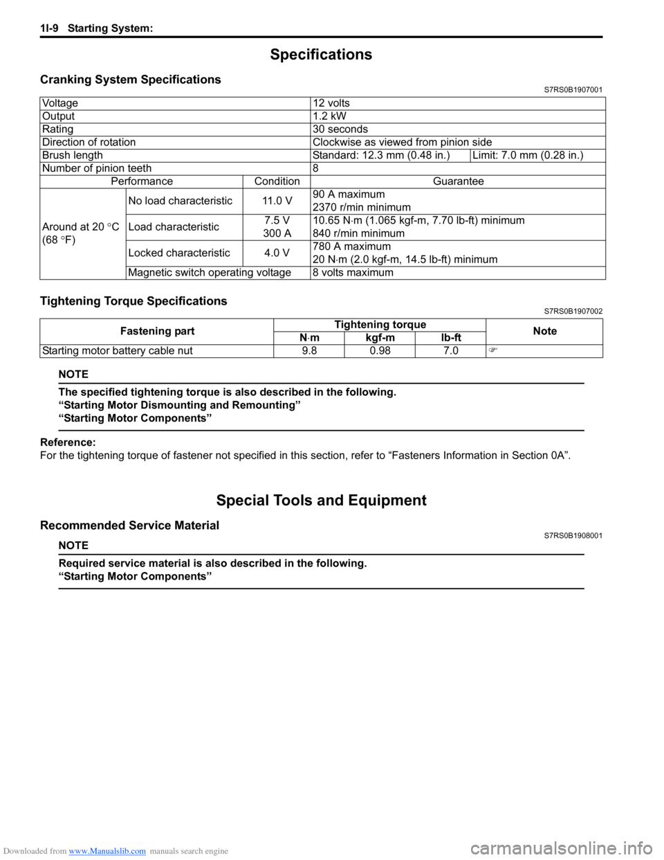
Cranking System SpecificationsS7RS0B1907001
Tightening Torque SpecificationsS7RS0B1907002
NOTE
The specified tightening torque is also described in the following.
“Starting Motor Dismounting and Remounting”
“Starting Motor Components”
Reference:
For the tightening torque of fastener not specified in this section, refer to “Fasteners Information in Section 0A”.
Special Tools and Equipment
Recommended Service MaterialS7RS0B1908001
NOTE
Required service material is also described in the following.
“Starting Motor Components”
Voltage 12 volts
Output 1.2 kW
Rating 30 seconds
Direction of rotation Clockwise as viewed from pinion side
Brush length Standard: 12.3 mm (0.48 in.) Limit: 7.0 mm (0.28 in.)
Number of pinion teeth 8
Performance Condition Guarantee
Around at 20 °C
(68 °F) No load characteristic 11.0 V
90 A maximum
2370 r/min minimum
Load characteristic 7.5 V
300 A 10.65 N
⋅m (1.065 kgf-m, 7.70 lb-ft) minimum
840 r/min minimum
Locked characteristic 4.0 V 780 A maximum
20 N
⋅m (2.0 kgf-m, 14.5 lb-ft) minimum
Magnetic switch operating voltage 8 volts maximum
Fastening part Tightening torque
Note
N ⋅mkgf-mlb-ft
Starting motor battery cable nut 9.8 0.98 7.0 �)
Page 418 of 1496
Downloaded from www.Manualslib.com manuals search engine 1J-8 Charging System:
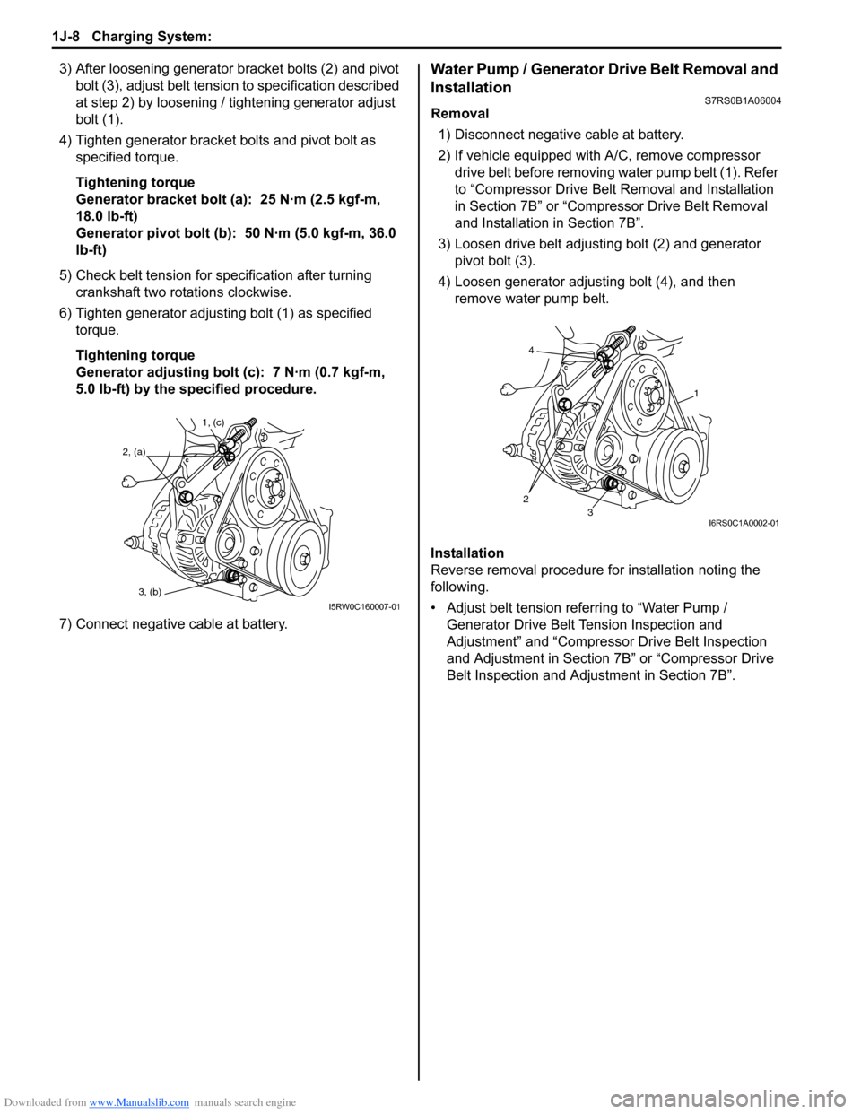
3) After loosening generator bracket bolts (2) and pivot bolt (3), adjust belt tensio n to specification described
at step 2) by loosening / tightening generator adjust
bolt (1).
4) Tighten generator bracket bolts and pivot bolt as specified torque.
Tightening torque
Generator bracket bolt (a): 25 N·m (2.5 kgf-m,
18.0 lb-ft)
Generator pivot bolt (b): 50 N·m (5.0 kgf-m, 36.0
lb-ft)
5) Check belt tension for specification after turning crankshaft two rotations clockwise.
6) Tighten generator adjusting bolt (1) as specified torque.
Tightening torque
Generator adjusting bolt (c): 7 N·m (0.7 kgf-m,
5.0 lb-ft) by the specified procedure.
7) Connect negative cable at battery.Water Pump / Generator Drive Belt Removal and
Installation
S7RS0B1A06004
Removal 1) Disconnect negative cable at battery.
2) If vehicle equipped with A/C, remove compressor drive belt before removing water pump belt (1). Refer
to “Compressor Drive Belt Removal and Installation
in Section 7B” or “Compr essor Drive Belt Removal
and Installation in Section 7B”.
3) Loosen drive belt adjusting bolt (2) and generator pivot bolt (3).
4) Loosen generator adjusting bolt (4), and then remove water pump belt.
Installation
Reverse removal procedure for installation noting the
following.
• Adjust belt tension referring to “Water Pump / Generator Drive Belt Tension Inspection and
Adjustment” and “Compressor Drive Belt Inspection
and Adjustment in Section 7B” or “Compressor Drive
Belt Inspection and Adjustment in Section 7B”.
1, (c)
2, (a)
3, (b)
I5RW0C160007-01
4
23
1
I6RS0C1A0002-01
Page 423 of 1496
Downloaded from www.Manualslib.com manuals search engine Charging System: 1J-13
Specifications
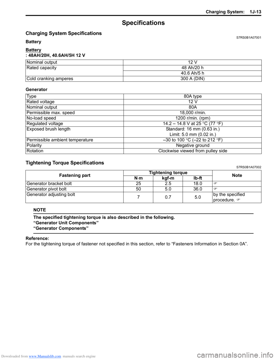
Charging System SpecificationsS7RS0B1A07001
Battery
Battery
: 48AH/20H, 40.6AH/5H 12 V
Generator
Tightening Torque SpecificationsS7RS0B1A07002
NOTE
The specified tightening torque is also described in the following.
“Generator Unit Components”
“Generator Components”
Reference:
For the tightening torque of fastener not specified in this section, refer to “Fasteners Information in Section 0A”.
Nominal output
12 V
Rated capacity 48 Ah/20 h
40.6 Ah/5 h
Cold cranking amperes 300 A (DIN)
Ty p e 80A type
Rated voltage 12 V
Nominal output 80A
Permissible max. speed 18,000 r/min.
No-load speed 1200 r/min. (rpm)
Regulated voltage 14.2 – 14.8 V at 25 ° C (77 °F)
Exposed brush length Standard: 16 mm (0.63 in.)
Limit: 5.0 mm (0.02 in.)
Permissible ambient temperature –30 to 100 °C (–22 to 212 °F)
Polarity Negative ground
Rotation Clockwise viewed from pulley side
Fastening partTightening torque
Note
N ⋅mkgf-mlb-ft
Generator bracket bolt 25 2.5 18.0 �)
Generator pivot bolt 50 5.0 36.0 �)
Generator adjusting bolt 70.7 5.0by the specified
procedure.
�)
Page 506 of 1496
Downloaded from www.Manualslib.com manuals search engine 4A-8 Brake Control System and Diagnosis:
Excessive Pedal Travel InspectionS7RS0B4106003
1) Start engine.
2) Depress brake pedal a few times.
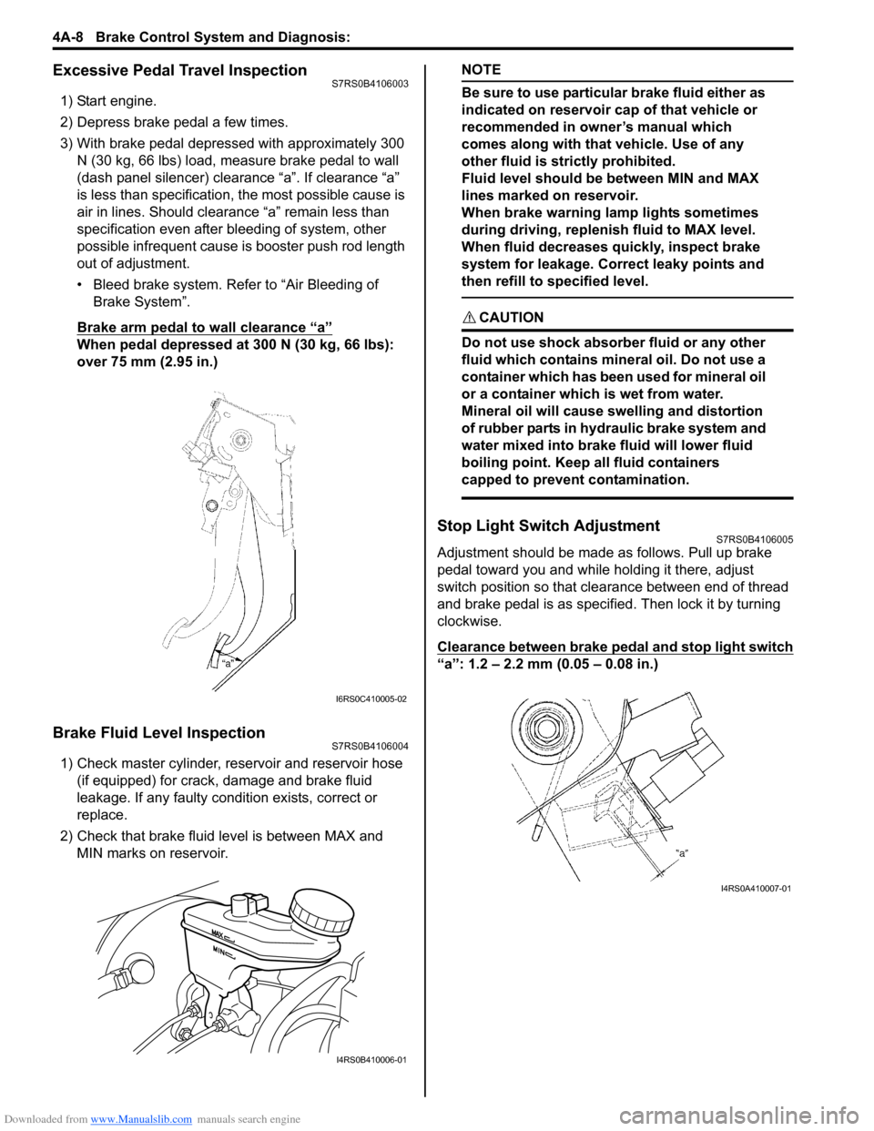
3) With brake pedal depressed with approximately 300 N (30 kg, 66 lbs) load, measure brake pedal to wall
(dash panel silencer) clearance “a”. If clearance “a”
is less than specification, the most possible cause is
air in lines. Should clearance “a” remain less than
specification even after bleeding of system, other
possible infrequent cause is booster push rod length
out of adjustment.
• Bleed brake system. Refer to “Air Bleeding of Brake System”.
Brake arm pedal to wall clearance “a”
When pedal depressed at 300 N (30 kg, 66 lbs):
over 75 mm (2.95 in.)
Brake Fluid Level InspectionS7RS0B4106004
1) Check master cylinder, reservoir and reservoir hose (if equipped) for crack, damage and brake fluid
leakage. If any faulty condition exists, correct or
replace.
2) Check that brake fluid level is between MAX and MIN marks on reservoir.
NOTE
Be sure to use particular brake fluid either as
indicated on reservoir cap of that vehicle or
recommended in owner’s manual which
comes along with that vehicle. Use of any
other fluid is strictly prohibited.
Fluid level should be between MIN and MAX
lines marked on reservoir.
When brake warning lamp lights sometimes
during driving, replenis h fluid to MAX level.
When fluid decreases quickly, inspect brake
system for leakage. Correct leaky points and
then refill to specified level.
CAUTION!
Do not use shock absorber fluid or any other
fluid which contains mineral oil. Do not use a
container which has been used for mineral oil
or a container which is wet from water.
Mineral oil will cause swelling and distortion
of rubber parts in hydraulic brake system and
water mixed into brake fluid will lower fluid
boiling point. Keep all fluid containers
capped to prevent contamination.
Stop Light Switch AdjustmentS7RS0B4106005
Adjustment should be made as follows. Pull up brake
pedal toward you and while holding it there, adjust
switch position so that clea rance between end of thread
and brake pedal is as specified. Then lock it by turning
clockwise.
Clearance between brake pedal and stop light switch
“a”: 1.2 – 2.2 mm (0.05 – 0.08 in.)
I6RS0C410005-02
I4RS0B410006-01
I4RS0A410007-01
Page 526 of 1496
Downloaded from www.Manualslib.com manuals search engine 4C-2 Rear Brakes:
Rear Disc Brake Pad Removal and InstallationS7RS0B4306002
NOTE
When replacing brake pad, replace it on the
right and left.
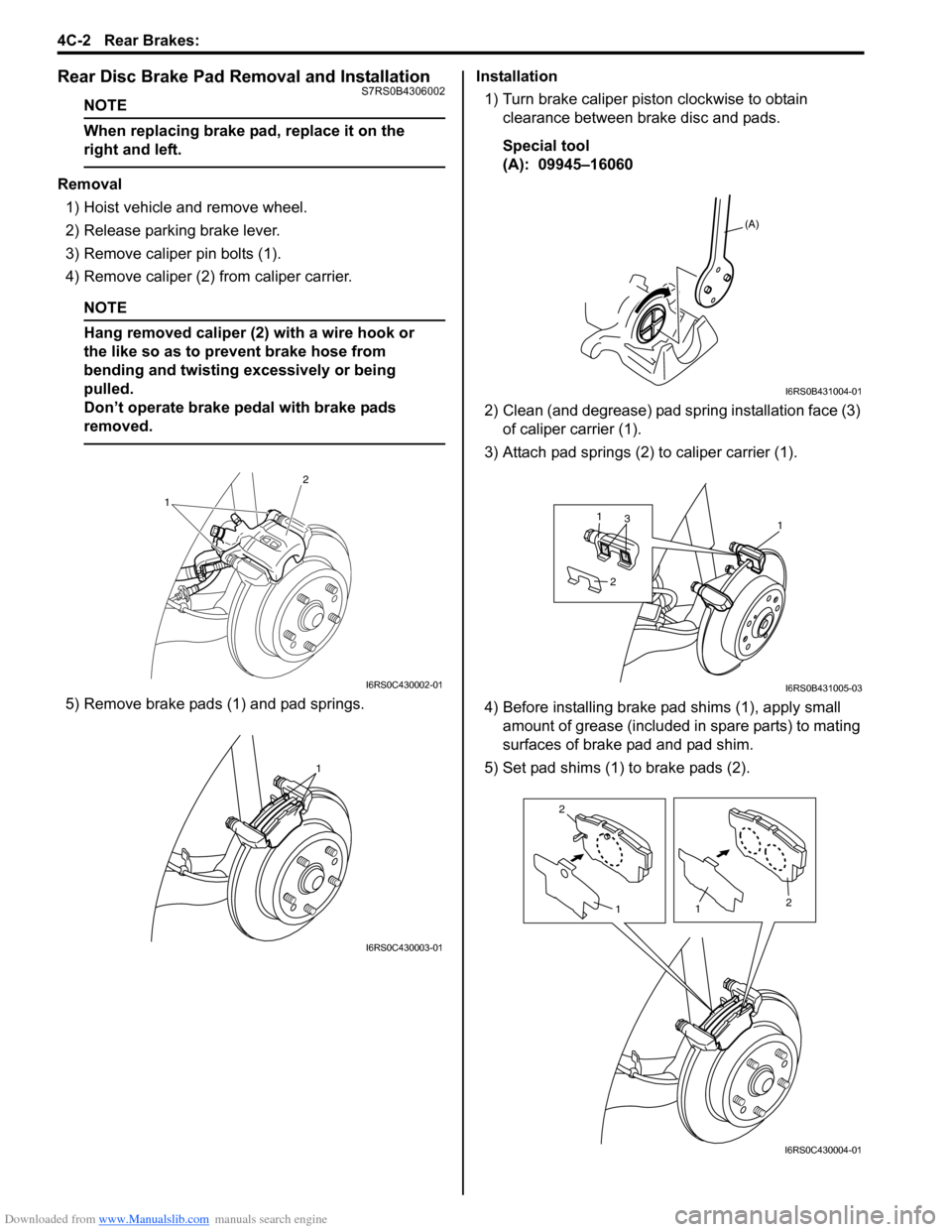
Removal1) Hoist vehicle and remove wheel.
2) Release parking brake lever.
3) Remove caliper pin bolts (1).
4) Remove caliper (2) from caliper carrier.
NOTE
Hang removed caliper (2) with a wire hook or
the like so as to prevent brake hose from
bending and twisting excessively or being
pulled.
Don’t operate brake pedal with brake pads
removed.
5) Remove brake pads (1) and pad springs. Installation
1) Turn brake caliper piston clockwise to obtain clearance between brake disc and pads.
Special tool
(A): 09945–16060
2) Clean (and degrease) pad spring installation face (3) of caliper carrier (1).
3) Attach pad springs (2) to caliper carrier (1).
4) Before installing brake p ad shims (1), apply small
amount of grease (included in spare parts) to mating
surfaces of brake pad and pad shim.
5) Set pad shims (1) to brake pads (2).
1 2
I6RS0C430002-01
1
I6RS0C430003-01
(A)
I6RS0B431004-01
113
2
I6RS0B431005-03
2
1
1 2
I6RS0C430004-01
Page 530 of 1496

Downloaded from www.Manualslib.com manuals search engine 4C-6 Rear Brakes:
Rear Disc Brake Pad InspectionS7RS0B4306004
Check pad lining for wear. When wear exceeds limit,
replace with new one.
CAUTION!
Never polish pad lining with sandpaper. If
lining is polished with sandpaper, hard
particles of sandpaper will be deposited in
lining and may damage disc. When pad lining
requires correction, replace it with a new one.
Rear brake pad thickness (lining thickness)
Standard: 9.0 mm (0.354 in.)
Limit: 1.0 mm (0.039 in.)
NOTE
When pads are removed, visually inspect
caliper for brake fluid leak. Correct leaky
point, if any.
Rear Disc Brake Caliper Disassembly and
Assembly
S7RS0B4306005
Disassembly
CAUTION!
Clean around caliper with brake fluid before
disassembly.
1) Remove disc brake piston (1) by turning piston counterclockwise with special tool.
CAUTION!
Be careful not to damage inside (bore side) of
cylinder.
Special tool
(A): 09945–16060 2) Remove cylinder boot and piston seal (1).
CAUTION!
Be careful not to damage inside (bore side) of
cylinder.
3) Remove bleeder plug and cap from caliper.
4) Remove return spring (1), parking nut (2), washer
(3), lever (4) and shaft cover (5).
I6RS0B431034-01
(A)
1
I6RS0B431013-01
1
I6RS0B431014-01
1
2
3
4
5
I6RS0B431015-01
Page 531 of 1496

Downloaded from www.Manualslib.com manuals search engine Rear Brakes: 4C-7
Assembly
CAUTION!
• Wash each part cleanly before installation in the same fluid as the one used in master
cylinder reservoir.
• Never use other fluid or thinner.
• Before installing caliper to brake caliper carrier, install slide pins with grease
applied into carrier hole and check for its
smooth movement in thrust direction.
• Before installing piston seal to cylinder, apply fluid to them.
• Install a piston seal into groove in cylinder securely making sure that it is not twisted.
1) Apply thread lock cement to shaft thread (6) of caliper.
“A”: Thread lock cement 99000–32110 (Thread
Lock Cement Super 1322)
2) Apply grease to inside of new shaft cover (1).
3) Install new shaft cover, leve r (2), washer (3), parking
nut (4) and return spring (5) to caliper.
Tightening torque
Parking nut (a): 27 N·m (2.7 kgf-m, 19.5 lb-ft) 4) Install bleeder plug and cap to caliper.
5) Install new piston seal to caliper.
6) Before inserting piston (2) into cylinder, install boot
(1) onto piston as shown.
7) Fit boot as it is in figure into boot groove in cylinder with fingers.
8) Turn brake caliper piston clockwise to obtain clearance between brake disc and pads.
NOTE
Check that boot is fitted in boot groove
securely all around piston.
Special tool
(A): 09945–16060
5
4, (a)
2
3
1
6, “A”
I6RS0C430016-01
[A]: Cylinder side
[B]: Brake pad side
[A] [B]
I6RS0B431017-01
I6RS0B431033-01
I6RS0B431018-01
Page 639 of 1496
Downloaded from www.Manualslib.com manuals search engine Electronic Stability Program: 4F-65
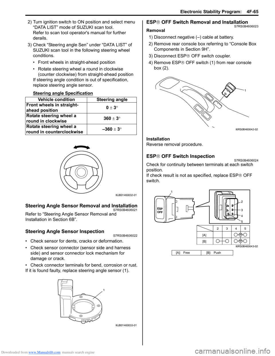
2) Turn ignition switch to ON position and select menu
“DATA LIST” mode of SUZUKI scan tool.
Refer to scan tool operator's manual for further
derails.
3) Check “Steering angle Sen” under “DATA LIST” of SUZUKI scan tool in th e following steering wheel
conditions.
• Front wheels in straight-ahead position
• Rotate steering wheel a round in clockwise (counter clockwise) from straight-ahead position
If steering angle condition is out of specification,
replace steering angle sensor.
Steering angle Specification
Steering Angle Sensor Removal and InstallationS7RS0B4606021
Refer to “Steering Angle Sensor Removal and
Installation in Section 6B”.
Steering Angle Sensor InspectionS7RS0B4606022
• Check sensor for dents, cracks or deformation.
• Check sensor connector (sensor side and harness
side) and sensor connector lock mechanism for
damage or crack.
• Check connector terminals for bend, corrosion or rust.
If it is found faulty, replace steering angle sensor (1).
ESP ® OFF Switch Removal and InstallationS7RS0B4606023
Removal
1) Disconnect negative (–) cable at battery.
2) Remove rear console box referring to “Console Box Components in Section 9H”.
3) Disconnect ESP ® OFF switch coupler.
4) Remove ESP ® OFF switch (1) from rear console
box (2).
Installation
Reverse removal procedure.
ESP ® OFF Switch InspectionS7RS0B4606024
Check for continuity between terminals at each switch
position.
If check result is not as specified, replace ESP ® OFF
switch.
Vehicle condition Steering angle
Front wheels in straight-
ahead position 0
± 3 °
Rotate steering wheel a
round in clockwise 360
± 3°
Rotate steering wheel a
round in counterclockwise –360
± 3 °
I6JB01460032-01
1
I6JB01460033-01
[A]: Free [B]: Push
1
I6RS0B460042-02
[A]
[B]2345
2
3
4
1
5
I6RS0B460043-02