2008 SUZUKI SWIFT Bearing clearance
[x] Cancel search: Bearing clearancePage 349 of 1496
Downloaded from www.Manualslib.com manuals search engine Engine Mechanical: 1D-64
Honing or Reboring Cylinders1) When any cylinder needs reboring, all other cylinders must also be rebored at the same time.
2) Select oversized piston according to amount of cylinder wear.
Oversize piston specification
Oversize 0.50: 78.453 – 78.468 mm (3.0887 –
3.0893 in.)
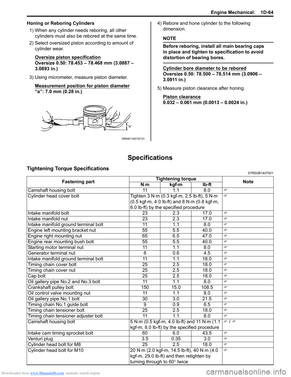
3) Using micrometer, measure piston diameter. Measurement position for piston diameter
“a”: 7.0 mm (0.28 in.) 4) Rebore and hone cylinder to the following
dimension.
NOTE
Before reboring, install all main bearing caps
in place and tighten to specification to avoid
distortion of bearing bores.
Cylinder bore diameter to be rebored
Oversize 0.50: 78.500 – 78.514 mm (3.0906 –
3.0911 in.)
5) Measure piston clearance after honing. Piston clearance
0.032 – 0.061 mm (0.0013 – 0.0024 in.)
Specifications
Tightening Torque SpecificationsS7RS0B1407001
I2RH01140157-01
Fastening part Tightening torque
Note
N ⋅mkgf-mlb-ft
Camshaft housing bolt 11 1.1 8.0 �)
Cylinder head cover bolt Tighten 3 N ⋅m (0.3 kgf-m, 2.5 lb-ft), 5 N ⋅m
(0.5 kgf-m, 4.0 lb-ft) and 8 N ⋅m (0.8 kgf-m,
6.0 lb-ft) by the specified procedure �)
Intake manifold bolt 23 2.3 17.0 �)
Intake manifold nut 23 2.3 17.0 �)
Intake manifold ground terminal bolt 11 1.1 8.0 �)
Engine left mounting bracket nut 55 5.5 40.0 �)
Engine right mounting nut 65 6.5 47.0 �)
Engine rear mounting bush bolt 55 5.5 40.0 �)
Starting motor terminal nut 11 1.1 8.0 �)
Generator terminal nut 6 0.6 4.5 �)
Intake manifold ground terminal bolt 11 1.1 18.0 �)
Timing chain cover bolt 25 2.5 18.0 �)
Timing chain cover nut 25 2.5 18.0 �)
Cap bolt 25 2.5 18.0 �)
Oil gallery pipe No.2 and No.3 bolt 11 1.1 8.0 �)
Crankshaft pulley bolt 150 15.0 108.5 �)
Oil control valve mounting nut 11 1.1 8.0 �)
Oil gallery pipe No.1 bolt 30 3.0 21.5 �)
Timing chain No.1 guide bolt 9 0.9 6.5 �)
Timing chain tensioner bolt 25 2.5 18.0 �)
Timing chain tensioner adjuster bolt 11 1.1 8.0 �)
Camshaft housing bolt 5 N ⋅m (0.5 kgf-m, 4.0 lb-ft) and 11 N ⋅m (1.1
kgf-m, 8.0 lb-ft) by the specified procedure �)
/ �)
Intake cam timing sprocket bolt 60 6.0 43.5 �)
Venturi plug 3.5 0.35 3.0 �)
Cylinder head bolt for M8 25 2.5 18.0 �)
Cylinder head bolt for M10 20 N ⋅m (2.0 kgf-m, 14.5 lb-ft), 40 N ⋅m (4.0
kgf-m, 29.0 lb-ft) and then retighten by
turning through to 60 ° twice �)
Page 469 of 1496

Downloaded from www.Manualslib.com manuals search engine Wheels and Tires: 2D-2
Lower than recommended pressure can cause:
• Tire squeal on turns
• Hard Steering
• Rapid and uneven wear on the edges of the tread
• Tire rim bruises and rupture
• Tire cord breakage
• High tire temperature
• Reduced handling
• High fuel consumption
Replacement Tires
When replacement is necessary, the original equipment
type tire should be used. Refer to the Tire Placard.
Replacement tires should be of the same size, load
range and construction as those originally on the vehicle.
Use of any other size or type tire may affect ride,
handling, speedometer / odometer calibration, vehicle
ground clearance and tire or snow chain clearance to the
body and chassis.
It is recommended that new tires be installed in pairs on
the same axle. If necessary to replace only one tire, it
should be paired with the tire having the most tread, to
equalize braking traction.
WARNING!
Do not mix different types of tires on the
same vehicle such as radial, bias and bias-
belted tires except in emergencies, because
handling may be seriously affected and may
result in loss of control.
The metric term for tire infl ation pressure is the kilo
pascal (kPa). Tire pressures is usually printed in both
kPa and kgf/cm
2 on the “Tire Placard”.
Metric tire gauges are available from tool suppliers.
The chart, shown the table, converts commonly used
inflation pressures from kPa to kgf/cm
2 and psi.
Wheels DescriptionS7RS0B2401002
Wheel Maintenance
Wheel repairs that use welding, heating, or peening are
not approved. All damaged wheels should be replaced.
Replacement Wheels
Wheels must be replaced if they are bent, dented, have
excessive lateral or radial runout, air leak through welds,
have elongated bolt holes, if lug wheel bolts won’t stay
tight, or if they are heavily rusted. Wheels with greater
runout than shown in the following may cause
objectional vibrations.
Replacement wheels must be equivalent to the original
equipment wheels in load capacity, diameter, rim with
offset and mounting configuration. A wheel of improper
size or type may affect wheel and bearing life, brake
cooling, speedometer / odometer calibration, vehicle
ground clearance and tire clearance to body and
chassis.
How to Measure Wheel Runout
To measure the wheel runout, it is necessary to use an
accurate dial indicator. The tire may be on or off the
wheel. The wheel should be installed to the wheel
balancer of the like for proper measurement.
Take measurements of both lateral runout “a” and radial
runout “b” at both inside an d outside of the rim flange.
With the dial indicator set in place securely, turn the
wheel one full revolution slowly and record every reading
of the indicator.
When the measured runout exceeds the specification
and correction by the balancer adjustment is impossible,
replace the wheel. If the reading is affected by welding,
paint or scratch, it should be ignored.
Lateral runout limit “a”
: 0.3 mm (0.012 in.)
Radial runout limit “b”
: 0.3 mm (0.012 in.)
kPa kgf/cm2psi
Conversion: 1 psi =
6.895 kPa 1 kgf/cm
2 =
98.066 kPa 160 1.6 23
180 1.8 26
200 2.0 29
220 2.2 32
240 2.4 35
260 2.6 38
280 2.8 41
300 3.0 44
I4RS0A240001-01
Page 558 of 1496
Downloaded from www.Manualslib.com manuals search engine 4E-19 ABS:
DTC TroubleshootingStep Action Yes No 1 Was “ABS Check” performed? Go to Step 2. Go to “ABS Check”.
2 1) Disconnect applicable ABS wheel speed sensor coupler with ignition switch OFF.
2) Measure resistance betw een terminals of ABS wheel
speed sensor. Refer to “Front Wheel Speed Sensor
Inspection” and/or “Front Wheel Encoder On-Vehicle
Inspection”.
Is measured resistance value as specified? Go to Step 3. Replace ABS wheel
speed sensor assembly.
3 1) Turn ignition switch OFF. 2) Connect applicable ABS wh eel speed sensor coupler.
3) Disconnect ABS hydraulic unit / control module connector.
4) Check for proper connection to ABS control module at each sensor terminal.
5) If OK, then turn ignition switch ON and measure voltage between applicable sensor terminal of module connector
and body ground.
Is it 0 V? Go to Step 4. ABS wheel speed
sensor circuit shorted to
power.
4 1) Turn ignition switch OFF. 2) Measure resistance between the following points.• Both ABS hydraulic unit / control module connector terminals of the correspo nding sensor. This check
result should be the same as Step 2).
• Either terminal of wheel speed sensor coupler and body ground. This check result should be no
continuity.
Are both check results OK? Go to Step 5. Circuit open or shorted
to ground.
5 1) Remove applicable ABS wheel speed sensor. 2) Check sensor for damage or foreign material attached.
Is it in good condition? Go to Step 6. Clean, repair or replace.
6 Check front and/or rear sensor ring for the following (remove rear drum as necessary):
• Sensor ring serration (teeth) neither missing nor damaged
• No foreign material being attached
• Sensor ring not being eccentric
• Wheel bearing free from excessive play
Are they in good condition? Go to Step 7. Clean, repair or replace.
7 1) Install ABS wheel speed sensor to knuckle. 2) Tighten sensor bolt to specified torque and check that there is no clearance between sensor and knuckle.
Is it OK? Go to Step 8. Replace ABS wheel
speed sensor.
8 Refer to “Front / Rear Wheel Speed Sensor On-Vehicle Inspection” and/or “Rear Wheel Speed Sensor Removal and
Installation”, check output voltage or waveform.
Is specified voltage and/or waveform obtained? Substitute a known-
good ABS hydraulic unit
/ control module
assembly and recheck.
Replace sensor and
recheck.
Page 607 of 1496
Downloaded from www.Manualslib.com manuals search engine Electronic Stability Program: 4F-33
2Check wheel speed sensor circuit
1) Turn ignition switch OFF.
2) Disconnect connector from ESP ® control module and
applicable wheel speed sensor coupler.
3) Check for proper connection of ESP ® control module
and wheel speed sensor coupler.
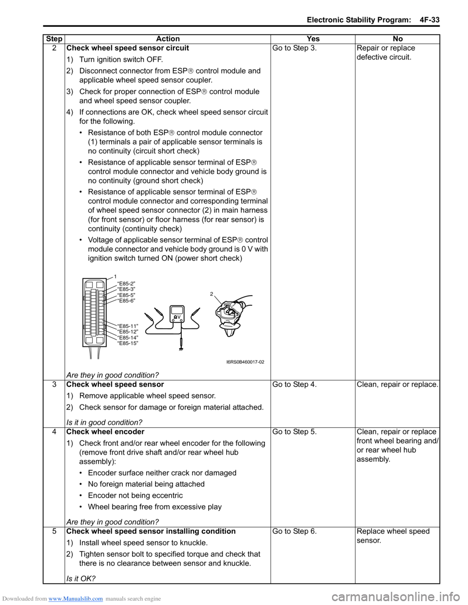
4) If connections are OK, che ck wheel speed sensor circuit
for the following.
• Resistance of both ESP ® control module connector
(1) terminals a pair of app licable sensor terminals is
no continuity (circuit short check)
• Resistance of applicable sensor terminal of ESP ®
control module connector and vehicle body ground is
no continuity (ground short check)
• Resistance of applicable sensor terminal of ESP ®
control module connector and corresponding terminal
of wheel speed sensor connector (2) in main harness
(for front sensor) or floor harness (for rear sensor) is
continuity (continuity check)
• Voltage of applicable sensor terminal of ESP ® control
module connector and vehicle body ground is 0 V with
ignition switch turned ON (power short check)
Are they in good condition? Go to Step 3. Repair or replace
defective circuit.
3 Check wheel speed sensor
1) Remove applicable wheel speed sensor.
2) Check sensor for damage or foreign material attached.
Is it in good condition? Go to Step 4. Clean, repair or replace.
4 Check wheel encoder
1) Check front and/or rear wheel encoder for the following
(remove front drive shaft and/or rear wheel hub
assembly):
• Encoder surface neither crack nor damaged
• No foreign material being attached
• Encoder not being eccentric
• Wheel bearing free from excessive play
Are they in good condition? Go to Step 5. Clean, repair or replace
front wheel bearing and/
or rear wheel hub
assembly.
5 Check wheel speed sensor installing condition
1) Install wheel speed sensor to knuckle.
2) Tighten sensor bolt to specified torque and check that
there is no clearance between sensor and knuckle.
Is it OK? Go to Step 6. Replace wheel speed
sensor.
Step Action Yes No
1
2“E85-2”“E85-3”“E85-5”
“E85-6”
“E85-11”
“E85-12”
“E85-14”
“E85-15”
I6RS0B460017-02
Page 834 of 1496
Downloaded from www.Manualslib.com manuals search engine 5B-20 Manual Transmission/Transaxle:
9) Install side bearing retainer as follows.a) Install differential side bearing outer race to left case and then tap and accustom outer race
using special tool and plastic hammer.
CAUTION!
Do not drive in a race with hammer.
Driving it may cause to damage bearing.
Special tool
(A): 09926–27610
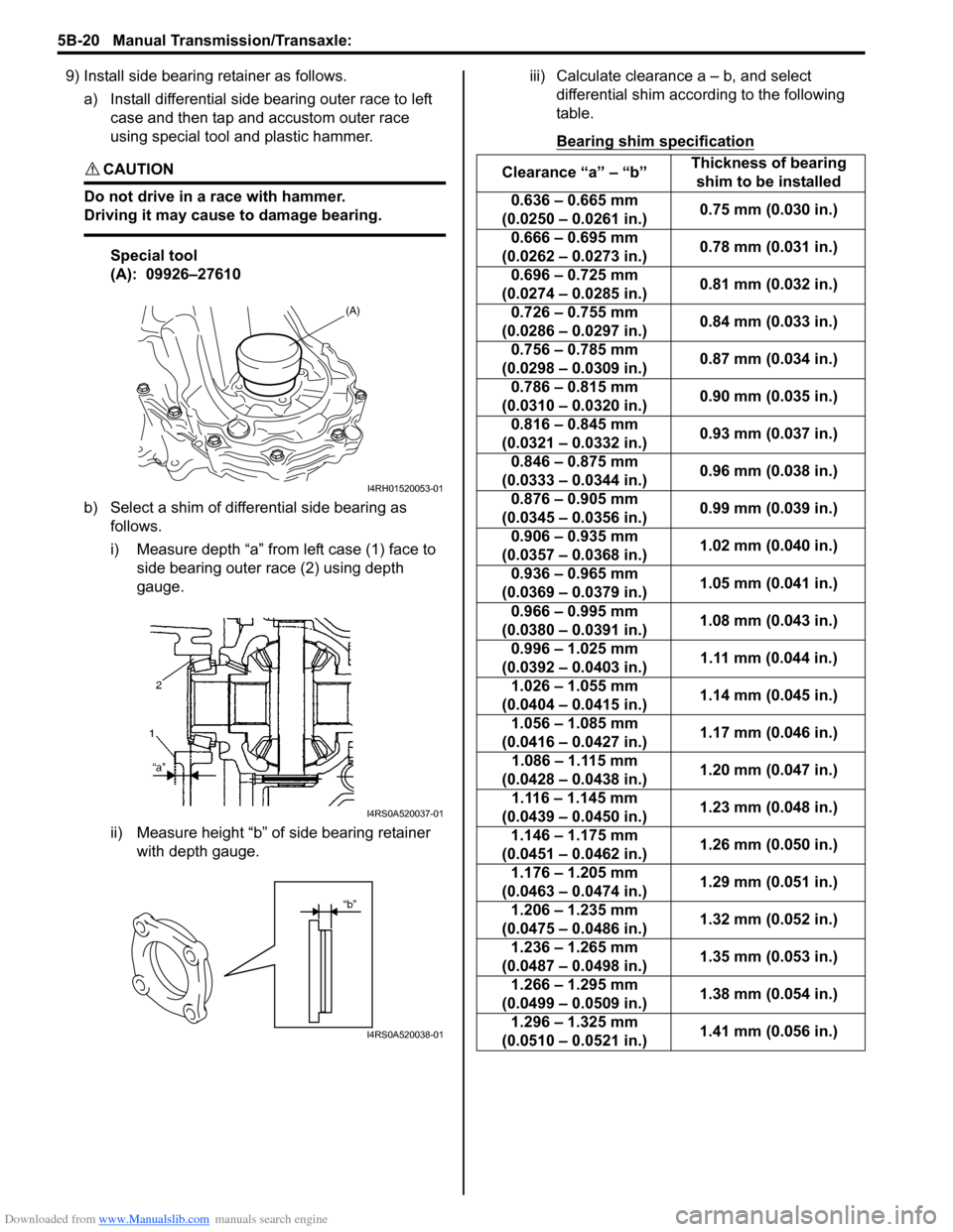
b) Select a shim of differential side bearing as follows.
i) Measure depth “a” from left case (1) face to side bearing outer race (2) using depth
gauge.
ii) Measure height “b” of side bearing retainer with depth gauge. iii) Calculate clearance a – b, and select
differential shim acco rding to the following
table.
Bearing shim specification
(A)
I4RH01520053-01
I4RS0A520037-01
“b”
I4RS0A520038-01
Clearance “a” – “b” Thickness of bearing
shim to be installed
0.636 – 0.665 mm
(0.0250 – 0.0261 in.) 0.75 mm (0.030 in.)
0.666 – 0.695 mm
(0.0262 – 0.0273 in.) 0.78 mm (0.031 in.)
0.696 – 0.725 mm
(0.0274 – 0.0285 in.) 0.81 mm (0.032 in.)
0.726 – 0.755 mm
(0.0286 – 0.0297 in.) 0.84 mm (0.033 in.)
0.756 – 0.785 mm
(0.0298 – 0.0309 in.) 0.87 mm (0.034 in.)
0.786 – 0.815 mm
(0.0310 – 0.0320 in.) 0.90 mm (0.035 in.)
0.816 – 0.845 mm
(0.0321 – 0.0332 in.) 0.93 mm (0.037 in.)
0.846 – 0.875 mm
(0.0333 – 0.0344 in.) 0.96 mm (0.038 in.)
0.876 – 0.905 mm
(0.0345 – 0.0356 in.) 0.99 mm (0.039 in.)
0.906 – 0.935 mm
(0.0357 – 0.0368 in.) 1.02 mm (0.040 in.)
0.936 – 0.965 mm
(0.0369 – 0.0379 in.) 1.05 mm (0.041 in.)
0.966 – 0.995 mm
(0.0380 – 0.0391 in.) 1.08 mm (0.043 in.)
0.996 – 1.025 mm
(0.0392 – 0.0403 in.) 1.11 mm (0.044 in.)
1.026 – 1.055 mm
(0.0404 – 0.0415 in.) 1.14 mm (0.045 in.)
1.056 – 1.085 mm
(0.0416 – 0.0427 in.) 1.17 mm (0.046 in.)
1.086 – 1.115 mm
(0.0428 – 0.0438 in.) 1.20 mm (0.047 in.)
1.116 – 1.145 mm
(0.0439 – 0.0450 in.) 1.23 mm (0.048 in.)
1.146 – 1.175 mm
(0.0451 – 0.0462 in.) 1.26 mm (0.050 in.)
1.176 – 1.205 mm
(0.0463 – 0.0474 in.) 1.29 mm (0.051 in.)
1.206 – 1.235 mm
(0.0475 – 0.0486 in.) 1.32 mm (0.052 in.)
1.236 – 1.265 mm
(0.0487 – 0.0498 in.) 1.35 mm (0.053 in.)
1.266 – 1.295 mm
(0.0499 – 0.0509 in.) 1.38 mm (0.054 in.)
1.296 – 1.325 mm
(0.0510 – 0.0521 in.) 1.41 mm (0.056 in.)
Page 836 of 1496

Downloaded from www.Manualslib.com manuals search engine 5B-22 Manual Transmission/Transaxle:
14) With putting a shim (2) on bearing outer race (3), place straightedge (1) over it and compress it by
hand through straightedge, and then measure
clearance “a” between case surface (4) and
straightedge using feeler gauge (5).
Clearance between case surface and
straightedge (Shim protrusion)
“a”: 0.08 – 0.12 mm (0.0032 – 0.0047 in.)
15) By repeating Step 14), select a suitable shim which adjusts clearance “a” to specification and put it on
bearing outer race.
NOTE
Insert 0.10 mm (0.0039 in.) feeler to know
whether or not a shim fulfills specification
quickly.
Available shim thickness
16) Place left case plate (2) inserting its end in groove of shift guide shaft (4) and tighten bolts (1) to which
thread lock cement has been applied.
NOTE
After tightening bolts, make sure that
countershaft (5) can be rotated by hand
feeling certain load.
“A”: Thread lock cement 99000–32110 (Thread
Lock Cement Super 1322)
Tightening torque
Left case plate bolt (a): 23 N·m (2.3 kgf-m, 17.0
lb-ft)
17) Install fifth gear referring to “Fifth Gear Disassembly and Assembly”.
18) Install gear shift and select shaft assembly referring to “Gear Shift and Select Shaft Assembly Removal
and Installation”.
19) Install back up light switch referring to “Back Up Light
Switch Removal and Installation”.
20) Check input shaft for rotation in each gear position.
21) Also confirm continuity of back up light switch in
reverse position using ohmmeter.
0.55 mm (0.021 in.) 0.90 mm (0.035 in.)
0.60 mm (0.023 in.) 0.95 mm (0.037 in.)
0.65 mm (0.025 in.) 1.00 mm (0.039 in.)
0.70 mm (0.027 in.) 1.05 mm (0.041 in.)
0.75 mm (0.029 in.) 1.10 mm (0.043 in.)
0.80 mm (0.031 in.) 1.15 mm (0.059 in.)
0.85 mm (0.033 in.)
I3RM0A520031-01
3. Input shaft
I4RS0A520042-01
Page 957 of 1496
Downloaded from www.Manualslib.com manuals search engine Air Conditioning System: Manual Type 7B-9
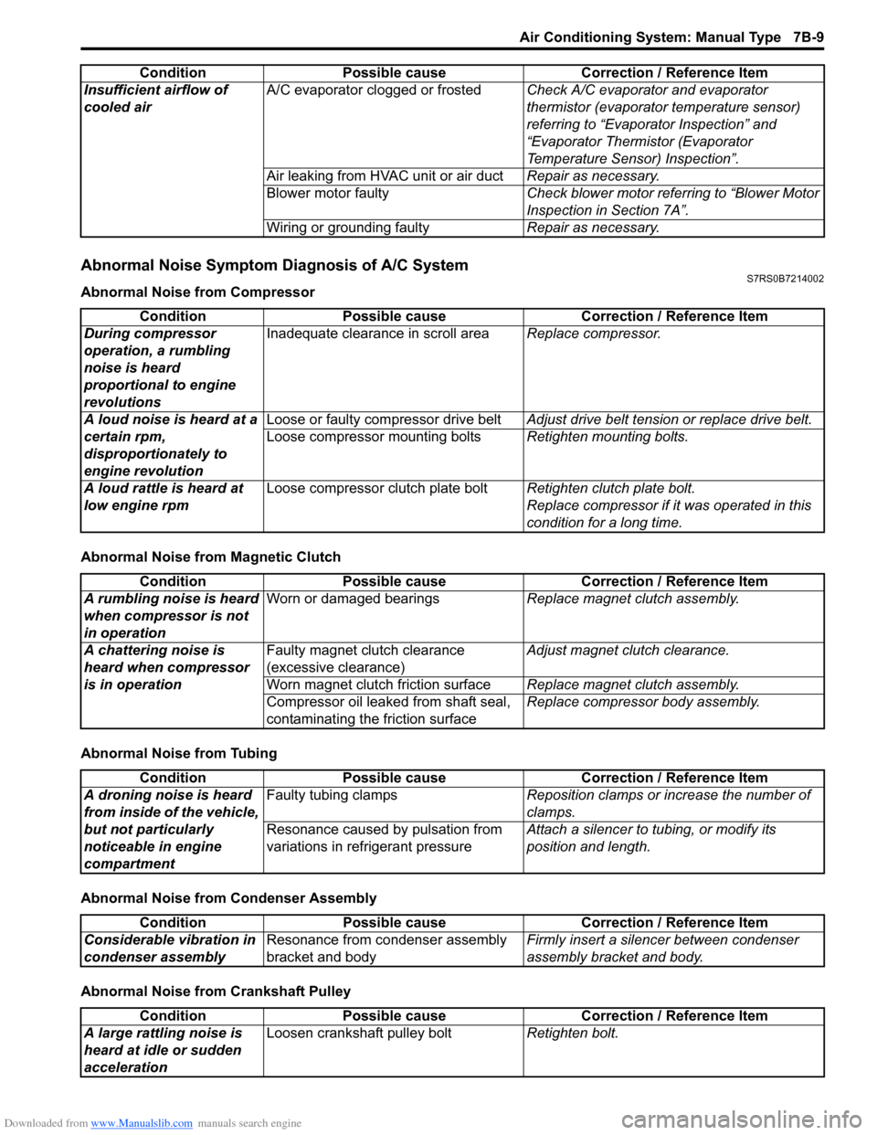
Abnormal Noise Symptom Diagnosis of A/C SystemS7RS0B7214002
Abnormal Noise from Compressor
Abnormal Noise from Magnetic Clutch
Abnormal Noise from Tubing
Abnormal Noise from Condenser Assembly
Abnormal Noise from Crankshaft PulleyInsufficient airflow of
cooled air
A/C evaporator clogged or frosted
Check A/C evaporator and evaporator
thermistor (evaporator temperature sensor)
referring to “Evaporator Inspection” and
“Evaporator Thermistor (Evaporator
Temperature Sensor) Inspection”.
Air leaking from HVAC unit or air duct Repair as necessary.
Blower motor faulty Check blower motor referring to “Blower Motor
Inspection in Section 7A”.
Wiring or grounding faulty Repair as necessary.
Condition Possible cause Correction / Reference Item
Condition
Possible cause Correction / Reference Item
During compressor
operation, a rumbling
noise is heard
proportional to engine
revolutions Inadequate clearance in scroll area
Replace compressor.
A loud noise is heard at a
certain rpm,
disproportionately to
engine revolution Loose or faulty compressor drive belt
Adjust drive belt tension or replace drive belt.
Loose compressor mounting bolts Retighten mounting bolts.
A loud rattle is heard at
low engine rpm Loose compressor clutch plate bolt
Retighten clutch plate bolt.
Replace compressor if it was operated in this
condition for a long time.
Condition Possible cause Correction / Reference Item
A rumbling noise is heard
when compressor is not
in operation Worn or damaged bearings
Replace magnet clutch assembly.
A chattering noise is
heard when compressor
is in operation Faulty magnet clutch clearance
(excessive clearance)
Adjust magnet clutch clearance.
Worn magnet clutch friction surface Replace magnet clutch assembly.
Compressor oil leaked from shaft seal,
contaminating the friction surface Replace compressor body assembly.
Condition
Possible cause Correction / Reference Item
A droning noise is heard
from inside of the vehicle,
but not particularly
noticeable in engine
compartment Faulty tubing clamps
Reposition clamps or increase the number of
clamps.
Resonance caused by pulsation from
variations in re frigerant pressure Attach a silencer to tubing, or modify its
position and length.
Condition
Possible cause Correction / Reference Item
Considerable vibration in
condenser assembly Resonance from condenser assembly
bracket and body Firmly insert a silenc
er between condenser
assembly bracket and body.
Condition Possible cause Correction / Reference Item
A large rattling noise is
heard at idle or sudden
acceleration Loosen crankshaft pulley bolt
Retighten bolt.