Page 359 of 1496

Downloaded from www.Manualslib.com manuals search engine Engine Lubrication System: 1E-7
6) After fitting oil pan to cylinder block, run in securing bolts and start tightening at the center: move wrench
outward, tightening one bolt at a time. Tighten bolts
and nuts to specified torque.
Tightening torque
Oil pan bolt (M6) (a): 11 N·m (1.1 kgf-m, 8.0 lb-ft)
Oil pan bolt (M10) (c): 55 N·m (5.5 kgf-m, 40.0 lb-
ft)
Oil pan nut (e): 11 N·m (1.1 kgf-m, 8.0 lb-ft)
7) Install new gasket and drain plug to oil pan. Tighten drain plug to specified torque.
Tightening torque
Oil pan drain plug (b): 35 N·m (3.5 kgf-m, 25.5 lb-
ft)
8) Tighten transaxle stiffener bolts to specified torque. Tightening torque
Transaxle stiffener bolt (d): 55 N·m (5.5 kgf-m,
40.0 lb-ft)
9) Install exhaust manifold stiffener (2) and exhaust No.1 pipe (1) and heated oxygen sensor No.2
(connector color: green) (3) referring to “Exhaust
System Components in Section 1K”. 10) Install clutch housing lower plate (1).
11) Install oil level gauge.
12) Refill engine with engine oil referring to “Engine Oil
and Filter Change in Section 0B”.
13) Verify that there is no en gine oil leakage and exhaust
gas leakage at each connection.
Oil Pan and Oil Pump Strainer CleaningS7RS0B1506006
• Clean sealing surface between oil pan and cylinder block.
Remove oil, old sealant, and dust from sealing
surface.
• Clean oil pump strainer screen (1).(a)
(b)
(c)(e)
(d)I4RS0A150008-01
2
1
3
I4RS0A150003-01
1I4RS0A150004-01
I2RH0B150016-01
Page 360 of 1496
Downloaded from www.Manualslib.com manuals search engine 1E-8 Engine Lubrication System:
Oil Pump ComponentsS7RS0B1506007
Oil Pump Removal and InstallationS7RS0B1506008
Oil pump is incorporated with timing chain cover.
For removal and installation, refer to “Timing Chain
Cover Removal and Installation in Section 1D”.
Oil Pump Disassembly and ReassemblyS7RS0B1506009
Disassembly1) Remove rotor plate (1) by removing its mounting bolts. 2) Remove outer rotor (1) and inner rotor (2).
3) Remove relief valve (1), spring (2) and retainer (3) by
removing circlip (4).
I4RS0A150010-01
1. Rotor plate 6. Rotor plate bolt10. Circlip
2. O-ring 7. Relief valve : 11 N⋅m (1.1 kgf-mm 8.0 lb-ft)
3. Outer rotor 8. Spring : Do not reuse.
4. Inner rotor 9. Retainer : Apply thin coat of engine oil to sliding surface.
5. Timing chain cover 10. Circlip
I2RH0B150018-01
I2RH0B150019-01
I2RH0B150020-01
Page 361 of 1496

Downloaded from www.Manualslib.com manuals search engine Engine Lubrication System: 1E-9
Reassembly1) Wash, clean and then dry all disassembled parts.
2) Apply thin coat of engine oil to inner and outer rotors, oil seal lip portion, inside surfaces of oil pump case
and plate.
3) Install outer (1) and inner rotors (2) to oil pump case.
4) Apply engine oil to relief valve (1) and spring (2), and install them with retainer (3) and new circlip (4) to
rotor plate (5).
5) Install rotor plate and tighten all bolts to specified torque. After installing plate, check to be sure that
rotors turn smoothly by hand (0.3 N ⋅m (0.03 kgf-m,
0.25 lb-ft) torque or below).
Tightening torque
Oil pump rotor plate bolt (a): 11 N·m (1.1 kgf-m,
8.0 lb-ft)Oil Pump InspectionS7RS0B1506010
Oil Seal
Check oil seal lip for fault or other damage. Replace as
necessary.
Oil Pump
• Check outer (1) and inner rotors (2), rotor plate, and oil pump case for excessive wear or damage.
• Check relief valve (1) for excessive wear or damage
and operates smoothly.
I2RH0B150019-01
I3RM0A150005-01
I2RH0B150022-01
I2RH0B150023-01
I2RH0B150019-01
I2RH0B150025-01
Page 362 of 1496

Downloaded from www.Manualslib.com manuals search engine 1E-10 Engine Lubrication System:
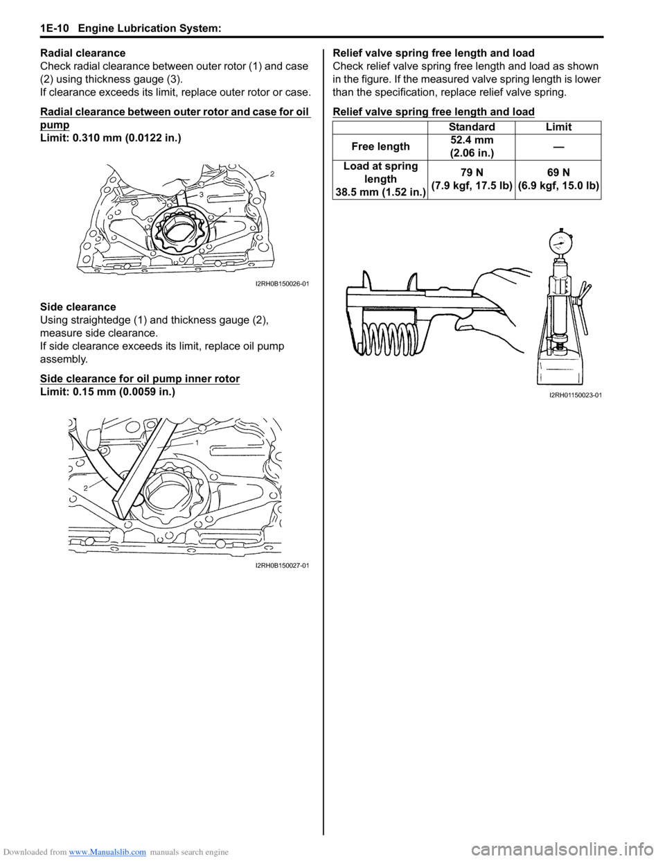
Radial clearance
Check radial clearance between outer rotor (1) and case
(2) using thickness gauge (3).
If clearance exceeds its limit, replace outer rotor or case.
Radial clearance between outer rotor and case for oil
pump
Limit: 0.310 mm (0.0122 in.)
Side clearance
Using straightedge (1) and thickness gauge (2),
measure side clearance.
If side clearance exceeds its limit, replace oil pump
assembly.
Side clearance for oil pump inner rotor
Limit: 0.15 mm (0.0059 in.)Relief valve spring free length and load
Check relief valve spring free length and load as shown
in the figure. If the measured valve spring length is lower
than the specification, replace relief valve spring.
Relief valve spring free length and load
I2RH0B150026-01
I2RH0B150027-01
Standard Limit
Free length 52.4 mm
(2.06 in.) —
Load at spring length
38.5 mm (1.52 in.) 79 N
(7.9 kgf, 17.5 lb) 69 N
(6.9 kgf, 15.0 lb)
I2RH01150023-01
Page 363 of 1496

Downloaded from www.Manualslib.com manuals search engine Engine Lubrication System: 1E-11
Specifications
Tightening Torque SpecificationsS7RS0B1507001
NOTE
The specified tightening torque is also described in the following.
“Heat Exchanger Components”
“Oil Pan and Oil Pump Strainer Components”
“Oil Pump Components”
Reference:
For the tightening torque of fastener not specified in this section, refer to “Fasteners Information in Section 0A”.
Special Tools and Equipment
Recommended Service MaterialS7RS0B1508001
NOTE
Required service material is also described in the following.
“Heat Exchanger Components”
“Oil Pan and Oil Pump Strainer Components”
“Oil Pump Components”
Special ToolS7RS0B1508002
Fastening part Tightening torque
Note
N ⋅mkgf-mlb-ft
Oil pressure switch 13 1.3 9.5 �)
Heat exchanger stand bolt 22 2.2 16.0 �)
Oil pump strainer bolt 11 1.1 8.0 �)
Oil pump strainer bracket bolt 11 1.1 8.0 �)
Oil pan bolt (M6) 11 1.1 8.0 �)
Oil pan bolt (M10) 55 5.5 40.0 �)
Oil pan nut 11 1.1 8.0 �)
Oil pan drain plug 35 3.5 25.5 �)
Transaxle stiffener bolt 55 5.5 40.0 �)
Oil pump rotor plate bolt 11 1.1 8.0 �)
MaterialSUZUKI recommended product or Specification Note
Sealant SUZUKI Bond No.1217G P/No.: 99000–31260�)
09915–77310 09915–78211
Oil pressure gauge (0-10kg/
cm2) Oil pressure gauge
attachment
�)�)